LumenRadio CRMXTIMO101 2.4G Wireless Control Module User Manual 1502 ver20
LumenRadio AB 2.4G Wireless Control Module 1502 ver20
UserManual.wiki
>
LumenRadio
>
CRMXTIMO101 User Manual
>
User manual part 2
Contents
1.
User manual part 1
2.
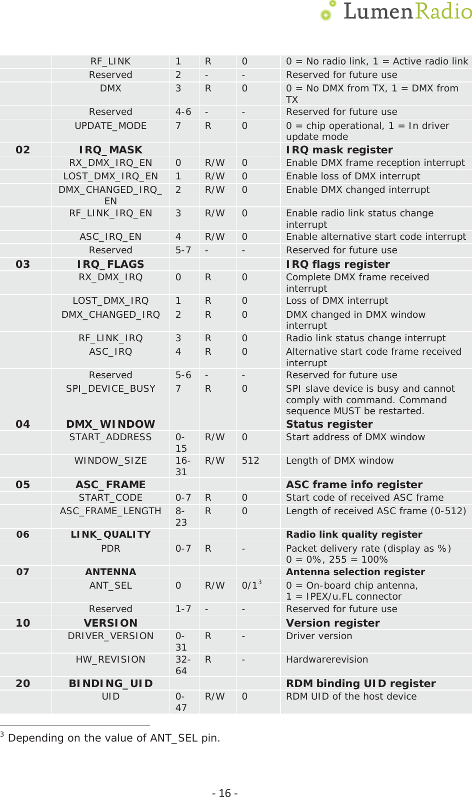
User manual part 2
User manual part 2
Navigation menu
Upload a User Manual
Namespaces
Wiki Guide
HTML
PDF
Info
Views
User Manual
Discussion / Help
Navigation