LumenRadio CRMXTIMO101 2.4G Wireless Control Module User Manual 1502 ver20
LumenRadio AB 2.4G Wireless Control Module 1502 ver20
Contents
- 1. User manual part 1
- 2. User manual part 2
User manual part 2
Ͳ16Ͳ
RF_LINK 1 R 0 0 = No radio link, 1 = Active radio link
Reserved 2 - - Reserved for future use
DMX 3 R 0 0 = No DMX from TX, 1 = DMX from
TX
Reserved 4-6
- - Reserved for future use
UPDATE_MODE 7 R 0 0 = chip operational, 1 = In driver
update mode
02 IRQ_MASK IRQ mask register
RX_DMX_IRQ_EN 0 R/W 0 Enable DMX frame reception interrupt
LOST_DMX_IRQ_EN 1 R/W 0 Enable loss of DMX interrupt
DMX_CHANGED_IRQ_
EN 2 R/W 0 Enable DMX changed interrupt
RF_LINK_IRQ_EN 3 R/W 0 Enable radio link status change
interrupt
ASC_IRQ_EN 4 R/W 0 Enable alternative start code interrupt
Reserved 5-7
- - Reserved for future use
03 IRQ_FLAGS IRQ flags register
RX_DMX_IRQ 0 R 0 Complete DMX frame received
interrupt
LOST_DMX_IRQ 1 R 0 Loss of DMX interrupt
DMX_CHANGED_IRQ 2 R 0 DMX changed in DMX window
interrupt
RF_LINK_IRQ 3 R 0 Radio link status change interrupt
ASC_IRQ 4 R 0 Alternative start code frame received
interrupt
Reserved 5-6
- - Reserved for future use
SPI_DEVICE_BUSY 7 R 0 SPI slave device is busy and cannot
comply with command. Command
sequence MUST be restarted.
04 DMX_WINDOW Status register
START_ADDRESS 0-
15 R/W 0 Start address of DMX window
WINDOW_SIZE 16-
31 R/W 512 Length of DMX window
05 ASC_FRAME ASC frame info register
START_CODE 0-7
R 0 Start code of received ASC frame
ASC_FRAME_LENGTH 8-
23 R 0 Length of received ASC frame (0-512)
06 LINK_QUALITY Radio link quality register
PDR 0-7
R - Packet delivery rate (display as %)
0 = 0%, 255 = 100%
07 ANTENNA Antenna selection register
ANT_SEL 0 R/W 0/13 0 = On-board chip antenna,
1 = IPEX/u.FL connector
Reserved 1-7
- - Reserved for future use
10 VERSION Version register
DRIVER_VERSION 0-
31 R - Driver version
HW_REVISION 32-
64 R - Hardwarerevision
20 BINDING_UID RDM binding UID register
UID 0-
47 R/W 0 RDM UID of the host device
3 Depending on the value of ANT_SEL pin.

Ͳ17Ͳ
Interrupts
The IRQ pin is used to indicate that there is one (or more) pending interrupt that have
been enabled through the IRQ_MASK register. The IRQ pin is also used to indicate that
the SPI slave is ready to receive the second transaction of an ongoing SPI command
sequence.
The IRQ pin will always go high (inactive) after a successful SPI transaction. If any
interrupts are pending, or when the chip is ready for the second transaction in a SPI
command sequence it will be indicated through a high-to-low transition on the IRQ pin.
RX_DMX_IRQ
Asserted when a complete DMX frame has been received. Cleared by issuing a
READ_DMX command sequence.
LOST_DMX_IRQ
Asserted when DMX stream is lost. This may be an effect of losing radio link, or if DMX
stream in to the transmitter is terminated (for instance the DMX cable to the transmitter
is unplugged). Cleared by reading the STATUS register.
DMX_CHANGED_IRQ
Asserted when a complete DMX frame has been received and any slot within the DMX
window has changed value. Cleared by issuing a READ_DMX command sequence.
RF_LINK_IRQ
Asserted whenever the state of the radio link has changed. This may be:
xradio link is lost
xradio link is established
xreceiver got paired to transmitter
xreceiver got unpaired from transmitter
Cleared by reading the STATUS register.
ASC_IRQ
Asserted when a complete ASC frame has been received. Cleared by reading the
ASC_FRAME register.
DMX Window register
The DMX_WINDOW register is used for setting up the DMX window filtering function.
Please refer to the section about DMX window on page 19 for more details.
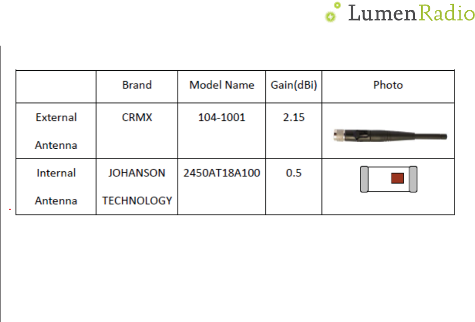
Antenna selection
This register allows for controlling if the on-board chip antenna or an external antenna
connected to the IPEX/u.FL connector is being used. This register overrides the selection
made via the ANT_SEL pin. ANT_SEL pin is internally pulled high to default to IPEX/u.FL
connector.
Ͳ18Ͳ
Version register
This section describes the data that can be read from the VERSION register.
Hardware revision
Hardware revision is a 32bit number that shall be translated into a string. It indicates
the revision number of the TiMo module. For instance the 32 bit value in hexadecimal
form 0x000A0001 corresponds to module revision “000A0001”.
Driver version
The driver version is a 32bit value that shall be translated into a string on the form
X.Y.Z.Y where X is the most significant byte of the 32 bit version number and Y is the
least significant byte. For instance the 32 bit value 0x01000103 shall be presented as
1.0.1.3 on any UI or in any written representation.
Binding UID
The binding UID register can be written by the host processor to match the fixture’s RDM
UID. This will result in SuperNova combing the devices together in the UI representation,
resulting in a better user experience with a more user-friendly interface.
Ͳ19Ͳ
DMX Interface
SPI
DMX data is available to be read over SPI. This applies to both Null Start Code (NSC)
data and Alternate Start Code (ASC) data.
DMX window
The DMX window feature allows a host CPU to set up a span of DMX slots (aka. a DMX
window) that the host is interested of. This will reduce the load of the host since it does
not need to buffer and parse the entire DMX frame.
Instead the host can get an interrupt request (DMX_CHANGED_IRQ) from TiMo RX RDM
whenever data has changed inside the DMX window.
RX_DMX_IRQ is not affected by the settings of the DMX window.
Reading DMX data over SPI
When reading DMX data over SPI, the longest block of data possible to read is 128 bytes.
If it is required to read more than 128 bytes this must be done by performing multiple
consecutive READ_DMX command sequences.
The internal data block counter is reset when the end of the DMX window is reached, or
if any other command is being sent to the SPI slave.
Please note that RDM start code messages are not currently supported over the SPI
interface, so RDM communications shall be carried out over the UART DMX/RDM
interface (pins 8, 10, 11 and 12).
UART DMX/RDM interface
The UART DMX/RDM interface of the TiMo RX RDM consist of 4 digital signals that can be
used to interface an RS485 driver IC compliant with the ANSI E1.11 DMX512-A standard
to facilitate a DMX512-A compatible interface. Please refer to the example schematic for
details on how to connect an RS485 driver IC.
The DMX interface can also be used for CMOS/TTL level directly interfacing for instance a
host CPU.
NOTE: Signal on RXD pin must NOTexceedVDD! If 5V signal is used, a level shifting
circuit must be used. Please see example schematics on page 7for details on how to use
a 5V IC.
DMX and RDM termination and line bias
DMX and RDM termination and line bias circuitry is not provided as part of TiMo (since
the data is provided at TTL level). This circuit is left to the device manufacturer to
provide as required for each particular application and device.
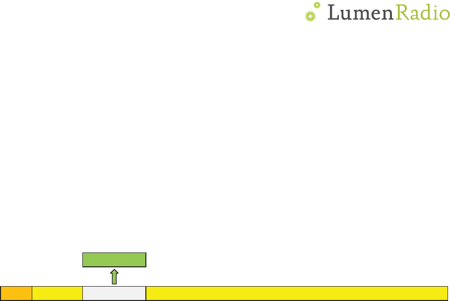
DMX512 data (512ch)
SC
Relevant data

Ͳ20Ͳ
Termination and line bias circuitry requirements shall follow ”ANSI E1.20 - 2006 /
Entertainment Technology-RDM-Remote Device Management over USITT DMX512
Networks”or later revisions.
IMPORTANT: Biasing is mandatory for all RDM implementations.
DMX frame rate and size
TiMo RX RDM will auto sense the DMX frame rate and frame size and accept all
variations that are within the USITT DMX-512 (1986 & 1990) and DMX-512-A standards.
Minimum DMX frame size is 1 slot and maximum is 512 slots.
Minimum DMX frame rate for normal operation is 0.8 frames per second and maximum
is 830 frames per second.
Input frame rates below 0.8 frames per second, i.e. more than 1.25s has elapsed since
the last frame, will be treated as a loss of DMX and the RS485 driverIC will be set in a
high-impedance/tri-state mode until another DMX frame is detected.
CRMX will propagate DMX through the system maintaining the input frame rate and
frame size with the exception of frame rates that exceed those allowed by the DMX 512-
A standard.
Input DMX frame rates above 830 frames per second will propagate through the system
at 830 frames per second to ensure that the DMX output is compliant with the DMX512-
A standard.
DMX start codes
DMX packets with start codes other than the DMX default 0x00 (also known as the Null
Start Code, or NSC) and the RDM start code (0xCC) will be propagated through the
system, and are subject to the same rules and limitations as the null start code packets.
Such frames are called Alternate Start Code, or ASC, frames.
RDM start code frames
Frames with RDM start code (0xCC) arehandled separately by transmitters in CRMX
systems, as part of the proxy functionality. Transmitters manage the interleaving of RDM
frames with null start code packets across the air, and may interleave other RDM frames
that are needed to manage the proxy functionality. This may result in RDM frames can
appear on the DMX/RDM interface in a different order than on the input of the
transmitter.
All RDM frames are handling in compliance with the PLASA E1.20 standard.
Alternate start code frames
ASC (Alternate Start Code) frames can be read separately from the SPI interface or the
DMX/RDM interface. Over SPI, the ASC_FRAME register contains basic information about
the last received ASC frame. The information available in this register is start code and
length (number of slots).

Ͳ21Ͳ
Reading ASC data over SPI
When reading ASC data over SPI, the longest block of data possible to read is 128 bytes.
If it is required to read more than 128 bytes this must be done by performing multiple
consecutive READ_ASC command sequences.
The internal data block counter is reset when the end of the ASC frame is reached, or if
any other command is being sent to the SPI slave.

Ͳ22Ͳ
Output Power
The radio output power of the TiMo module can not be directly controlled. Instead the
radio output power is automatically adjusted to match the output power from the
transmitter.
Radio driver update
The radio drivers in TiMo RX RDM can be updated. This can be performed via SPI from a
host processor in a fixture, or over the air or via the DMX/RDM interface.
For details about updates, please contact LumenRadio.

Ͳ23Ͳ
Specifications
Symbol Parameter Min. Typ. Max. Unit
VDD Supply voltage 3.0 3.3 3.6 V
IDD Supply current4 25 mA
TA Operating temperature -20 75 °C
VI
L
Input voltage logic low 0 0.9 V
VIH Input voltage logic high 2.5 3.3 V
ILED Max current drive on LED pins 5 mA
fran
g
e Operating frequency range 2402
2480 MHz
RXsens Receiver sensitivity (0.1% BER) -93 dBm
DMXsize DMX frame size (excluding start code) 0 512
DMXrate DMX frame rate 0.8 8305 fps
4Not including current for driving LEDs
5Limited to 830fps on DMX output by DMX512-A standard
Pro
d
Produc
t
presen
c
from L
u
In mar
k
“CRMX
this is
a
nor onl
Pro
d
When
r
menu
s
derivat
only “
W
Sugge
s
Term
CRMX
W
link
Linked
Unlink
e
Log
o
By usi
n
partne
r
that yo
studies
marke
t
Des
i
Lumen
R
and te
s
d
uct
m
t
s containi
n
c
e of CRM
X
u
menRadio
k
eting mat
e
wireless D
a
DMX rec
e
y “Wireles
s
d
uct d
o
r
eferring to
s
ystems, t
h
ions there
o
W
ireless D
M
s
ted terms
W
ireless
e
d
o
Syn
d
n
g CRMX m
r
s. Our we
ur logo wil
l
can be se
n
t
ing efforts
.
i
gn Ve
R
adio oper
a
s
ting servic
m
arkin
g
n
g the TiM
o
X
technolog
.
e
rials the r
MX
”
or “C
R
e
iver. The
w
s
DMX
”
in
a
o
cum
e
the TiMo
R
h
e system
s
o
f), and m
u
M
X”. “CRMX
and definit
Definit
The top
The CR
M
transmi
The CR
M
transmi
d
icatio
odules in
y
bsite and
c
l
be includ
e
n
t to the
m
.
rificat
a
tes a full
R
es – pleas
e
g
o
RX RDM
s
y within th
adio link s
h
R
MX inside
”
w
ireless li
n
a
ny literatu
e
ntati
o
R
X RDM an
d
s
hould be r
e
u
st not be
r
wireless
D
ions are c
o
ion
level term
M
X radio s
y
tter.
M
X radio s
y
tter.
n
y
our produ
c
c
atalog car
r
e
d alongsid
m
arketing c
o
ion
R
F laborat
o
e
contact L
u
Ͳ24Ͳ
s
hall be ma
e product.
h
all be refe
”
. Addition
a
n
k must no
t
re related
t
o
n and
d
related b
e
ferred to
a
r
eferred to
D
MX” is acc
e
o
ntained in
used to d
e
y
stem has
b
y
stem is a
w
c
t, you bec
o
r
y an array
e these.
M
o
ntacts (lis
t
o
ry in Swe
d
u
menRadi
o
rked such
t
A “CRMX
i
rred to as
e
a
l body te
x
t
be referr
e
t
o product
s
menu
ehaviors w
a
s a “wirel
e
as “W-DM
X
e
pted.
the table
b
e
scribe the
b
een linke
d
w
aiting link
i
o
me one o
f
of partner
s
M
arketing i
n
t
ed on pag
e
d
en and ca
n
o
for advice
t
hat it is e
a
i
nside
”
art
w
e
ither a “w
x
t is accept
a
e
d to as “W
s
using the
syste
ithin docu
m
e
ss link” a
n
X
”, “WDMX
”
b
elow:
CRMX radi
d
with a co
m
i
ng from a
f
LumenRa
d
s
logos an
d
n
formation
,
e
28) for i
n
n
offer desi
.
a
sy to iden
t
w
ork is ava
ireless link
a
ble to ex
p
-DMX”, “W
TiMo RX R
D
ms
m
entation
a
n
d/or “CRM
X
”
or similar
o system
m
patible
compatibl
e
d
ios valued
d
it is expe
c
,
logos and
n
clusion in
f
gn verifica
t
t
ify the
ilable
”
,
p
lain
DMX
”
D
M.
a
nd
X
” (or
, nor
e
c
ted
case
f
uture
t
ion

Ͳ25Ͳ
Production Testing
All CRMX modules are factory tested before being shipped. However, it is advised to
perform some level of testing as part of your products overall test process. LumenRadio
would be happy to advise on production testing – please contact LumenRadio for advice.
Compliance information
FCC information
FCC Information to User
This device complies with part 15 of the FCC Rules. Operation is subject to the following
two conditions: (1) This device may not cause harmful interference, and (2) this device
must accept any interference received, including interference that may cause undesired
operation.
Changes or modifications not expressly approved by the party responsible for
compliance could void the user' authority to operate the equipment.
FCC Guidelines for Human Exposure
The modular can be installed or integrated in mobile or fix devices only. This modular
cannot be installed in any portable device, for example, USB dongle like transmitters is
forbidden.
This modular complies with FCC RF radiation exposure limits set forth for an uncontrolled
environment. This transmitter must not be co located or operating in conjunction with ϋ
anyother antenna or transmitter. This modular must be installed and
operated with a minimum distance of 20 cm between the radiator and user body.
FCC Declaration of Conformity
We LumenRadio AB Svangatan2B, 41668 Gothenburg, Sweden, declare under our sole
responsibility that 800-8105, TiMo RX RDM, complies with Part 15 of FCC Rules.
Operation is subject to the following two conditions:
•This device may not cause harmful interference, and
•This device must accept any interference received, including interference that may
cause undesired operation.
FCC Radio Frequency Interference Warnings & Instructions
This equipment has been tested and found to comply with the limits for a Class B digital
device, pursuant to Part 15 of the FCC Rules. These limits are designed to provide
reasonable protection against harmful interference in a residential installation. This
equipment uses and can radiate radio frequency energy and, if not installed and used in
accordance with the instructions, may cause harmful interference to radio
communications. However, there is no guarantee that interference will not occur in a
particular installation. If this equipment does cause harmful interference to radio or
television reception, which can be determined by turning the equipment off and on, the
user is encouraged to try to correct the interference by one or more of the following
methods:
•Reorient or relocate the receiving antenna
•Increase the separation between the equipment and the receiver

Ͳ26Ͳ
•Connect the equipment into an electrical outlet on a circuit different from that which
the radio receiver is connected
•Consult the dealer or an experienced radio/TV technician for help.
Modifications made to the product, unless expressly approved by LumenRadio AB., could
void the user's right to operate the equipment.
Industry Canada statement
This digital apparatus does not exceed the Class B limits for radio noise emissions from
digital apparatus set out in the Radio Interference Regulations of the Canadian
Department of Communications.
Le présentappareilnumeriquenémet pas de bruits radioélectriquesdépassant les
limitesapplicables aux appareilsnumériques de la classe B prescritesdans le
Réglementsur le broullageradioélectriqueédicté par le ministére des Communications du
Canada.
CE
TiMo RX RDM complies with the Essential Requirements of the R&TTE Directive of the
European Union (1999/5/EC). TiMo RX RDM meets the ETSI EN 300 328 V1.8.1 and ETSI
EN 300 328 V1.9.1 conformance standards for radio performance.
Compliance Marking
FCC
The CRMX modules are certified for FCC as a single-modular transmitter.
CRMX modules are FCC certified radio module that carries a “Modular” grant CRMX radio
modules complies to the “Intentional Radiator” portion (Part 15c) for FCC certification:
Part 15.247 Transmitter tests.
If the FCC identification number is not visible when the module is installed inside another
device, then the outside of the device into which the module is installed must also
display a label referring to the enclosed module. This exterior label can use wording such
as the following: “Contains Transmitter Module FCC ID: XRSCRMX7,02101” or “Contains
FCC ID: XRSCRMX7,02101”.
When the module is installed inside another device, the user manual of this device must
contain below warning statements:
1. This device complies with Part 15 of the FCC Rules. Operation is subject to the
following two conditions:
(1) This device may not cause harmful interference.
(2) This device must accept any interference received, including interference that may
cause undesired operation.
2. Changes or modifications not expressly approved by the party responsible for
compliance could void the user's authority to operate the equipment.
The devices must be installed and used in strict accordance with the manufacturer's
instructions as described in the user documentation that comes with the product.
Industry Canada
Canada Statement

Ͳ27Ͳ
This device complies with Industry Canada’s licence-exempt RSSs. Operation is subject
to the following two conditions:
(1) This device may not cause interference; and
(2) This device must accept any interference, including interference that may cause
undesired operation of the device.
Le présent appareil est conforme aux CNR d’Industrie Canada applicables aux appareils
radio exempts de licence. L’exploitation est autorisée aux deux conditions suivantes :
(1) l’appareil ne doit pas produire de brouillage;
(2) l’utilisateur de l’appareil doit accepter tout brouillage radioélectrique subi, même si le
brouillage est susceptible d’en compromettre le fonctionnement.
The device meets the exemption from the routine evaluation limits in section 2.5 of RSS
102 and compliance with RSS-102 RF exposure, users can obtain Canadian information
on RF exposure and compliance.
Le dispositif rencontre l'exemption des limites courantes d'évaluation dans la section 2.5
de RSS 102 et la conformité à l'exposition de RSS-102 rf, utilisateurs peut obtenir
l'information canadienne sur l'exposition et la conformité de rf.
This transmitter must not be co-located or operating in conjunction with any other
antenna or transmitter. This equipment should be installed and operated with a
minimum distance of 20 centimeters between the radiator and your body.
Cet émetteur ne doit pas être Co-placé ou ne fonctionnant en même temps qu'aucune
autre antenne ou émetteur. Cet équipement devrait être installé et actionné avec une
distance minimum de 20 centimètres entre le radiateur et votre corps.
If the IC number is not visible when the module is installed inside another device, then
the outside of the device into which the module is installed must also display a label
referring to the enclosed module. This exterior label can use wording such as the
following: “Contains IC: 8879A-CRMX7101”.
When the module is installed inside another device, the user manual of this device must
contain below warning statements:
1. This device complies with Industry Canada’s licence-exempt RSSs. Operation is
subject to the following two conditions:
(1) This device may not cause interference; and
(2) This device must accept any interference, including interference that may cause
undesired operation of the device.
2. Cet appareil est conforme aux CNR exemptes de licence d'Industrie Canada . Son
fonctionnement est soumis aux deux conditions suivantes :
( 1 ) Ce dispositif ne peut causer d'interférences ; et
( 2) Ce dispositif doit accepter toute interférence , y compris les interférences qui
peuvent causer un mauvais fonctionnement de l'appareil.
The devices must be installed and used in strict accordance with the manufacturer's
instructions as described in the user documentation that comes with the product.
The modular can be installed or integrated in mobile or fix devices only. This modular
cannot be installed in any portable device, for example, USB dongle like transmitters is
forbidden.
This modular complies with IC RF radiation exposure limits set forth for an uncontrolled
environment. This transmitter must not be co-located or operating in conjunction with
any other antenna or transmitter. This modular must be installed and operated with a
minimum distance of 20 cm between the radiator and user body. Cette modulaire doit

Ͳ28Ͳ
être installé et utilisé à une distance minimum de 20 cm entre le radiateur et le corps de
l'utilisateur.
Other Compliances
For other local compliance regulations (CE, UL, CSA, SRRC, C-Tick, etc.) you are
responsible as the product manufacturer to ensure all required compliance testing is
completed. LumenRadio are happy to advise on compliance testing – please contact
LumenRadio for details.
Order codes
Order code Item
800-8105 TiMo RX RDM
LumenRadio Contacts
Sales: sales@lumenradio.com
Technical: support@lumenradio.com
Marketing: sales@lumenradio.com
Telephone: +46 (0)31 301 03 70
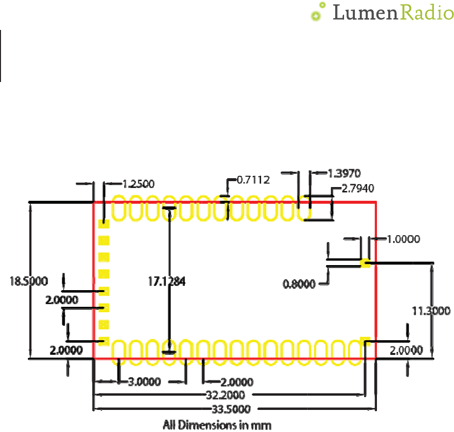
Mec
TiMo
Figure
hanic
a
RX RD
M
5: Mechan
i
a
l spe
c
M
i
cal specifi
c
c
ificati
c
ations
Ͳ29Ͳ
ons

Ͳ30Ͳ
Revision history
Document
revision Release
date Comment Status
A 2014-10-02 First release Released