Lumenetix CTM0-DDM0 Color Tuning Module User Manual
Lumenetix Inc Color Tuning Module Users Manual
Users Manual

THE TRUE AND PERFECT LIGHT
araya® LED Light Engine
CTM0 32 CTM0 19 CTM0 12
DDM0 32 DDM0 19 DDM0 12
Installation Guide
iii | araya® LED Light Engine Installation Guide
TABLE OF CONTENTS
1 Introduction 2
2 Heat Sinking 3
2.1 Compatible Heat Sinks
2.2 Mechanical Attachment of the Heat Sink
3 CTM Case Temperature Measurement 5
4 Secondary Optics 6
4.1 CTM0 12 Reflectors
4.2 DDM0 19 Reflectors
4.2.1 Attaching Reflectors
4.2.2 Compatible Reflectors
5 Power Supplies 8
6 DDM Wiring Diagrams 9
6.1 0-10V Control of Dimming / On/Off Line Voltage Switching
6.2 0-10V Control of Dimming / On/Off Class II Switching
7 CTM Wiring Diagrams 10
7.1 Wireless Operation of Dimming, CCT, Saturation and Hue
7.2 0-10V Control of Dimming / Wireless Operation of CCT, Saturation and Hue
7.3 0-10V Control of Dimming and Preset Scenes of CCT, Saturation and Hue
7.4 0-10V Control of Dimming and Continuous CCT

araya® LED Light Engine Installation Guide | 2
This Installation Guide covers the following araya® Color Tuning Modules (CTM) and Dynamic Dimming Modules™ (DDM)
CTM0 32
•
DDM0 32
CTM0 19
•
DDM0 19
CTM0 12
•
DDM0 12
For complete Color Tuning Module specifications, please visit: www.lumenetix.com/downloads
This Installation Guide covers heat sinking, case temperature measurement, secondary optics, power supply and wiring diagrams
for wireless operation using the Lumenetix Light Commissioning Tool, industry standard 0-10V wired controls or a hybrid
operation that combines hard wired and wireless control.
The CTM Source diffuser is fragile. Avoid touching the diffuser
during handling and assembly.
Do not operate the CTM while it is resting face down against
a table or other solid surface.
For long term, reliable operation, proper heat sinking is critical.
1 INTRODUCTION
3 | araya® LED Light Engine Installation Guide
2 HEATSINKING
The CTM light module requires an external heat sink in order to ensure proper operating temperature of the LEDs. The CTM
has a conductive aluminum case and an efficient thermal path to the LED array. These features promote efficient thermal
management and allow for a simple heat sink design in most applications.
Examples of heat sinking methods are: cast or extruded heat sinks, an aluminum panel or aluminum fixture housing. Both
carbon and stainless steel are much less efficient at transferring heat than aluminum and therefore are not recommended as
heat sink material. The heat sink mounting surface should be flat and smooth. Metal-to-metal contact surfaces will result in best
performance; anodized or unfinished mounting surfaces are recommended. Mounting the CTM on a painted aluminum surface
will reduce the performance of the heat sink material.
2.1 Compatible Heat Sinks
The following tables list heat sinks models that have compatible form factors and thermal resistance characteristics for use
with the CTM. The thermal resistances assume an approximate ambient temperature of 25C. The heat sinks listed here
are suggestions only. The heat sink must be evaluated and temperature tested in the fixture application at applicable
ambient temperatures.
MechaTronix (round)
Part Number Dia. (mm) Height (mm) Thermal Resistance (°C/W)
LSB9950 99 50 1.3 – 1.5
LSB9980 99 80 1.2 – 1.4
Additional product information at www.led-heatsink.com
Nuventix (round)
Part Number Description Input Voltage Dia. (mm) Height (mm) Thermal Resistance (°C/W)
HP30S-CALBL-001 Heat Sink 95 39 2.5 (heat sink only)
SPARS-CM005-002 (1) Cooler 5V 1.0 – 1.55
SPARS-CM012- 002 (1) Cooler 12V 1.0 – 1.55
Additional product information at www.nuventix.com
No current commercial 24V power supply offerings with dual voltage out for Nuventix Synjet cooler (24V out w/ 5V or 12V out).
Requires DC/DC voltage adaptor without dual voltage output.
Aavid Thermalloy Heat Sink Extrusions (square/rectangular)
Part Number Width (mm) Length Height (mm) Thermal Resistance (°C/W)
67590 88 88 31 1.5 – 1.7
61085 136 85 33 1.4 – 1.6
Additional product information at www.aavid.com
araya® LED Light Engine Installation Guide | 4
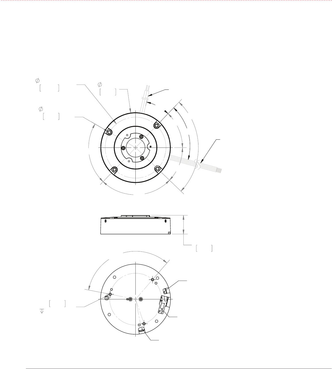
2.2 Mechanical Attachment of the Heat Sink
The CTM/DDM light engine has two options for heat sink mounting:
1. Front mount using four 4-40 or M2.5 screws
2. Rear mount using three M3 screws
Figure 1: Rear Mount of CTM/DDM to Heat Sink
81mm
3.2in
4X FRONT MOUNT
3.10mm
.12in
(FOR 4-40 UNC
OR M2.5 SCREWS)
90°
90°
77°
44°
46°
70.53mm
2.78in
B.C.
31°
61°
DIMMING LEADS:
1 PURPLE, 1 GREY, 24 GA
CCT LEADS:
1 BLUE, 1 WHITE, 24 GA
(NOT USED ON DDM)
610mm (24in) LONG,
6mm (.25in) STRIP LENGTH
POWER LEADS: 1 RED, 1 BLACK, 22 GA
610mm (24in) LONG, 6mm (.25in) STRIP LENGTH
22mm
.85in
3X M
3mm
.12in
x0.5
5mm (.2in)
REAR MOUNT
3X 120°
POWER LEAD PORT
CONTROL LEAD PORT
RESERVED FOR FUTURE USE
5 | araya® LED Light Engine Installation Guide
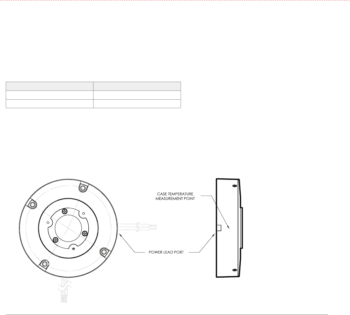
The thermal management characteristics of the heat sink used with the CTM should be validated by measuring its case
temperature. This test should be done with the CTM installed in the fixture at ambient temperature and air flow conditions similar
to the end-use installation.
araya® CTMs are available with two ranges: 1600 – 4000K and 2700 – 6000K. The power draw of the CTM varies by approximately
one watt over the CCT range with peak power draw occurring at the CCT shown in the following table. Depending on the CCT
range, the case temperature should be measured at the following CCT setting.
CCT Setting for Case Temperature Measurement
CTM CCT range CCT Setting to Measure Tcase
1600 – 4000K 2800K
2800 – 6000K 4400K
The proper case temperature measurement location is next to the exit for the power leads, see Figure 3. The temperature reading
should be made after the unit has reached steady state, where the case temperature levels out. It is recommended to design for a
case temperature of 70° C at maximum ambient temperature conditions
The CTM color tuning module has built-in over-temperature protection. It is designed to turn down the current to the LED array
when the case temperature reaches 75° C. This ensures the LEDs don’t exceed their maximum rated temperature.
3 CTM CASE TEMPERATURE MEASUREMENT
Figure 2: Case Temperature Measurement Point
araya® LED Light Engine Installation Guide | 6
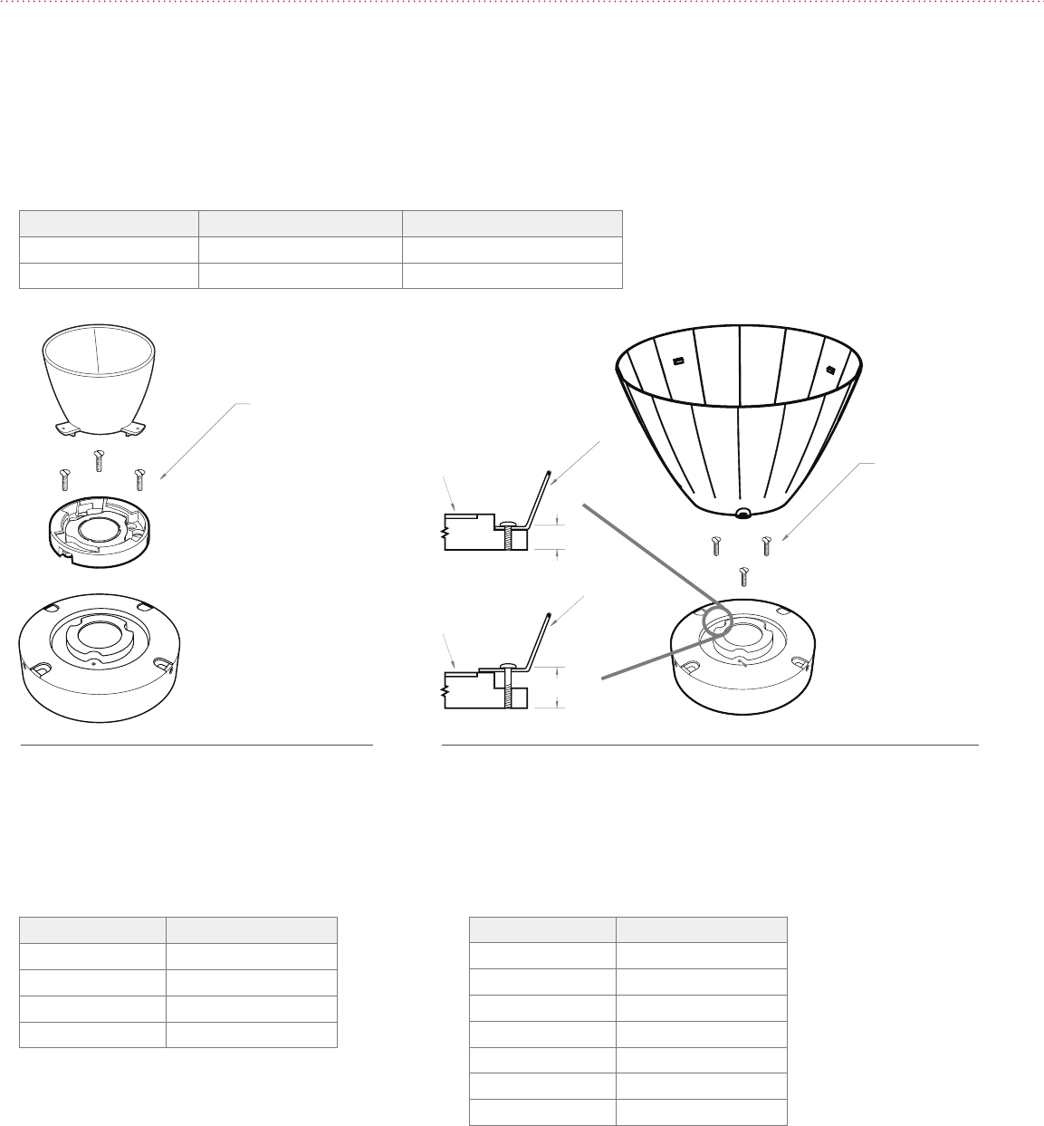
4.1 CTM0 12 Reflectors
The CTM0 12 accepts the Lumenetix sReflector and mReflectors and has attachment features to accept other reflectors.
4 SECONDARY OPTICS
Figure 4: Side Mount Attachment of the sReflector and the mReflector
Figure 3: CTM0 12 Front Attaching Reflectors
NOTE: mReflector shown,
assembly similar for sReflector
REFLECTOR
M1.8
THREAD FORMING
SOURCE APERTURE
5 mm (0.187")
Reflector Type Fastener Specification
sReflector 0 – 80 x ¼" Flathead
mReflector M1.8 x 6 Thread Forming Flathead
7 | araya® LED Light Engine Installation Guide
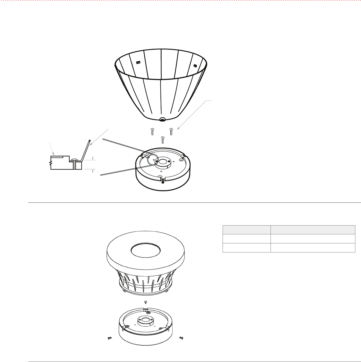
4.2 CTM0 19 Reflectors
4.2.1 Attaching Reflectors
The CTM0 19 accepts the twist-to-lock reflectors with an attachment collar. The module also has provisions for front mount
reflectors. The fastener specifications are shown in the following table while mounting hole locations are shown in Figures 6 & 7.
CTM0 19 Secondary Optics Fastener Specifications
CTM0 19 Reflector Fastener specifications Screw length
Twist Lock w/ Collar 2 - 28 x 3/16, M1.8 x 5 5 mm (3/16")
Front Mount 2 - 28, M1.8 5 mm (3/16") or 10 mm (3/8")
M1.8 x 5, 2 - 28 x 3/16
THREAD FORMING
USE FLAT HEAD SCREWS REFLECTOR
SOURCE APERTURE
REFLECTOR
5 mm (0.187")
10 mm (0.375")
SOURCE APERTURE
2 - 28 OR M1.8
THREAD FORMING
Figure 5: CTM0 19 Twist-Lock Style Reflectors with
attachment collars
Figure 6: CTM0 19 Front Attaching Reflectors
4.2.2 Compatible Reflectors
CTM0 19 Compatible Twist-Lock Reflectors
Vendor: Diffractive Optics, www.diffractive-optics.com
Part Number Beam Angle (degrees)
P6680 40
P6645 60
P7879 40
P6764 60
CTM0 19 Compatible Front Mount Reflectors
Vendor: Alux-Luxar, www.alux-luxar.com
Part Number Beam Angle (degrees)
XLC 400 28
XLC 500 26
XLC 800 42
XLC 110 0 27
XLC 1300 22
XLC 1400 25
XLC 1500 53
araya® LED Light Engine Installation Guide | 8
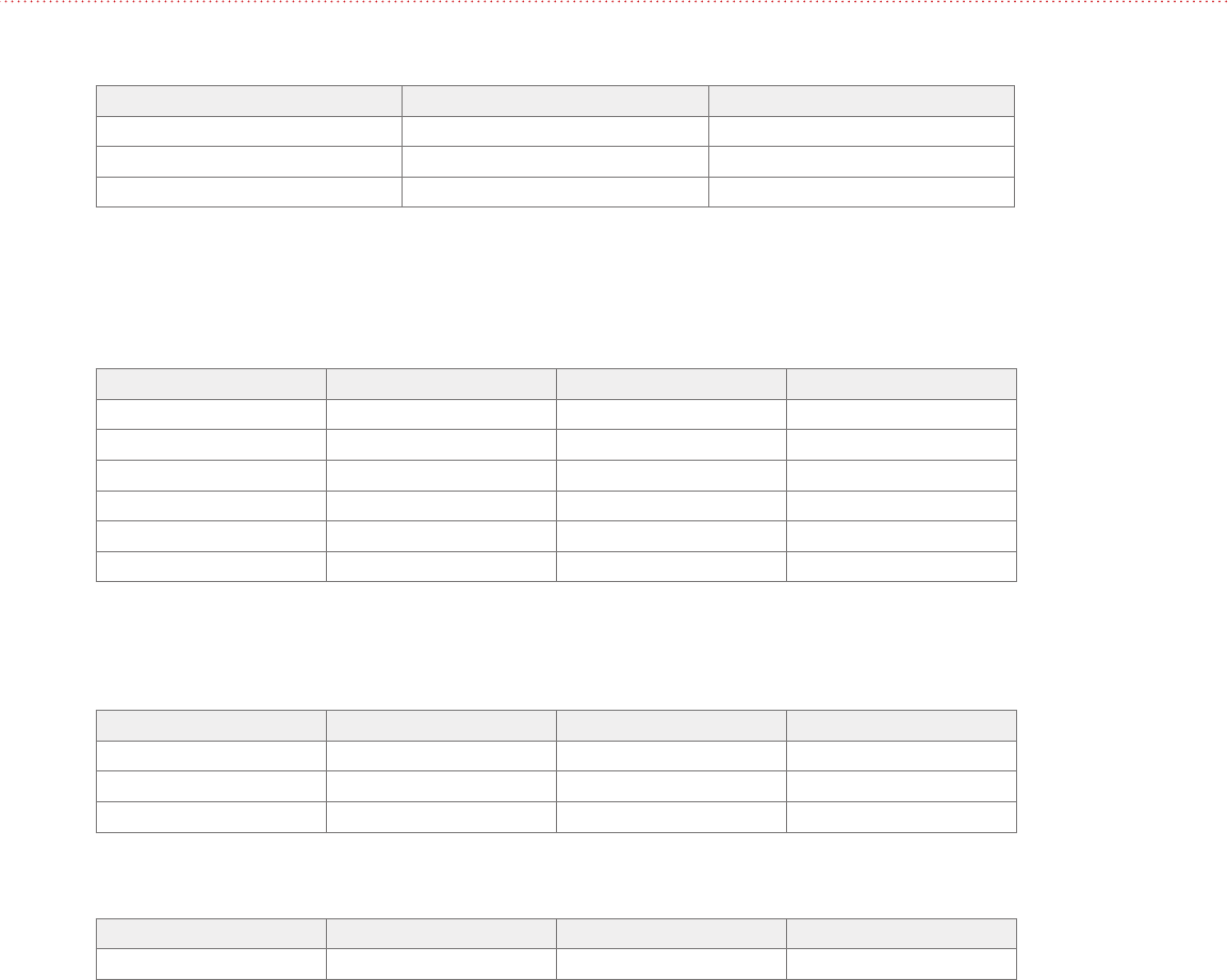
Recommended Power Supplies
Vendor: Philips
Part Number Qty of Units Powered Input Voltage Connection type
LED120A1400C24F 1120V Terminal block
LED120A0024V18F 1120V Terminal block
913700625082 1 207V – 264V Flying leads
INTA0024V28FLO 2 120V – 277V Flying leads
INTA0024V41FO 3 120V – 277V Flying leads
LED120A0024V10F* 1120V Terminal block
* DDM 20W only
Vendor: Osram Sylvania
Part Number Qty of Units Powered Input Voltage Connection type
OT30/120/24 1120V Flying leads
OT75W/24V/UNV 2120 – 277V Flying leads
OT96W/24V/UNV 3120 – 277V Flying leads
Vendor: Tridonic
Part Number Qty of Units Powered Input Voltage Connection type
LED 035/24 E020 1 108V – 264V Terminal block
General Requirements
Description CTM, DDM 25W DDM 20W
Voltage Output 24V DC 24V DC
Current Output 1.25 A per module 1.0 A per module
Component Listing Class 2 Class 2
5 POWER SUPPLY REQUIREMENTS
9 | araya® LED Light Engine Installation Guide
INPUT
10 V
0 V
VIOLET
GREY
COMMON
DIMMING
100%
5%
0-10 V CONTROLLER WITH LINE VOLTAGE SWITCH
ARAYA DDM LIGHT ENGINE
24V DC POWER SUPPLY
25W 1.25 CAPACITY / DDM
20W 1.0A CAPACITY / DDM
NEUTRAL IN
HOT LINE IN
INPUT
10 V
0 V
VIOLET
GREY
COMMON
DIMMING
100%
5%
0-10 V CONTROLLER WITH CLASS II SWITCH
ARAYA DDM LIGHT ENGINE
24V DC POWER SUPPLY
25W 1.25 CAPACITY / DDM
20W 1.0A CAPACITY / DDM
LINE IN
VOLTAGE
24V IN
SWITCHED OUT
Lead Color and Input
Lead Color Input
Red Positive 24V
Black Negative
Violet 0-10V Dimming
Gray Common
Lead Color and Input
Lead Color Input
Red Positive 24V
Black Negative
Violet 0-10V Dimming
Gray Common
6 DDM WIRING DIAGRAMS
Figure 7
Figure 8
6.1 0-10V Control of Dimming / On/Off Line Voltage Switching
6.2 0-10V Control of Dimming / On/Off Class II Switching
Note:
1. CTM sources current to
0-10V control at 0.2mA
nominal capacity.
Note:
1. CTM sources current to
0-10V control at 0.2mA
nominal capacity.
araya® LED Light Engine Installation Guide | 10
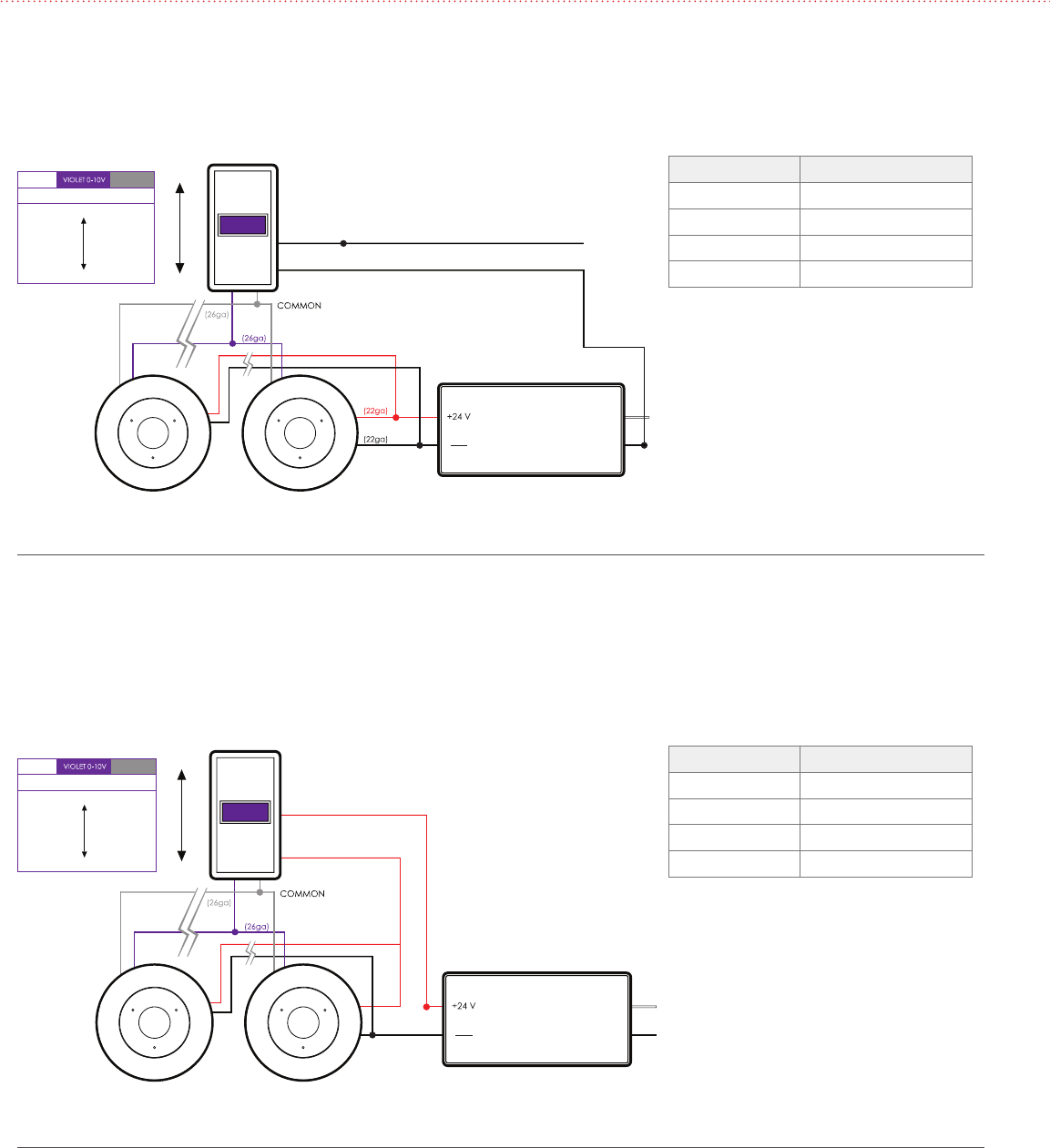
INPUTINPUT
CCT / SAT+HUEDIMMING
100%
5%
LCT
LCT WIRELESSLCT WIRELESS
INPUTINPUT
10 V
0 V
VIOLET
GREY
CCT / SAT+HUE
COMMON
DIMMING
100%
5%
0-10 V CONTROLLER LCT
LCT WIRELESS
Lead Color and Input
Lead Color Input
Red Positive 24V
Black Negative
Violet Ground to Common
Gray Common
White Common
Blue Ground to Common
Lead Color and Input
Lead Color Input
Red Positive 24V
Black Negative
Violet 0-10V Dimming
Gray Common
White Common
Blue Ground to Common
7 CTM WIRING DIAGRAMS
Figure 9
7.1 Wireless Operation of Dimming, CCT, Saturation and Hue
Figure 10
7.2 0-10V Control of Dimming / Wireless Operation of CCT, Saturation and Hue
Note:
1. CTM sources current to
0-10V control at 0.2mA
nominal capacity.
11 | araya® LED Light Engine Installation Guide
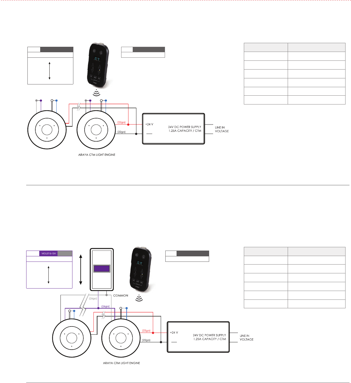
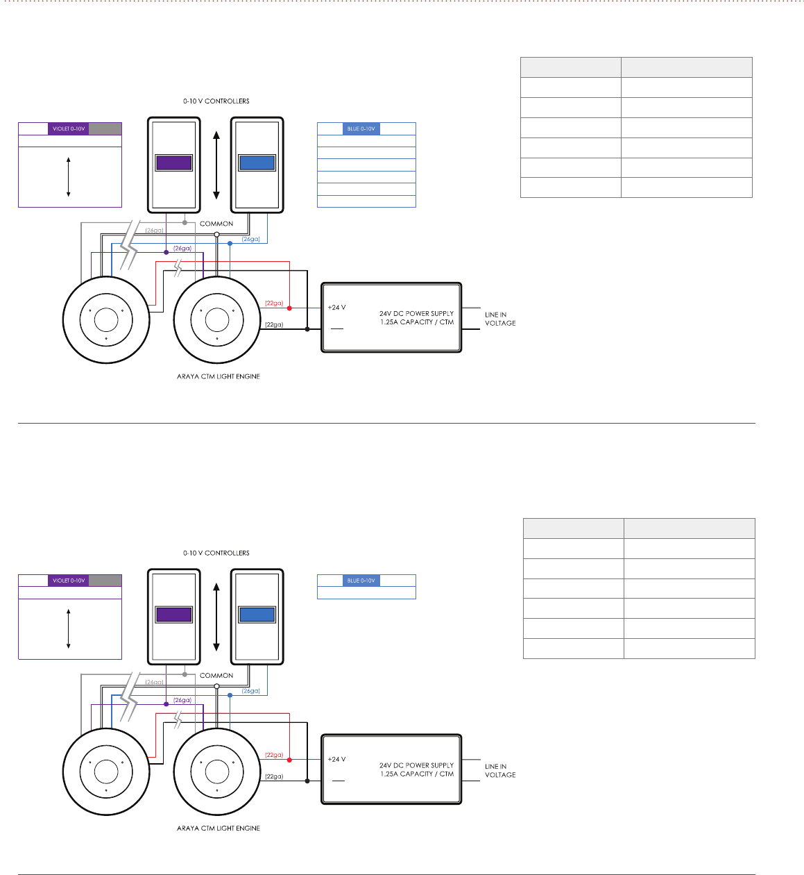
COMMONINPUTINPUT 10 V
0 V
VIOLET
GREY
WHITE
BLUE
PRESETS
SCENE 5
SCENE 4
SCENE 3
SCENE 2
SCENE 1
COMMON
DIMMING
100%
5%
COMMONINPUTINPUT 10 V
0 V
VIOLET
GREY
WHITE
BLUE
Continuous CCT
COMMON
DIMMING
100%
5%
Fig ure 11
Figure 12
7.3 0-10V Control of Dimming and Preset Scenes
of CCT, Saturation and Hue
7.4 0-10V Control of Dimming and Continuous CCT
Notes:
1. Preset scenes are commissioned and
activated using the LCT. See LCT
operating instructions.
2. If 0-10V control is not being used for
dimming, the violet control lead must
be grounded to gray common lead.
3. CTM sources current to 0-10V control
at 0.2mA nominal capacity.
Notes:
1. If no preset scenes are activated using
the LCT, the CTM defaults to 0-10V
control of the continuous CCT range.
2. If 0-10V control is not being used for
dimming, the violet control lead must
be grounded to gray common lead.
3. CTM sources current to 0-10V control
at 0.2mA nominal capacity.
Lead Color and Input
Lead Color Input
Red Positive 24V
Black Negative
Violet 0-10V Dimming
Gray Common
White Common
Blue 0-10V Presets
Lead Color and Input
Lead Color Input
Red Positive 24V
Black Negative
Violet 0-10V Dimming
Gray Common
White Common
Blue 0-10V CCT

Lumenetix Inc.
4742 Scotts Valley Drive
Scotts Valley CA 95066
87 7.8 05 .728 4
www.lumenetix.com
Revised 01.24.14
Specifications subject to
change without notice