Luminex DH7061 LED Motion Sensor Security Light with Wi-Fi Camera User Manual DH7061
Luminex International Co., Ltd LED Motion Sensor Security Light with Wi-Fi Camera DH7061
Luminex >
15_DH7061 UserMan
Questions, problems, missing parts?
Before returning to your retailer, call our customer service at 1-800-887-6326
Monday – Friday 9:00 a.m. – 5:00 p.m. CST
Page 1 of 11
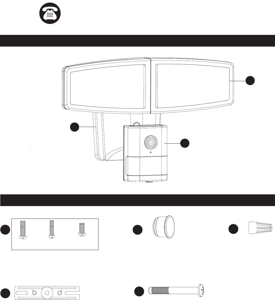
PACKAGE CONTENTS
OUTDOOR SECURITY LIGHT
Model Number:
Fixture Mounting Screw
X1
Wire Nut
X2
HARDWARE CONTENTS Note: Hardware not shown actual size.
A
C
B
AA
DD
CC
BB
EE
Mounting Screw
X2
Mounting Strap
X1
Decorative cover
X1
#8/32 X 1/2 in #6/32 X 1/2 in #10/24 X 1/4 in
DH7061
Before beginning assembly, installation or operation of product, make sure all parts are present. Compare parts with
package contents list and diagram on previous page. If any part is missing or damaged, do not attempt to assemble,
install or operate the product. Contact customer service for replacement parts.
Tools Required for Assembly (not included): Screwdriver, Phillips Screwdriver, Pliers, Electrical Tape, Wire Cutters,
Safety Glasses, Ladder, Wire Stripper.
Page 2 of 11
Please read and understand this entire manual before attempting to assemble, operate or install the product.
WARNING
Ɣ Turn off electricity at main fuse box (or circuit breaker box) before beginning installation by removing fuse (or switching
off circuit breaker).
Ɣ Be careful not to damage or cut the wire insulation (covering) during fixture installation. Do not permit wires to contact
any surface having a sharp edge. To do so may damage or cut the wire insulation, which could cause serious injury or
death from electric shock.
Ɣ LED electronics can be damaged by electro static discharge (ESD)shock. Before installation, discharge yourself by
touching a grounded bare metal surface to remove this hazard. To avoid damage, do not touch the LED module.
CAUTION
Ɣ All electrical connections must be in agreement with local codes, ordinances or the national electric code (NEC).
Contact your municipal building department to learn about your local codes, permits and/or inspections.
Ɣ Risk of fire – most dwellings built before 1985 have supply wire rated for 140°F/60ºC. Consult a qualified electrician
before installation.
Ɣ Only general ON/OFF wall switch applies for this fixture, the dimmable wall switch shouldn’t be required.
Maximum Wattage: 36 W
Working Temperature Range: -4ºF ~ 113ºF
PREPARATION
SAFETY INFORMATION
ASSEMBLY INSTRUCTIONS
Important to Know
1. This fixture requires a 120 VAC, 60 Hz power source.
2. For general safety and to avoid any possible damage to the sensor, be sure the power is switched "off" before
adjustment.
3. Motion sensor: turns light ON automatically when motion is detected and turns light OFF automatically when motion
stops.
4. Photocell keeps the light OFF during daylight hours.
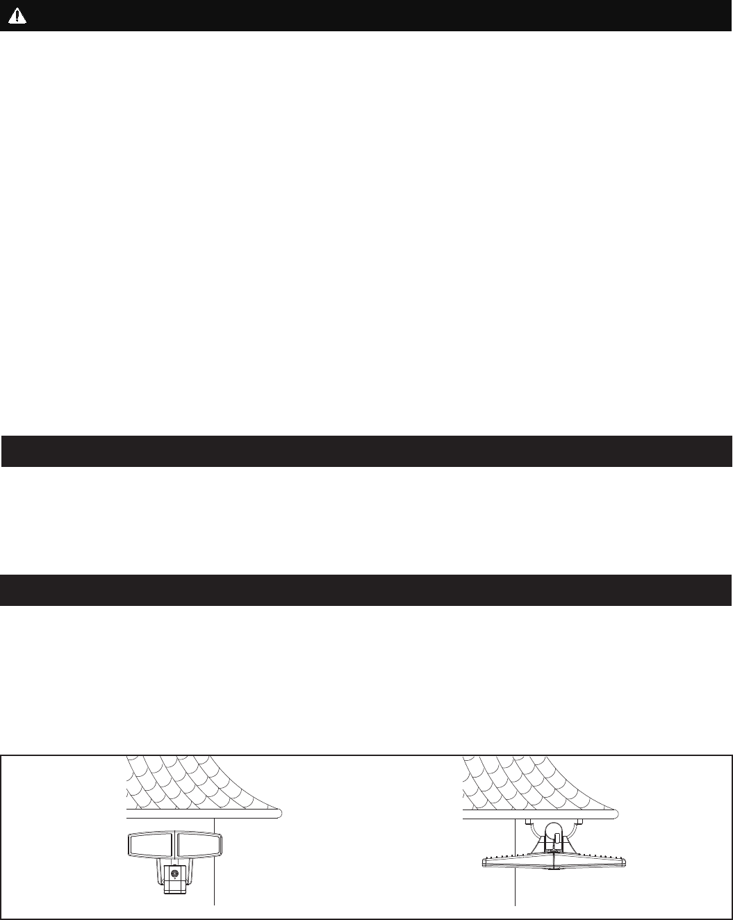
Note: Fixture can be wall mounted or eave mounted.
Wall Mounted Eave Mounted
Light fixture and sensor should be mounted as shown above when installed (depending upon type of installation)
Before installing the light fixture under an eave, the sensor head must be rotated as shown in the next two steps for
proper operation and to avoid the risk of electrical shock.
Page 3 of 11
ASSEMBLY INSTRUCTIONS (continued)
Camera
Back Plate
4. With silicone caulking compound
(not included), caulk completely
around where the back plate of the
light fixture(A) meets the wall
surface.
CAUTION: Be sure to caulk
completely where the back
plate meets the wall surface to prevent water from
seeping into the outlet box.
Turn on the power at fuse or circuit box.
Camera
1
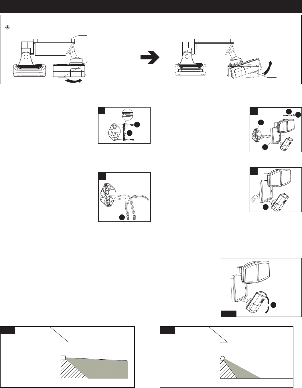
For eave mounted only:
5RWDWHWKHVHQVRUKHDGFORFNZLVHÛKRUL]RQWDOO\DQGWKHQWLOWDQJOHSURSHUO\
Turn off the power at fuse or circuit box.
1. Install the mounting strap(BB) to
the outlet box with the stamped
word “FRONT” facing away from
the outlet box, using two mounting
screws(AA) that best fit the outlet
box. (Choose one matching pair of
suitable mounting screws from the
3 pairs provided)
Installation Steps
FRONT
3
4
2
2. Connect the fixture black wire to
the house black wire and the
fixture white wire to the house
white wire using wire nuts(EE)
provided.
Carefully tuck the wires back into
the outlet box.
Adjusting the Sensor Head:
1. a: Aim sensor head(C) toward desired detection area, maintaining a 5° - 40°
downward angle to allow moisture to drain. (See Fig.1)
Note: Make sure sensor head is positioned with camera facing towards the
ground.
b: You can rotate the sensor head up and down to change the coverage area . Walk
through the detection zone at the farthest distance you wish to detect motion.
2. Range set too high may increase false triggering. (See Fig.2, Fig.3)
3. Attach the back plate of the light
fixture(A) to the mounting
strap(BB), and then secure it with
the fixture mounting screw(DD).
Push the decorative cover(CC)
firmly into the fixture mounting
screw(DD) hole on the light
fixture(A).
Fig. 1
Sensor Adjustment Lower For Short Coverage
Sensor Adjustment Higher For Long Coverage
Fig. 2 Fig. 3
BB
AA
EE
C
A
BB
A
DD CC
Page 4 of 11
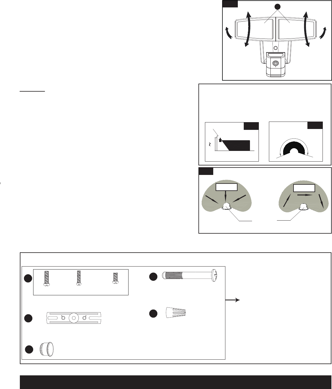
Spare Parts List:
The following parts are available for re-order if damaged or missing. Call us toll-free at 1-800-887-6326
CARE AND MAINTENANCE
Assembly Kit
5731MM (1 SET)
Fig. 4
Fixture Mounting Screw
X1
Wire Nut
X3
AA DD
CC
BB EE
Mounting Screw
X2
Mounting Strap
X1
Decorative cover
X1
#8/32 X 1/2 in #6/32 X 1/2 in
#10/24 X 1/4 in
ƔTo prolong the original appearance, clean the light fixture with clear water and a soft, damp cloth only.
ƔDo not use paints, solvents, or other chemicals on this light fixture. They could cause a premature deterioration of the
finish. This is not a defect in the finish and will not be covered by the warranty.
Adjusting the Light Head:
1. Gently grasp the light heads(B) and tilt them up or down, left or right to
DGMXVWWKHOLJKWFRYHUDJHDUHD.HHSWKHOLJKWKHDGVDWOHDVWÝPP
away from the sensor. (See Fig.4)
.HHSWKHOLJKWKHDGVÛEHORZKRUL]RQWDOWRDYRLGZDWHUdamage and
electrical shock.
Notes:
1. The sensitivity of the motion sensor will increase as the
environmental temperature gets cooler. You may wish to make
adjustments when the season changes. For best performance,
gently clean the lens with a soft cloth every 1 or 2 months to
assure maximum sensitivity.
2. For best performance, install fixture at least 8 feet above the
ground. At such a height, the fixture will provide a detection
distance of up to 70 feet at 77 degrees Fahrenheit. (See Fig.5)
3. The sensor detects movement across a detection range of 240
degrees. (See Fig.6)
4. The sensor will be more sensitive to motion across its detection
path than motion directly towards it. (See Fig.7)
5. To reduce possible nuisances, do not mount the fixture near a
heat source like an air conditioner, vent or furnace exhaust, or in
a direction facing any reflecting object or other light source.
25'
8.0'
12.0'
70'
Where you install your fixture is important:
Be sure the light is mounted straight on the wall
or eave; otherwise, the detection distance may
be limited.
Fig. 5 Fig. 6
Motion
Least sensitive
Motion
Most sensitive
Sensor
Fig. 7
240'
B
Page 5 of 11
TROUBLESHOOTING
1) The light does not come on at all:
a. Make sure the wall switch and circuit breaker are on.
b. Make sure the wiring is correct.
c. Cover the sensor with dark color cloth to verify that the ambient light level is not too high.
2) The light comes on for no apparent reason:
a. Re-aim the motion sensor.
b. Decrease the sensitivity setting.
c. Do not use a dimmer or timer to control the light fixture. Replace the dimmer or timer with a standard on/off wall
switch.
3) The light flashes on and off:
a. Reposition the motion sensor.
If unable to fix any of the above issues, please consult a certified electrician.
Questions, problems, missing parts?
Before returning to your retailer, call our customer service at 1-800-887-6326
Monday – Friday 9:00 a.m. – 5:00 p.m. CST
FIVE-YEAR LIMITED WARRANTY: If, during normal use, this PATRIOT LIGHTING lighting fixture breaks or fails
due to a defect in material workmanship within five (5) years from the date of original purchase, simply bring this
lighting fixture with the original sales receipt back to your nearest MENARDS retail store. At its discretion, PATRIOT
LIGHTING agrees to have the product or any defective part(s) repaired or replaced with the same or similar PATRIOT
LIGHTING product or part free of charge, within the stated warranty period, when returned by the original purchaser
with original sales receipt. This warranty; (1) excludes expendable parts including but not limited to light bulbs; (2) does
not cover damage that has resulted from abuse or misuse; and (3) does not cover any losses, labor, injuries to
persons/property or costs. This warranty does give you specific legal rights and you may have other rights, which vary
from state to state.
R
R
R
R
FCC Statement
NOTE: This equipment has been tested and found to comply with the limits for a Class B digital device,
pursuant to part 15 of the FCC Rules. These limits are designed to provide reasonable protection against
harmful interference in a residential installation. This equipment generates uses and can radiate radio
frequency energy and, if not installed and used in accordance with the instructions, may cause harmful
interference to radio communications. However, there is no guarantee that interference will not occur in a
particular installation. If this equipment does cause harmful interference to radio or television reception,
which can be determined by turning the equipment off and on, the user is encouraged to try to correct the
interference by one or more of the following measures:
- Reorient or relocate the receiving antenna.
- Increase the separation between the equipment and receiver.
- Connect the equipment into an outlet on a circuit different from that to which the receiver is connected.
- Consult the dealer or an experienced radio/TV technician for help.
Changes or modifications not expressly approved by the party responsible for compliance could void the
user's authority to operate the equipment. This device complies with Part 15 of the FCC Rules. Operation is
subject to the following two conditions:
(1) this device may not cause harmful interference, and
(2) this device must accept any interference received, including interference that may cause undesired
operation.
Page 6 of 11
B
USER GUIDE
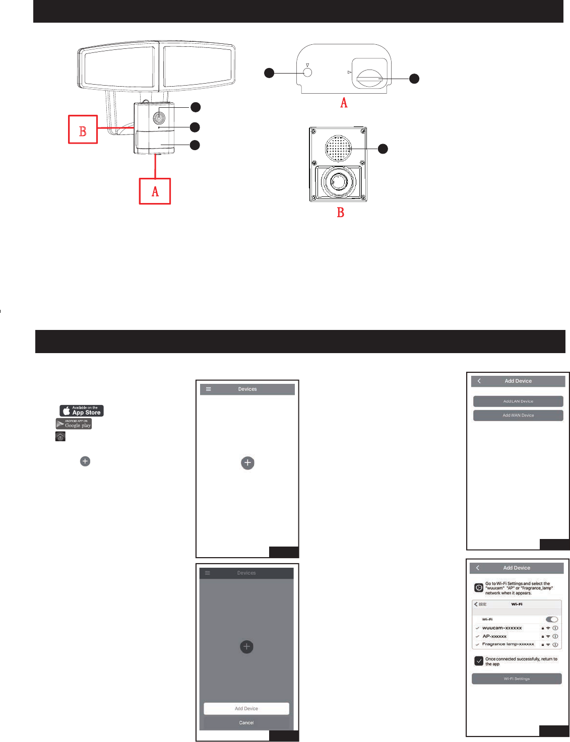
The Appearance Introduction of Product:
Setting for light through mobile device.
Before you start
Search “instaHome” on IOS APP
store or Android Google
Play , install the instaHome
APP onto the mobile device and
click it.
Fig.1
Fig.2
Fig.3
Fig.4
1. Select “ ”.
2. Select “Add Device”.
3. Select “Add LAN Device”.
1. Camera
2. LED Indicator
3. Sensor and Photocell
4. Reset
5. SD Card Slot
6. Build-In Speaker
4. Select “Wi-Fi Settings”.
RESET
Micro SD
1
3
5
4
2
6
Page 7 of 11
USER GUIDE (Continued)
Fig.5
Fig.6
Fig.7
Fig.9
Fig.10
Fig.11
Fig.12
Fig.8
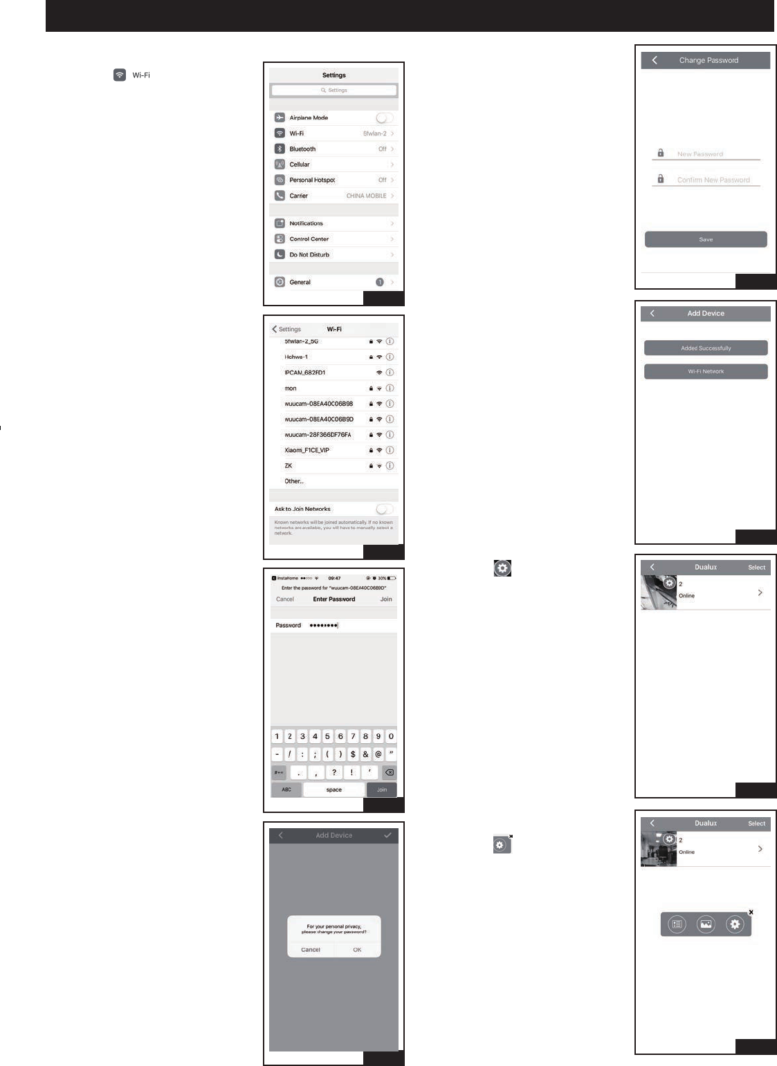
6. Select specified light device’s
hot spot started with “wuucam-”.
5. Select “ ”.
7. Input password, the default
password is:12345678, it can
not be changed. Then click
“Join”.
9. Set new light device password
and confirm it, and then click
“OK”, skip to Fig.11.
11. Select “ ”.
8. Select “OK” to change the light
device password and skip to
Fig.9.
Select “Cancel”, the default
password is 888888, and then
skip to Fig.10.
10. Select “Added Successfully”,
skip to Fig.11.
12. Select “ ” in pop-up box.
Page 8 of 11
Fig.13
Fig.14
Fig.15
Fig.16
USER GUIDE (Continued)
Fig.17
Fig.18
Fig.19
Fig.20
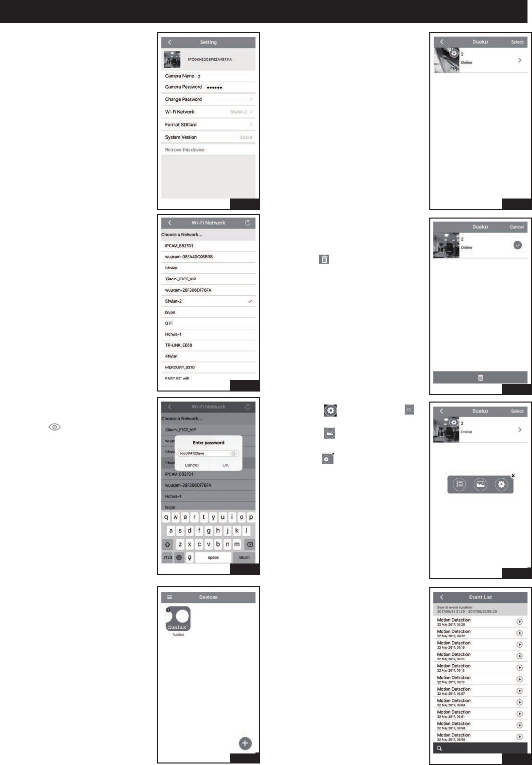
13. Select “ Wi-Fi Network” .
14. Choose an existing WiFi
Network.
15. Input password, it is the indoor
existing WiFi password,
press “ ” that can show
the password, and then
click “OK”, wait the prompt
tone that the light device has
connected WiFi successfully.
16. Select “Dualux” icon.
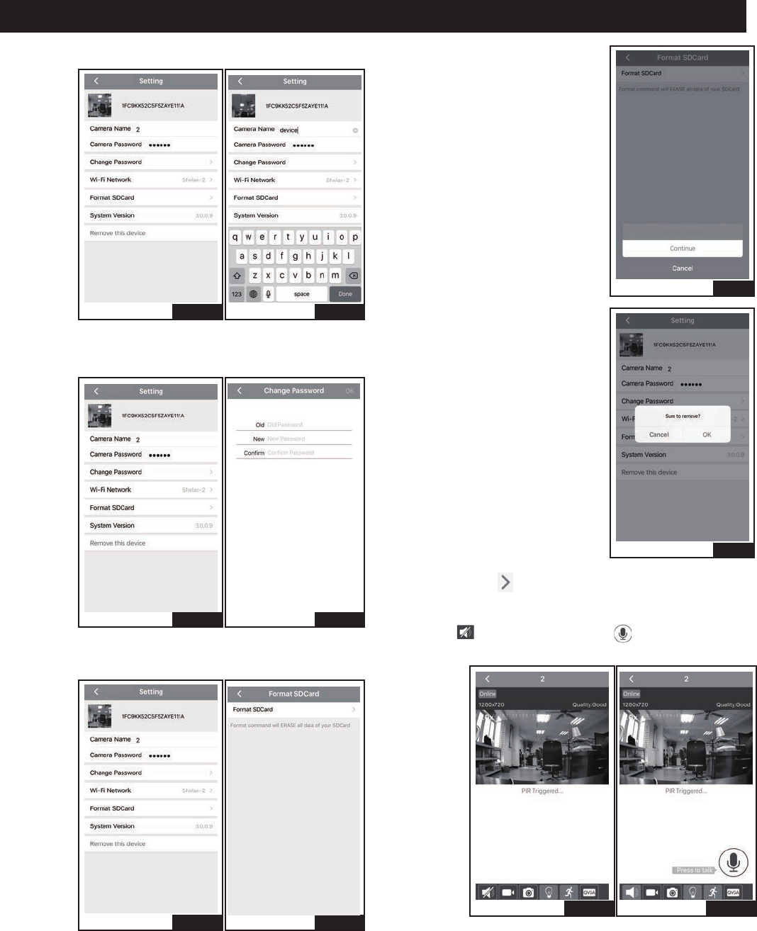
17. Select top right “Select”.
18. If want to remove this light
device, check the light device
on the right, and then
select “ ” to remove this light
device.
19. Select “ ”, then select “ ”
in pop-up box, skip to Fig.20.
Select “ ” to access user
phone picture.
Select “ ”, skip to Fig.21.
20. It is showed event video lists
which are saved in light device
SD.
Page 9 of 11
Fig.21-b
Fig.22-b
Fig.23-b
Fig.21-a
Fig.23-a
Fig.22-a
USER GUIDE (Continued)
Fig.24
Fig.25
21. Select “Camera Name” to change light device name.
22. Select “Camera Password”, set new password and
confirm it.
23. Select “Remove this device” , then select “Format
SD Card”.
24. Select “Continue”.
25. If want to remove videos saved
in SD card, select “OK”, or
select “Cancel”.
Fig.26-bFig.26-a
26. Select Fig.17 “ ”, when the PIR is triggered, it is
alarmed by phone message, if do not want to receive
these messages, turn off the notice in phone setting.
Select “ ” for intercom, press “ ” to talk, and
release it can monitor video voice.
Page 10 of 11
USER GUIDE (Continued)
Fig.31
Fig.30-bFig.30-a
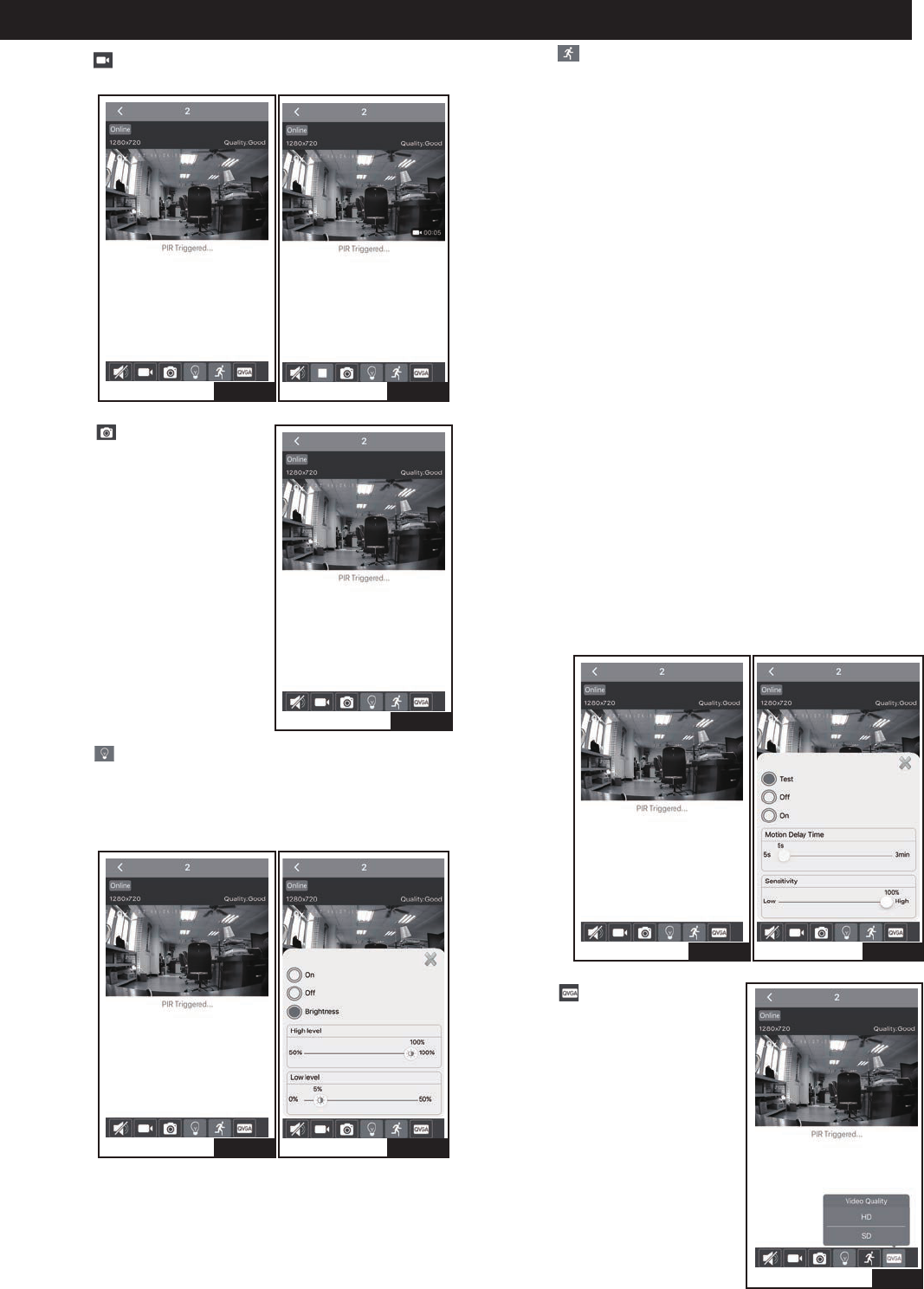
30. Select “ ”.
“Test” mode, on daytime and nighttime, the light turns
on and records video automatically when motion is
detected, and stays on as long as motion continues.
About 5 seconds after motion is no longer detected, it
turns off automatically and stops recording.
The time of recording video is 1minute 5 second at
least each time.
The detection distance is 5 feet to 70 feet.
“Off ” mode, the light device is turned off, and can not
be recorded video.
“ON” mode, at dusk, the light will turn to low level
brightness (0~50% brightness). The light will turn to
high level brightness (50%~100% brightness) when
motion is detected, and stay on as long as the motion
is continuing. When the motion stops, the light will
remain on for the predetermined time as you set
(5s ~ 3min), and then revert to low level brightness
(0~50% brightness). The light will turn off automatically
at dawn.
On daytime and nighttime, the light records video
automatically when motion is detected, and stays on as
long as motion continues. When the motion stops, the
light stops recording.
The time of recording video is 1minute 5 seconds at
least each time.
The detection distance is 5 feet to 70 feet.
Fig.27-bFig.27-a
Fig.28
Fig.29-bFig.29-a
27. Select “ ” for recording videos which are saved in
phone picture.
29. Select “ ”.
Select “ON”, the light device is turned on.
Select “OFF”, the light device is turned off.
Select “Brightness”, that can set the light device’s
high level brightness and low level brightness.
28. Select “ ” for taking photo,
the photos are saved in phone
picture.
31. Select “ ”, and choose video
quality, included HD and SD.
Page 11 of 11
Fig.34
Fig.32-bFig.32-a
USER GUIDE (Continued)
Fig.35
Fig.36
Fig.37
Fig.33-bFig.33-a
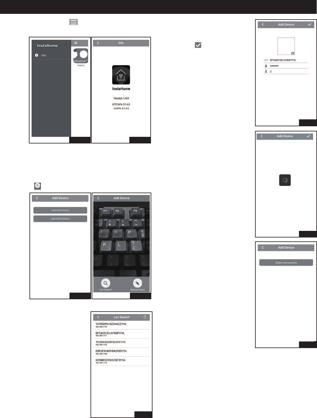
32. Select Fig.16 top left “ ”, and then select “info” to
show the APP version information.
WAN Device Connect.
the light device and the phone must be connected
the same WiFi.
33. Select “Add WAN Device”.
Select “ ”.
34. Select desired light device UID
shown in list.
35. Input password (input the
light device’s name or
not to do), and then click
top right “ ”.
37. Select “Added Successfully”,
then skip to Fig.16 automatically.
36. Search processing.