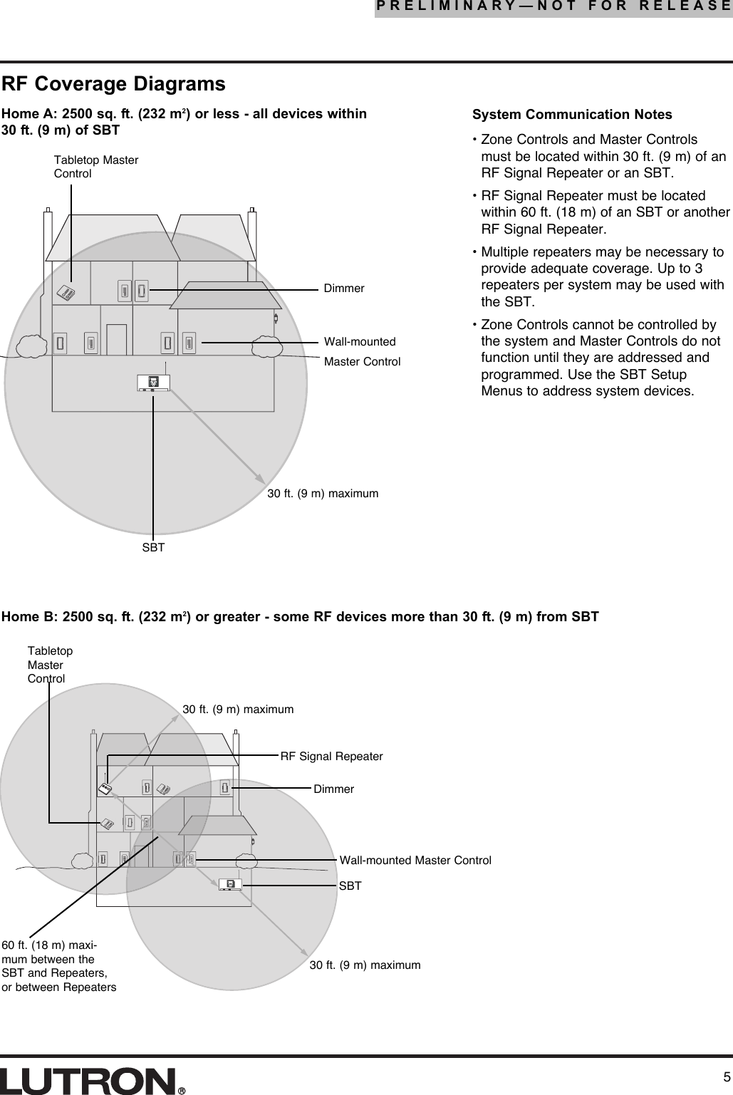
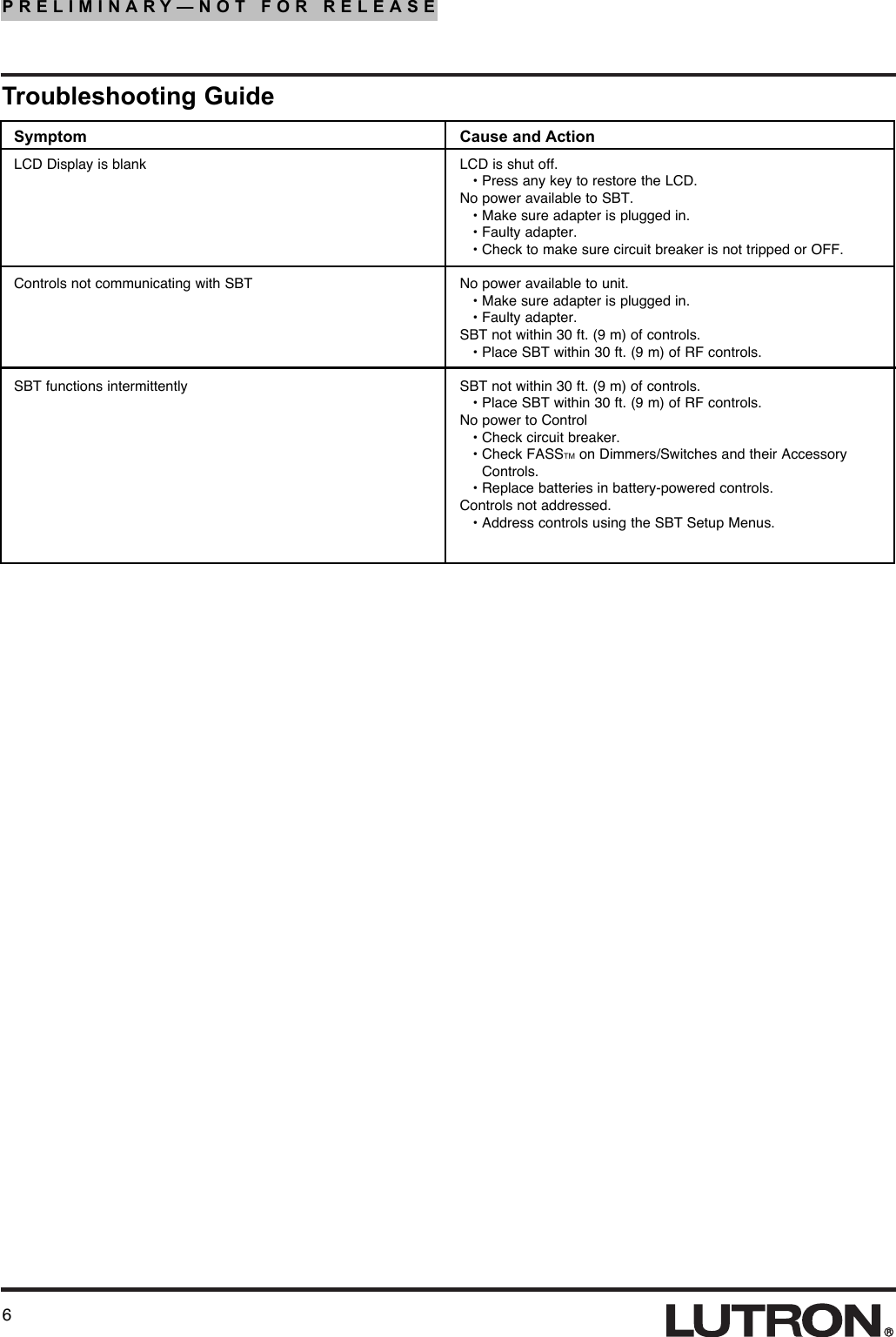
Lutron Electronics 0026 System Bridging Timeclock User Manual 043 xxx SBT

Lutron Electronics Company Inc System Bridging Timeclock 043 xxx SBT

Users Manual

1PRELIMINARY—NOT FOR RELEASEPlease Read Before InstallingSystem Bridging TimeclockTMRA-SBT, RB-SBT120/127 V    50/60 Hz (18 V    / 0.3 A adapter)Installation InstructionsOverviewThe System Bridging Timeclock (SBT) bridges twoRadioRA systems, providing a total of 64 Zone Controlsand 24 Master Controls. The SBT also provides an RS-232 interface, contact closure inputs, and an astro-nomic time clock.Each SBT covers approximately 2500 square ft. (232 m2) of living space.Up to 3 RF Signal Repeaters may be used with the SBTfor each system to extend the communications range.Important NotesCodes: Install in accordance with all local andnational electrical codes.Power: Use only the adapter provided by Lutron withthe SBT.Caution - Using an adapter not rated forthe following specifications could damagethe SBT and possibly overheat the adapter.• Input: 120/127 V    50/60Hz• Output: 18 V   / 0.3 A Class 2Environment: Ambient operating temperature: 0-40°C, 32-104°F, 0-90% humidity, non-condensing.Indoor use only.Cleaning: To clean, wipe with a clean damp cloth.DO NOT use any chemical solutions. Do not paintthe SBT.Mounting: DO NOT ground the SBT. DO NOTmount the SBT in a metal enclosure.RF Device Placement: Master Controls and ZoneControls that are to be controlled by the SBT mustbe located within 30 ft. (9 m) of the SBT or an RFSignal Repeater. Setup: The SBT will not function until it is addressedand programmed. See the System BridgingTimeclock Setup and Programming Guide.RA-SBTRB-SBT
4. Configure the SBT. Use the SBT display to setconfiguration.5. Connect Serial Link (if applicable). Connect astandard DB9 male connector to the RS-232 con-nector on the SBT for communications with otherequipment. 6. Connect external input closures (optional). TheSBT accepts three low-voltage dry contact clo-sures. Connect wiring for closures to input terminalblock if desired (see Wiring Diagram—page 3).         When using the input closures:Verify compatibility of external devices. The inputclosures are intended for use with devices thatprovide outputs in the form of dry contact closureoutputs. The input closures may be used withground-referenced, solid-state outputs if the out-puts have an on-state saturation voltage of lessthan 2 V    and an off-state leakage of less than 50 µA. Dry contact or solid-state outputs must becapable of switching 18 V    at 10 mA. The outputsmust stay in the closed or open states for at least40 msec in order to be recognized by the SBT. Ifthere is any question as to whether the contactclosure device is compatible with these specifica-tions, contact the manufacturer of that device.2PRELIMINARY—NOT FOR RELEASEInstallation1. Find a suitable location for the SBT. Place theSBT in a convenient and accessible location. SeeRF Coverage Diagrams on page 5.2. Mount the SBT. Mount SBT to wall using theappropriate mounting hardware provided (seeMounting Diagram). Orient the processor’s anten-na for optimal performance. For most installations,the antenna should be oriented vertically. Note:DO NOT ground the SBT. DO NOT mount the SBTin a metal enclosure.3. Apply power to the SBT.Verify LED lightswhen poweredPlug in powercord andadapter11.54"(293mm)8"(203mm)1.25"(32mm)6.16"(157mm)6.7"(170mm)0.70"(18mm)Front View(Port Cover removed)Side View5.77"(147mm)1.77"(45mm)DimensionsMounting ScrewMounting ScrewOptional Mounting ScrewMounting DiagramIncluded:Drywall Anchors (3)Mounting Screws (3)Masonry Anchors (3)Mounting Screws (3)Wall Anchors7"(178mm)
3PRELIMINARY—NOT FOR RELEASEContact Closure Input Wiring DiagramSBTPort Cover InstallationThe Port Cover can be removed for access to the Reset Button and Diagnostic LEDs. The cover is removed bygently pulling up on the front edge to disengage the snaps. Replace the cover by inserting the two tabs on theback of the cover into the slots on the SBT. Gently press down on the front edge to engage the snaps.SlotsTabTabPressDownInput 1Input 2SecurityInput
4PRELIMINARY—NOT FOR RELEASEOperationHome KeyMenuNavigationKeysDisplay PowerLEDPower In LEDKeyboard PortReset ButtonRS-232 LinkActivity LEDs1.  Home Key: Returns the user to the Home Screen.2.  Menu Navigation Keys: Used to navigate the variousmenus and screens for the processor.3.  RS-232 Link Activity LEDs: The LEDs will illuminatewhen there are any RS-232 signals being transmitted(TX LED) or received (RX LED) on that link.4.  RS-232 Port: Standard 9-Pin male connector for con-necting to an external control system (A/V system,HVAC, etc.).5.  Contact Closure Inputs: Used for control by externalsystems, such as A/V, Security, etc..6.  Reset Button: Used to reset the SBT.7.  Keyboard Port: Allows a computer keyboard to be con-nected to the SBT for ease of programming and naviga-tion. Standard PS/2 keyboard connector.LCD Display8.  RF Activity LEDs: The LEDs will illuminate when thereare any RF signals being transmitted (TX LED) orreceived (RX LED).9. Power Input Jack: Input jack for the 18 V    adapter.Center pin is positive.10. Power In LED: This LED illuminates when power fromthe adapter is present at the Power Input Jack.11. LCD Display: Displays programming and diagnosticinformation. The LCD Display will shut off after 60 min-utes of inactivity. To restore the display, simply pressany key.12. Display Power LED: This LED will illuminate when theLCD Display has power.312RS-232 Port 4ContactClosure Inputs567101112Power InputJack9PIN123456789Name   DescriptionDCD      Data Carrier DetectTXD      Transmit DataRXD      Receive DataDSR      Data Set ReadyGND     GroundDTR      Data Terminal ReadyCTS      Clear To SendRTS      Request To SendRI         Ring IndicateRF ActivityLEDs8
5PRELIMINARY—NOT FOR RELEASE##* Start StartP/N 292-153P/N 292153Tabletop MasterControlDimmer30 ft. (9 m) maximumSBT Wall-mountedMaster Control* Sta Sta*11223344Dimmer30 ft. (9 m) maximumSBT Wall-mounted Master ControlRF Signal Repeater30 ft. (9 m) maximum60 ft. (18 m) maxi-mum between theSBT and Repeaters,or between RepeatersRF Coverage DiagramsSystem Communication Notes• Zone Controls and Master Controlsmust be located within 30 ft. (9 m) of anRF Signal Repeater or an SBT. • RF Signal Repeater must be locatedwithin 60 ft. (18 m) of an SBT or anotherRF Signal Repeater. • Multiple repeaters may be necessary toprovide adequate coverage. Up to 3repeaters per system may be used withthe SBT.• Zone Controls cannot be controlled bythe system and Master Controls do notfunction until they are addressed andprogrammed. Use the SBT SetupMenus to address system devices.Home A: 2500 sq. ft. (232 m2) or less - all devices within30 ft. (9 m) of SBTHome B: 2500 sq. ft. (232 m2) or greater - some RF devices more than 30 ft. (9 m) from SBTTabletopMasterControl
6PRELIMINARY—NOT FOR RELEASETroubleshooting GuideSymptom Cause and ActionLCD is shut off.• Press any key to restore the LCD.No power available to SBT.• Make sure adapter is plugged in.• Faulty adapter.• Check to make sure circuit breaker is not tripped or OFF.No power available to unit.• Make sure adapter is plugged in.• Faulty adapter.SBT not within 30 ft. (9 m) of controls.• Place SBT within 30 ft. (9 m) of RF controls.SBT not within 30 ft. (9 m) of controls.• Place SBT within 30 ft. (9 m) of RF controls.No power to Control• Check circuit breaker.• Check FASSTM on Dimmers/Switches and their AccessoryControls.• Replace batteries in battery-powered controls.Controls not addressed.• Address controls using the SBT Setup Menus.LCD Display is blankControls not communicating with SBTSBT functions intermittently
7PRELIMINARY—NOT FOR RELEASENotes:
PRELIMINARY—NOT FOR RELEASELutron Electronics Co., Inc. 7200 Suter RoadCoopersburg, PA 18036-1299Made and printed in the U.S.A. 8/03 P/N 044-xxx Rev. ALIMITED WARRANTYLutron will, at its option, repair or replace any unit that is defective in materials or manufac-ture within two years after purchase. For warranty service, return unit to place of purchase ormail to Lutron at 7200 Suter Rd., Coopersburg, PA 18036-1299, postage pre-paid. Telephonethe Lutron Technical Support Center toll free at 800-523-9466. After the two year period, apro-rated warranty applies to this product until eight years after the purchase. For more infor-mation regarding this warranty contact your Lutron representative.THIS WARRANTY IS IN LIEU OF ALL OTHER EXPRESS WARRANTIES, AND THEIMPLIED WARRANTY OF MERCHANTABILITY IS LIMITED TO TWO YEARS FROM PUR-CHASE. THIS WARRANTY DOES NOT COVER THE COST OF INSTALLATION,REMOVAL OR REINSTALLATION, OR DAMAGE RESULTING FROM MISUSE, ABUSE,OR IMPROPER OR INCORRECT REPAIR, OR DAMAGE FROM IMPROPER WIRING ORINSTALLATION. THIS WARRANTY DOES NOT COVER INCIDENTAL OR CONSEQUEN-TIAL DAMAGES. LUTRON’S LIABILITY ON ANY CLAIM FOR DAMAGES ARISING OUTOF OR IN CONNECTION WITH THE MANUFACTURE, SALE, INSTALLATION, DELIVERY,OR USE OF THE UNIT SHALL NEVER EXCEED THE PURCHASE PRICE OF THE UNIT.This warranty gives you specific legal rights, and you may also have other rights which varyfrom state to state. Some states do not allow limitations on how long an implied warranty lasts,so the above limitation may not apply to you. Some states do not allow the exclusion or limi-tation of incidental or consequential damages, so the above limitation or exclusion may notapply to you. This product may be covered by one or more of the following U.S. patents: 4,835,343;4,954,768; 5,248,919; 5,399,940; 5,637,930; 5,736,965; 5,798,581; 5,838,226; 5,848,054;5,905,442; 5,982,103 and corresponding foreign patents. U.S. and foreign patents pending.Lutron, RadioRA, and the RadioRA logo are registered trademarks, and FASS is a trademarkof Lutron Electronics Co., Inc.©  2003 Lutron Electronics Co., Inc.Technical and Sales AssistanceIf you need assistance, call the toll-free LutronTechnical Support Center. Please provide exactmodel number when calling.(800) 523-9466 (U.S.A., Canada and the Caribbean)Other countries call:Tel:    (610) 282-3800Fax: (610) 282-3090Visit our Web site at www.lutron.comFCC InformationNote: This equipment has been tested and found to comply with the limits for a Class B digi-tal device, pursuant to Part 15 of the FCC rules. These limits are designed to provide rea-sonable protection against harmful interference in a residential installation. This equipmentgenerates, uses and can radiate radio frequency energy and, if not installed in accordancewith the instructions, may cause harmful interference to radio communications. However,there is no guarantee that interference will not occur in a particular installation. If this equip-ment does cause harmful interference to radio or television reception, which can be deter-mined by turning the equipment off and on, the user is encouraged to try to correct the inter-ference by one or more of the following measures: • Reorient or relocate the receiving antenna.• Increase the seperation between the equipment and receiver.• Connect the equipment into an outlet on a circuit different from that to which thereceiver is connected.• Consult the dealer or an experienced radio/TV technician for help.Caution: Changes or modifications not expressly approved by Lutron Electronics Co. couldvoid the user’s authority to operate this equipment.

Navigation menu