Lutron Electronics 0026 System Bridging Timeclock User Manual 043 xxx SBT
Lutron Electronics Company Inc System Bridging Timeclock 043 xxx SBT
Users Manual
1
PRELIMINARY—NOT FOR RELEASE
Please Read Before Installing
System Bridging TimeclockTM
RA-SBT, RB-SBT
120/127 V 50/60 Hz (18 V / 0.3 A adapter)
Installation Instructions
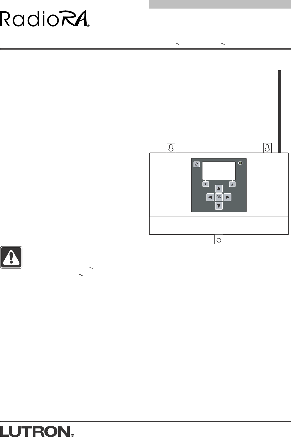
Overview
The System Bridging Timeclock (SBT) bridges two
RadioRA systems, providing a total of 64 Zone Controls
and 24 Master Controls. The SBT also provides an
RS-232 interface, contact closure inputs, and an astro-
nomic time clock.
Each SBT covers approximately 2500 square ft.
(232 m2) of living space.
Up to 3 RF Signal Repeaters may be used with the SBT
for each system to extend the communications range.
Important Notes
Codes: Install in accordance with all local and
national electrical codes.
Power: Use only the adapter provided by Lutron with
the SBT.
Caution - Using an adapter not rated for
the following specifications could damage
the SBT and possibly overheat the adapter.
• Input: 120/127 V 50/60Hz
• Output: 18 V / 0.3 A Class 2
Environment: Ambient operating temperature:
0-40°C, 32-104°F, 0-90% humidity, non-condensing.
Indoor use only.
Cleaning: To clean, wipe with a clean damp cloth.
DO NOT use any chemical solutions. Do not paint
the SBT.
Mounting: DO NOT ground the SBT. DO NOT
mount the SBT in a metal enclosure.
RF Device Placement: Master Controls and Zone
Controls that are to be controlled by the SBT must
be located within 30 ft. (9 m) of the SBT or an RF
Signal Repeater.
Setup: The SBT will not function until it is addressed
and programmed. See the System Bridging
Timeclock Setup and Programming Guide.
RA-SBT
RB-SBT
4. Configure the SBT. Use the SBT display to set
configuration.
5. Connect Serial Link (if applicable). Connect a
standard DB9 male connector to the RS-232 con-
nector on the SBT for communications with other
equipment.
6. Connect external input closures (optional). The
SBT accepts three low-voltage dry contact clo-
sures. Connect wiring for closures to input terminal
block if desired (see Wiring Diagram—page 3).
When using the input closures:
Verify compatibility of external devices. The input
closures are intended for use with devices that
provide outputs in the form of dry contact closure
outputs. The input closures may be used with
ground-referenced, solid-state outputs if the out-
puts have an on-state saturation voltage of less
than 2 V and an off-state leakage of less than
50 µA. Dry contact or solid-state outputs must be
capable of switching 18 V at 10 mA. The outputs
must stay in the closed or open states for at least
40 msec in order to be recognized by the SBT. If
there is any question as to whether the contact
closure device is compatible with these specifica-
tions, contact the manufacturer of that device.
2
PRELIMINARY—NOT FOR RELEASE
Installation
1. Find a suitable location for the SBT. Place the
SBT in a convenient and accessible location. See
RF Coverage Diagrams on page 5.
2. Mount the SBT. Mount SBT to wall using the
appropriate mounting hardware provided (see
Mounting Diagram). Orient the processor’s anten-
na for optimal performance. For most installations,
the antenna should be oriented vertically. Note:
DO NOT ground the SBT. DO NOT mount the SBT
in a metal enclosure.
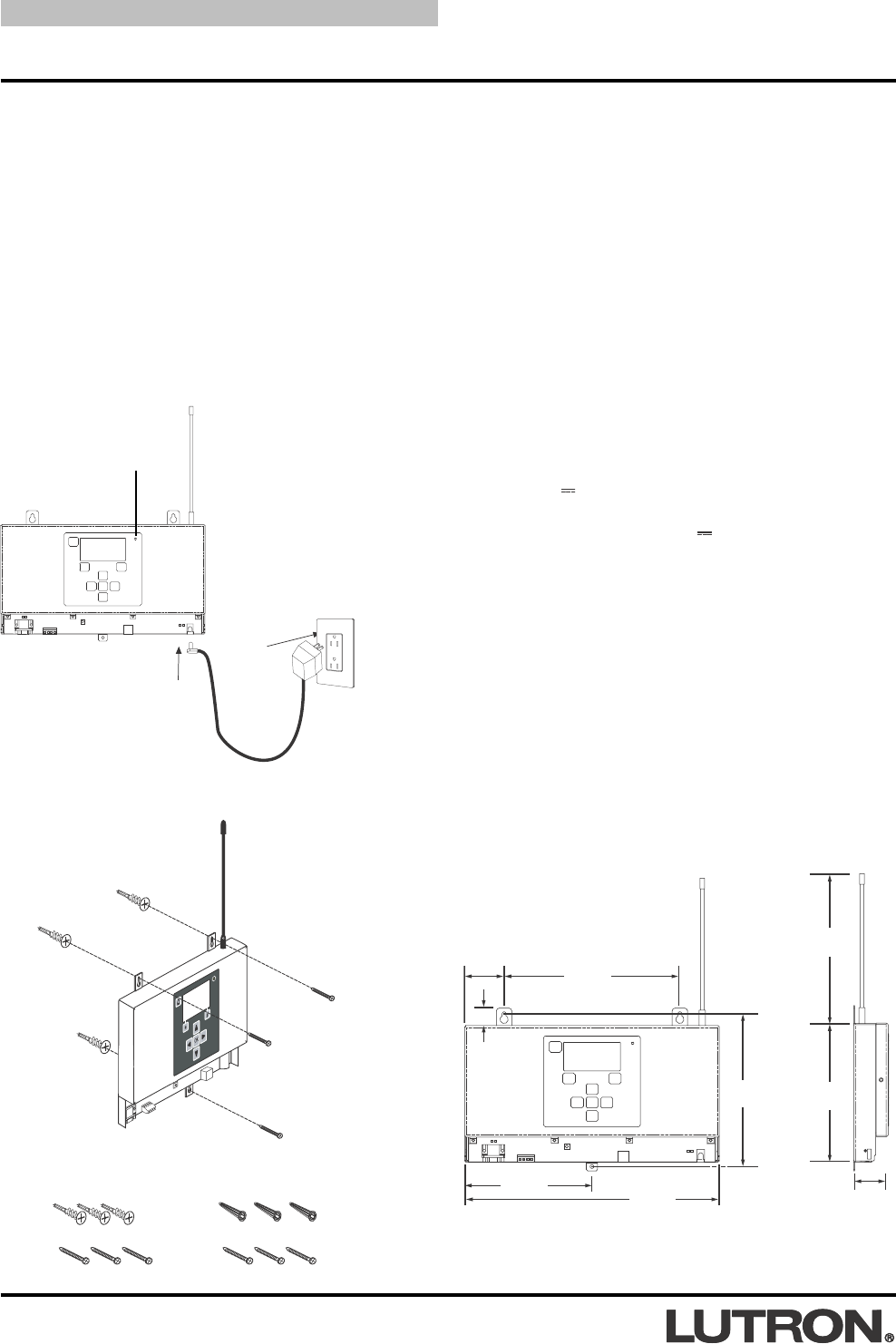
3. Apply power to the SBT.
Verify LED lights
when powered
Plug in power
cord and
adapter
11.54"
(293mm)
8"
(203mm)
1.25"
(32mm)
6.16"
(157mm)
6.7"
(170mm)
0.70"
(18mm)
Front View
(Port Cover removed)
Side View
5.77"
(147mm)
1.77"
(45mm)
Dimensions
Mounting Screw
Mounting Screw
Optional Mounting Screw
Mounting Diagram
Included:
Drywall Anchors (3)
Mounting Screws (3)
Masonry Anchors (3)
Mounting Screws (3)
Wall Anchors
7"
(178mm)
3
PRELIMINARY—NOT FOR RELEASE
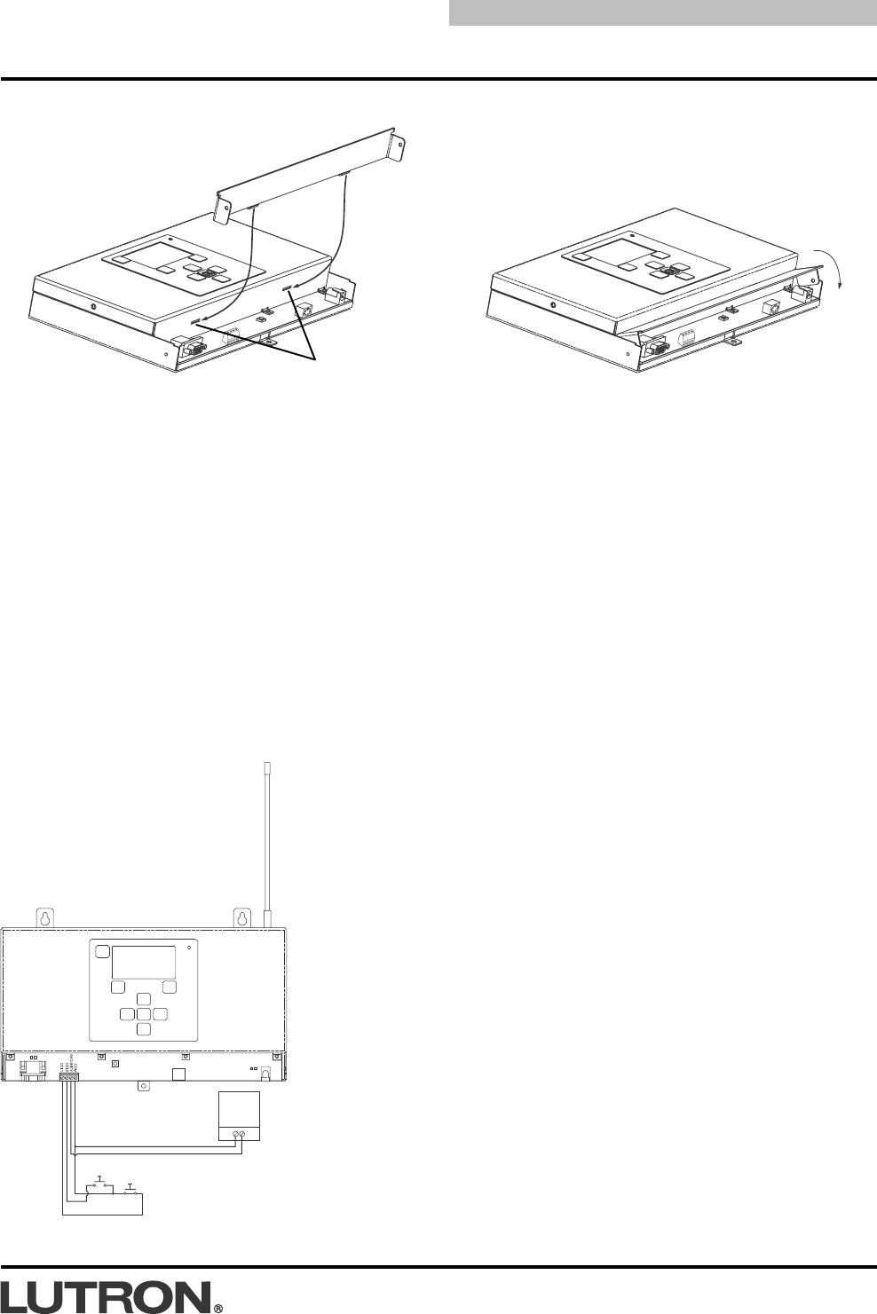
Contact Closure Input Wiring Diagram
SBT
Port Cover Installation
The Port Cover can be removed for access to the Reset Button and Diagnostic LEDs. The cover is removed by
gently pulling up on the front edge to disengage the snaps. Replace the cover by inserting the two tabs on the
back of the cover into the slots on the SBT. Gently press down on the front edge to engage the snaps.
Slots
Tab
Tab
Press
Down
Input 1
Input 2
Security
Input
4
PRELIMINARY—NOT FOR RELEASE
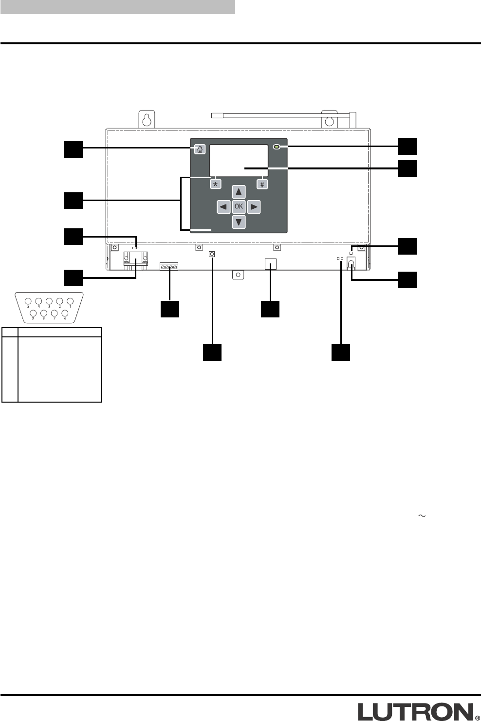
Operation
Home Key
Menu
Navigation
Keys
Display Power
LED
Power In LED
Keyboard Port
Reset Button
RS-232 Link
Activity LEDs
1. Home Key: Returns the user to the Home Screen.
2. Menu Navigation Keys: Used to navigate the various
menus and screens for the processor.
3. RS-232 Link Activity LEDs: The LEDs will illuminate
when there are any RS-232 signals being transmitted
(TX LED) or received (RX LED) on that link.
4. RS-232 Port: Standard 9-Pin male connector for con-
necting to an external control system (A/V system,
HVAC, etc.).
5. Contact Closure Inputs: Used for control by external
systems, such as A/V, Security, etc..
6. Reset Button: Used to reset the SBT.
7. Keyboard Port: Allows a computer keyboard to be con-
nected to the SBT for ease of programming and naviga-
tion. Standard PS/2 keyboard connector.
LCD Display
8. RF Activity LEDs: The LEDs will illuminate when there
are any RF signals being transmitted (TX LED) or
received (RX LED).
9. Power Input Jack: Input jack for the 18 V adapter.
Center pin is positive.
10. Power In LED: This LED illuminates when power from
the adapter is present at the Power Input Jack.
11. LCD Display: Displays programming and diagnostic
information. The LCD Display will shut off after 60 min-
utes of inactivity. To restore the display, simply press
any key.
12. Display Power LED: This LED will illuminate when the
LCD Display has power.
3
1
2
RS-232 Port 4
Contact
Closure Inputs
5
6
7
10
11
12
Power Input
Jack
9
PIN
1
2
3
4
5
6
7
8
9
Name Description
DCD Data Carrier Detect
TXD Transmit Data
RXD Receive Data
DSR Data Set Ready
GND Ground
DTR Data Terminal Ready
CTS Clear To Send
RTS Request To Send
RI Ring Indicate
RF Activity
LEDs
8
5
PRELIMINARY—NOT FOR RELEASE
#
#
*
Start
Start
P/N 292
-
153
P/N 292153
Tabletop Master
Control
Dimmer
30 ft. (9 m) maximum
SBT
Wall-mounted
Master Control
*
Sta
Sta
*
1
1
2
2
3
3
4
4
Dimmer
30 ft. (9 m) maximum
SBT
Wall-mounted Master Control
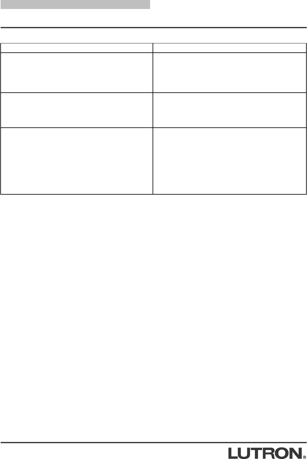
RF Signal Repeater
30 ft. (9 m) maximum
60 ft. (18 m) maxi-
mum between the
SBT and Repeaters,
or between Repeaters
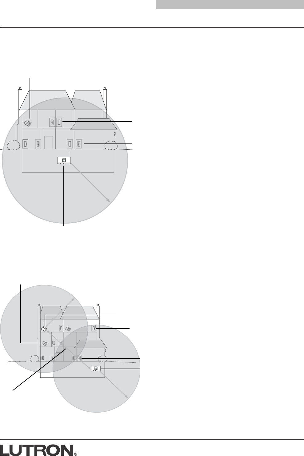
RF Coverage Diagrams
System Communication Notes
• Zone Controls and Master Controls
must be located within 30 ft. (9 m) of an
RF Signal Repeater or an SBT.
• RF Signal Repeater must be located
within 60 ft. (18 m) of an SBT or another
RF Signal Repeater.
• Multiple repeaters may be necessary to
provide adequate coverage. Up to 3
repeaters per system may be used with
the SBT.
• Zone Controls cannot be controlled by
the system and Master Controls do not
function until they are addressed and
programmed. Use the SBT Setup
Menus to address system devices.
Home A: 2500 sq. ft. (232 m2) or less - all devices within
30 ft. (9 m) of SBT
Home B: 2500 sq. ft. (232 m2) or greater - some RF devices more than 30 ft. (9 m) from SBT
Tabletop
Master
Control
6
PRELIMINARY—NOT FOR RELEASE
Troubleshooting Guide
Symptom Cause and Action
LCD is shut off.
• Press any key to restore the LCD.
No power available to SBT.
• Make sure adapter is plugged in.
• Faulty adapter.
• Check to make sure circuit breaker is not tripped or OFF.
No power available to unit.
• Make sure adapter is plugged in.
• Faulty adapter.
SBT not within 30 ft. (9 m) of controls.
• Place SBT within 30 ft. (9 m) of RF controls.
SBT not within 30 ft. (9 m) of controls.
• Place SBT within 30 ft. (9 m) of RF controls.
No power to Control
• Check circuit breaker.
• Check FASSTM on Dimmers/Switches and their Accessory
Controls.
• Replace batteries in battery-powered controls.
Controls not addressed.
• Address controls using the SBT Setup Menus.
LCD Display is blank
Controls not communicating with SBT
SBT functions intermittently

7
PRELIMINARY—NOT FOR RELEASE
Notes:

PRELIMINARY—NOT FOR RELEASE
Lutron Electronics Co., Inc.
7200 Suter Road
Coopersburg, PA 18036-1299
Made and printed in the U.S.A. 8/03 P/N 044-xxx Rev. A
LIMITED WARRANTY
Lutron will, at its option, repair or replace any unit that is defective in materials or manufac-
ture within two years after purchase. For warranty service, return unit to place of purchase or
mail to Lutron at 7200 Suter Rd., Coopersburg, PA 18036-1299, postage pre-paid. Telephone
the Lutron Technical Support Center toll free at 800-523-9466. After the two year period, a
pro-rated warranty applies to this product until eight years after the purchase. For more infor-
mation regarding this warranty contact your Lutron representative.
THIS WARRANTY IS IN LIEU OF ALL OTHER EXPRESS WARRANTIES, AND THE
IMPLIED WARRANTY OF MERCHANTABILITY IS LIMITED TO TWO YEARS FROM PUR-
CHASE. THIS WARRANTY DOES NOT COVER THE COST OF INSTALLATION,
REMOVAL OR REINSTALLATION, OR DAMAGE RESULTING FROM MISUSE, ABUSE,
OR IMPROPER OR INCORRECT REPAIR, OR DAMAGE FROM IMPROPER WIRING OR
INSTALLATION. THIS WARRANTY DOES NOT COVER INCIDENTAL OR CONSEQUEN-
TIAL DAMAGES. LUTRON’S LIABILITY ON ANY CLAIM FOR DAMAGES ARISING OUT
OF OR IN CONNECTION WITH THE MANUFACTURE, SALE, INSTALLATION, DELIVERY,
OR USE OF THE UNIT SHALL NEVER EXCEED THE PURCHASE PRICE OF THE UNIT.
This warranty gives you specific legal rights, and you may also have other rights which vary
from state to state. Some states do not allow limitations on how long an implied warranty lasts,
so the above limitation may not apply to you. Some states do not allow the exclusion or limi-
tation of incidental or consequential damages, so the above limitation or exclusion may not
apply to you.
This product may be covered by one or more of the following U.S. patents: 4,835,343;
4,954,768; 5,248,919; 5,399,940; 5,637,930; 5,736,965; 5,798,581; 5,838,226; 5,848,054;
5,905,442; 5,982,103 and corresponding foreign patents. U.S. and foreign patents pending.
Lutron, RadioRA, and the RadioRA logo are registered trademarks, and FASS is a trademark
of Lutron Electronics Co., Inc.
© 2003 Lutron Electronics Co., Inc.
Technical and Sales Assistance
If you need assistance, call the toll-free Lutron
Technical Support Center. Please provide exact
model number when calling.
(800) 523-9466 (U.S.A., Canada and the Caribbean)
Other countries call:
Tel: (610) 282-3800
Fax: (610) 282-3090
Visit our Web site at www.lutron.com
FCC Information
Note: This equipment has been tested and found to comply with the limits for a Class B digi-
tal device, pursuant to Part 15 of the FCC rules. These limits are designed to provide rea-
sonable protection against harmful interference in a residential installation. This equipment
generates, uses and can radiate radio frequency energy and, if not installed in accordance
with the instructions, may cause harmful interference to radio communications. However,
there is no guarantee that interference will not occur in a particular installation. If this equip-
ment does cause harmful interference to radio or television reception, which can be deter-
mined by turning the equipment off and on, the user is encouraged to try to correct the inter-
ference by one or more of the following measures:
• Reorient or relocate the receiving antenna.
• Increase the seperation between the equipment and receiver.
• Connect the equipment into an outlet on a circuit different from that to which the
receiver is connected.
• Consult the dealer or an experienced radio/TV technician for help.
Caution: Changes or modifications not expressly approved by Lutron Electronics Co. could
void the user’s authority to operate this equipment.