Lutron Electronics 0034 Lighting Control Transciever User Manual
Lutron Electronics Company Inc Lighting Control Transciever
Contents
- 1. Users Manual
- 2. User Manual
User Manual
R
Job Name:
Job Number:
Model Numbers:
Page
SPECIFICATION SUBMITTAL
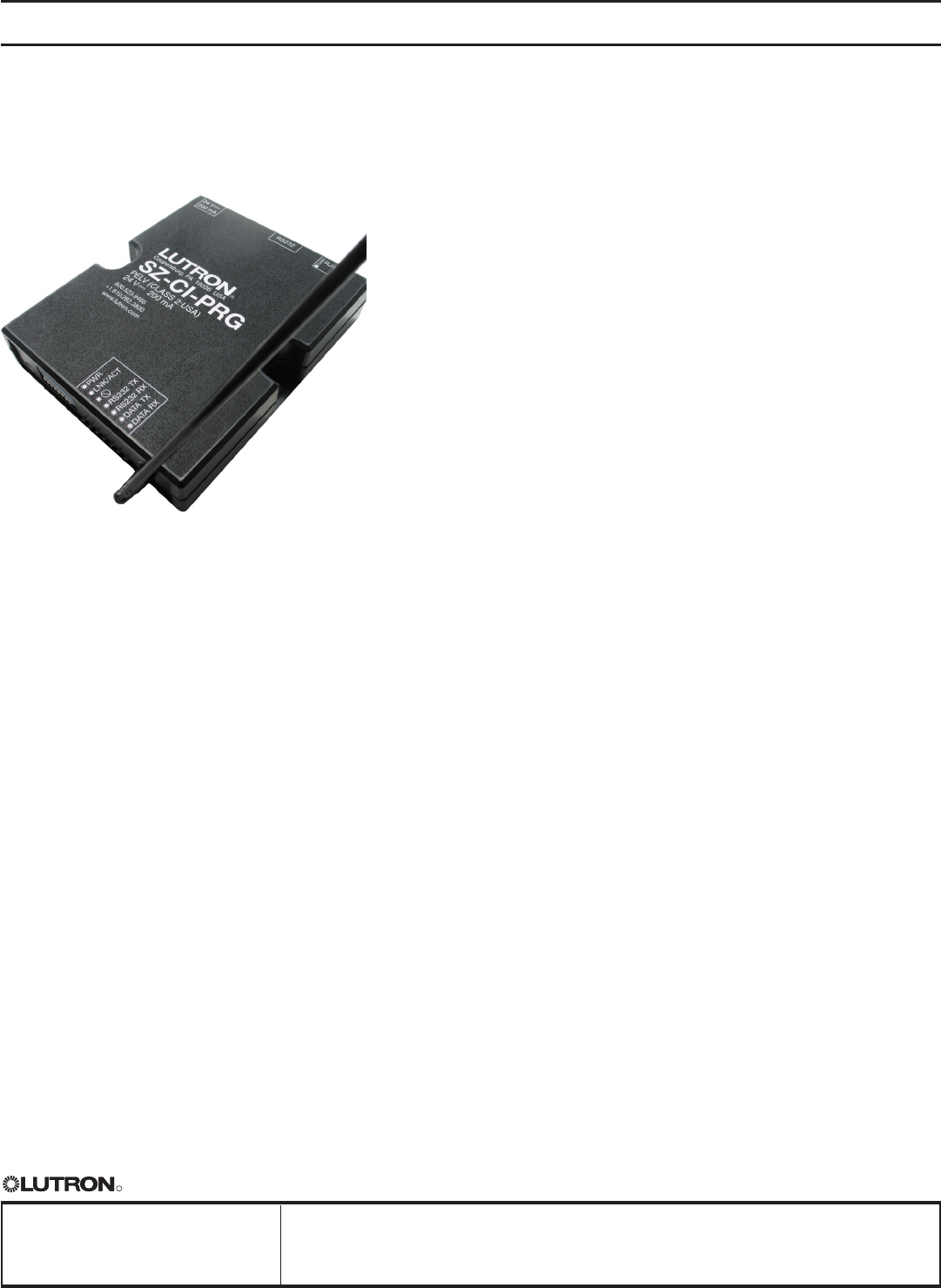
SZ-CI-PRG Programming Control Interface
Description
The Stanza system is an easy-to-install and easy-to-use lighting
control system designed especially for hotel guest rooms and
similar applications. The system consists of wallbox dimmers,
wallbox switches, line-voltage wallbox keypads, low-voltage
interfaces, and lamp socket dimmer/switches. All of these
devices communicate via radio frequency (RF) within each
individual guest room.
The Stanza programming control interface allows setup,
commissioning, and modification of Stanza systems, and can
also be used to integrate with a PC or other digital equipment
that supports TCP/IP over 10/100 BaseT Ethernet or RS232
connections.
Features
• Integrates a Stanza guest room lighting control system with a
PC or other digital equipment that supports RS232 or Ethernet
TCP/IP communication.
• Provides a basic serial string command set that allows a PC to
monitor and control lighting.
• Enables use of a PC to set up and commission Stanza systems.
• At least one SZ-CI-PRG is required per job for commissioning
or system modification. Programmed and commissioned
systems do not require a SZ-CI-PRG to be present for
continued operation.
• Wireless connection allows easy mounting near integration
device.
sz-ci-prg-1 06.06.08
Wireless Control InterfacesSZ-CI-PRG
StanzaTM
1
FCC Information
Note: This equipment has been tested and found to comply with the limits for
a Class B digital device, pursuant to Part 15 of the FCC rules. These limits are
designed to provide reasonable protection against harmful interference in a residential
installation. This equipment generates, uses and can radiate radio frequency
energy and, if not installed and used in accordance with the instructions,
may cause harmful interference to radio or television reception. However,
there is no guarantee that interference will not occur in a particular installation.
If this equipment does cause harmful interference to radio or television reception,
which can be determined by turning the equipment off and on, the user is
encouraged to try to correct the interference by one or more of the following
measures:
• Reorient or relocate the receiving antenna.
• Increase the seperation between the equipment and receiver.
• Connect the equipment into an outlet on a circuit different from that to
which the receiver is connected.
• Consult the dealer or an experienced radio/TV technician for help.
Caution: Changes or modifications not expressly approved by Lutron
Electronics Co. could void the user’s authority to operate this equipment.
Operation is subject to the following: (1) This device may not cause harmful
interference, and (2) this device must accept any interference received,
including interference that may cause undesired operation.
R
Job Name:
Job Number:
Model Numbers:
Page
SPECIFICATION SUBMITTAL
Standards:
• FCC approved. Complies with the limits for a Class
B digital device, pursuant to Part 15 of the FCC
rules
Power:
• Low-voltage PELV (Class 2: USA).
• Operating Voltage: 15 - 24 V , 500 mA maximum.
• AC adapter included (requires 120 V outlet).
Integration:
• Provides one 10/100 Base T (autosensing) Auto-
MDIX jack for connecting to an Ethernet network
using TCP/IP.
• Provides one DB9 RS232 jack for connecting to a
serial device.
• Baud rates supported over RS232: 9600, 38400,
115200.
Key Design Features:
• LED status indicators provide device diagnostics
• Power failure memory: if power is interrupted, when
the power is restored, device will retain all settings
that were in place prior to the interruption
System Communication and Capacity:
• Programming control interface communicates with
other Stanza system components through radio
frequency (RF) at 434 MHz
• Multiple RF channels and thousands of system
addresses prevent interference between systems
• When used only for commissioning and
programming, programming control interface does
not count toward the single-system maximum of 31
Stanza devices
Specifications
sz-ci-prg-2 06.06.08
Wireless Control InterfacesSZ-CI-PRG
StanzaTM
Environment:
• Ambient operating temperature: 32 - 104 °F
(0 - 40 °C)
• Maximum 90% non-condensing relative humidity
• Indoor use only
• Cannot be mounted in a metal enclosure (interferes
with RF reception).
Warranty:
• 1-year limited warranty
• 2-year full parts and labor warranty, with 8-year pro-
rated parts replacement on commissioned systems
Color/Finish Codes:
• Black only
2
R
Job Name:
Job Number:
Model Numbers:
Page
SPECIFICATION SUBMITTAL
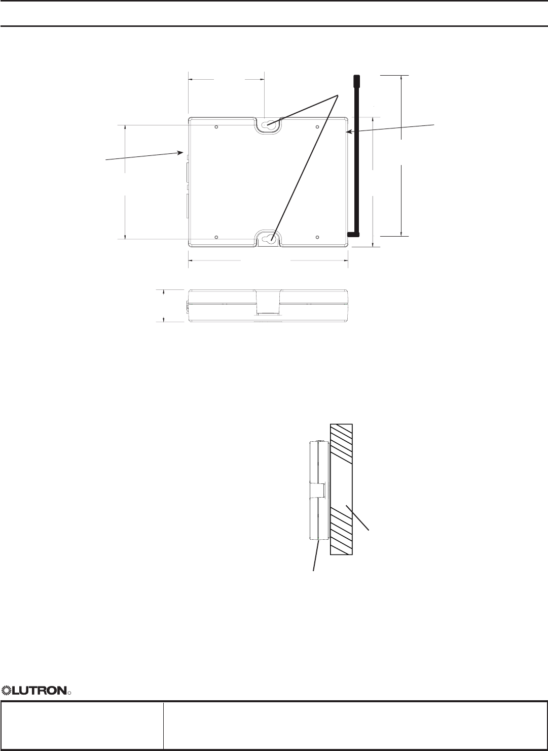
2.50
(63.5)
3.75
(95.3)
4.26
(108.2)
5.26
(133.6)
1.06
(26.9)
Mounting holes
Mounting
1. Mount the control interface directly on a surface, as
shown in the Mounting Diagram, using screws (not
included). When mounting, provide sufficient space
for the antenna and connecting cables. The unit can
be mounted in any orientation.
The unit cannot be mounted in a full metal
enclosure. The antenna is not removable or remotely
mountable.
Mount in an accessible location for convenient
access to addressing switches, LEDs, and terminal
blocks.
2. Connect wiring as shown in the Wiring Diagram
(next page).
5.26
4.263.75
2.50
1.06
Control Interface
Surface
Mounting Diagram
Dimensions
Dimensions are in inches (mm)
6.0
(152.4)
sz-ci-prg-3 06.06.08
Wireless Control InterfacesSZ-CI-PRG
StanzaTM
Terminal
blocks on this
side
LEDs and
addressing
switches on this
side
3
R
Job Name:
Job Number:
Model Numbers:
Page
SPECIFICATION SUBMITTAL
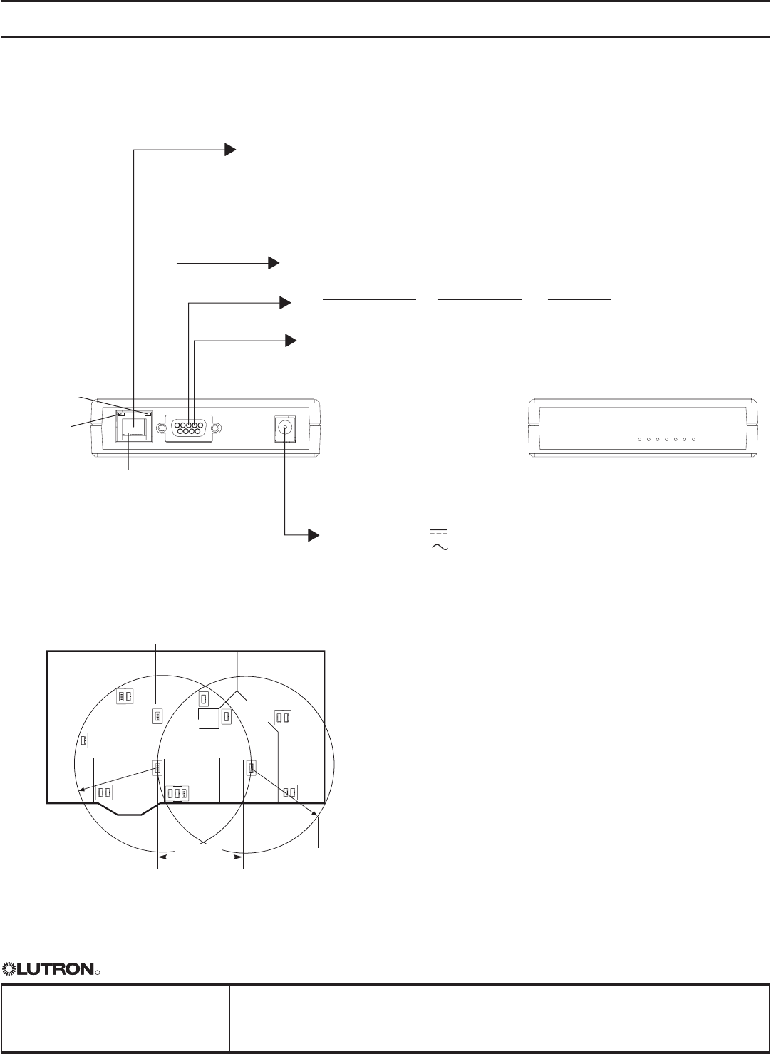
Wiring Diagram
1234567
RJ45 jack:
Ethernet link
(to PC or A/V
equipment)
Ethernet
link/
activity
Ethernet speed
On = 100 Mbit/sec
Off = 10 Mbit/sec
CAT5 Cable:
maximum 328 ft.
(100 m)
To PC or AV equipment. For Ethernet link, use CAT5 cable provided to connect to
auxiliary equipment. The Ethernet link LED will light continuously when link is present
and will flash when there is link activity. Additional Ethernet network equipment and
cables provided by others.
PELV (Class 2: USA) Power in
500 mA 12 - 24 V
(powered by 120 V transformer, included).
RS232 Cable:
maximum 50 ft.
(15 m)
COM
TxD
RxD
To PC or AV equipment: Use the 9-pin cable
provided, or follow the chart below.
RS232 Pin Connect Wiring
Typical PC or Pin on
RS232 Interface A/V equipment 9-pin cable
Common Com 5
Receive TxD 3
Transmit RxD 2
LED 1: Power
LED 2: Ethernet link
LED 3: Unused
LED 4: RS232 link TX
LED 5: RS232 link RX
LED 6: Unused
LED 7: Unused
System Communication Notes
• Stanza lighting controls, keypads, and interfaces
must be located within 20 feet (6 m) of a Stanza
device configured as a repeater. Multiple devices
configured as repeaters may be necessary to
provide adequate coverage.
• A total of 3 devices maximum can be configured
as repeaters.
• Devices configured as repeaters must be within
20 feet (6 m) of another device configured as a
repeater.
• Stanza lighting controls cannot be controlled
wirelessly and Stanza keypads will not function
until they are addressed and programmed.
System Limits
• 31 devices maximum
• 20 feet (6 m) from device to repeater devices
• Dimmers, keypads, or contact closure devices
can be repeaters
System Overview
20 ft. (6 m) max.
from repeater device
Dimmer
Keypad
20 ft. (6 m) max.
from repeater device
20 ft. (6 m)
maximum
sz-ci-prg-4 06.06.08
Wireless Control InterfacesSZ-CI-PRG
StanzaTM
Diagnostic
LEDs
4