Lutron Electronics 0038 Tabletop Radio Frequency Key Pad Control User Manual Aurora Repl Dimmer Inst qxp
Lutron Electronics Company Inc Tabletop Radio Frequency Key Pad Control Aurora Repl Dimmer Inst qxp
Usres Manual

Lutron Electronics Co., Inc.
7200 Suter Road
Coopersburg, PA 18036-1299, U.S.A.
Made and printed in the U.S.A. 2/06 P/N 044-108 Rev. A
FCC Information
Note: This equipment has been tested and found to comply with the limits for
a Class B digital device, pursuant to Part 15 of the FCC rules. These limits are
designed to provide reasonable protection against harmful interference in a res-
idential installation. This equipment generates, uses and can radiate radio fre-
quency energy and, if not installed and used in accordance with the instruc-
tions, may cause harmful interference to radio or television reception. However,
there is no guarantee that interference will not occur in a particular installation.
If this equipment does cause harmful interference to radio or television recep-
tion, which can be determined by turning the equipment off and on, the user is
encouraged to try to correct the interference by one or more of the following
measures:
• Reorient or relocate the receiving antenna.
• Increase the seperation between the equipment and receiver.
• Connect the equipment into an outlet on a circuit different from that to
which the receiver is connected.
• Consult the dealer or an experienced radio/TV technician for help.
Caution: Changes or modifications not expressly approved by Lutron
Electronics Co. could void the user’s authority to operate this equipment.
Operation is subject to the following: (1) This device may not cause harmful
interference, and (2) this device must accept any interference received,
including interference that may cause undesired operation.
Limited Warranty
(Valid only in the U.S., Canada, Puerto Rico, and the Caribbean.)
Lutron will, at its option, repair or replace any unit that is defective in materials
or manufacture within one year after purchase. For warranty service, return unit
to place of purchase or mail to Lutron at 7200 Suter Rd., Coopersburg, PA
18036-1299, postage pre-paid .
THIS WARRANTY IS IN LIEU OF ALL OTHER EXPRESS WARRANTIES,
AND THE IMPLIED WARRANTY OF MERCHANTABILITY IS LIMITED TO
ONE YEAR FROM PURCHASE. THIS WARRANTY DOES NOT COVER THE
COST OF INSTALLATION, REMOVAL OR REINSTALLATION, OR DAMAGE
RESULTING FROM MISUSE, ABUSE, OR IMPROPER OR INCORRECT
REPAIR, OR DAMAGE FROM IMPROPER WIRING OR INSTALLATION.
THIS WARRANTY DOES NOT COVER INOPERABILITY RESULTING FROM
INTERFERENCE, INCORRECT INSTALLATION, OR ENVIRONMENTAL
FACTORS. THIS WARRANTY DOES NOT COVER INCIDENTAL OR CONSE-
QUENTIAL DAMAGES. LUTRON’S LIABILITY ON ANY CLAIM FOR DAM-
AGES ARISING OUT OF OR IN CONNECTION WITH THE MANUFACTURE,
SALE, INSTALLATION, DELIVERY, OR USE OF THE UNIT SHALL NEVER
EXCEED THE PURCHASE PRICE OF THE UNIT.
This warranty gives you specific legal rights, and you may also have other rights
which vary from state to state. Some states do not allow limitations on how long
an implied warranty lasts, so the above limitation may not apply to you. Some
states do not allow the exclusion or limitation of incidental or consequential
damages, so the above limitation or exclusion may not apply to you.
These products may be covered under one or more of the following U.S.
patents: 4,835,343; 4,954,768; 5,248,919; 5,399,940; 5,637,930; 5,736,965;
5,798,581; 5,838,226; 5,848,054; 5,905,442; 5,982,103; 6,687,487; D353,798
and corresponding foreign patents. U.S. and foreign patents pending.
Lutron, Fassada, and the sunburst logo are registered trademarks and AuroRA
is a trademark of Lutron Electronics Co., Inc.
© 2006 Lutron Electronics Co., Inc.
Technical Assistance
If you have questions concerning the installation or opera-
tion of this product, call the Lutron Technical Support
Center. Please provide exact model number when calling.
+1.800.523.9466 (U.S.A., Canada, and the Caribbean)
Other countries call +1.610.282.3800
Fax +1.610.282.3090
Visit our web site at www.lutron.com
Important Notes
11.. Caution:: To avoid overheating and possible damage to
other equipment, do not use dimmers to control recep-
tacles, fluorescent lighting fixtures, motor-operated or
transformer-supplied appliances.
22..Use dimmers with 120V incandescent lighting fixtures
only. Do not use with low-voltage transformers.
33..Install in accordance with all national and local electrical
codes.
44..When there is no ground wire or a way to connect the
wallbox to ground within the wallbox then the NEC®
2002, Article 404-9 allows a dimmer without a ground-
ing connection to be installed as a replacement, as long
as a plastic, noncombustible wallplate is used. For this
type of installation, cap or remove the green ground
wire on the dimmer and use an appropriate wallplate
such as Lutron’s Fassada®series wallplates.
55..Do not paint dimmers or wallplates.
66..The total wattage of all light bulbs controlled by each
dimmer must be between 50 and 600 watts.
77..Dimmers work with most incandescent light bulbs.
Dimmers may not work with dioded light bulbs (Sylvania
CAPSYLITE DESIGNER 16TM or Philips PAR-16TM).
88..Operate system in temperatures between 0 °C
(32 °F) and 40 °C (104 °F).
99..Dimmer may feel warm to the touch during normal
operation.
1100..Recommended wallbox depth is 2 1/2" minimum.
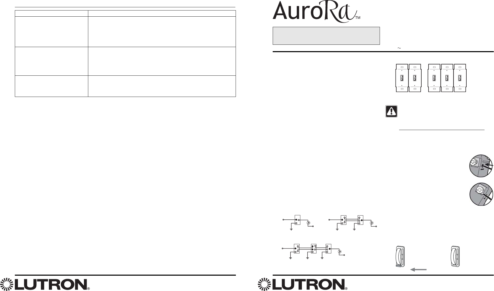
1111..single-pole circuit three-way circuit
four-way circuit
1122..When combining dimmers in the same wallbox, the
dimmer’s load capacity must be reduced.
1133..Wire Preparation
Trim or strip wallbox wires to the length
indicated by the strip gauge on the back
of the dimmer.
Push-in: Insert wires fully. Use #14 AWG
solid copper wire only. For aluminum
wire, consult an electrician. DO NOT use
stranded or twisted wire.
Screw Terminals: Tighten securely. Screw
terminals are for use with solid copper
wire only. For aluminum wire, consult an
electrician. DO NOT use stranded or twisted wire.
1144..Service Switch
Pull service switch out to open position to replace light
bulbs. Push service switch in after new bulb is
installed.
Installation Instructions for
Replacement Dimmer
Read all instructions completely before installation.
Incandescent / 120 V Halogen
Dimmer
AR-6D
120 V 50/60 Hz 600 W
Possible Cause
• Front Accessible Service Switch (FASSTM) on Dimmer is pulled out to the
OFF position.
• Light bulb(s) burned out.
• Breaker is OFF or tripped.
• Dimmer is out of RF range.
• Dimmer not activated to system.
• Keypad not activated to system.
• Miswire–check wiring with 3-way or 4-way diagram on page 1.
• Dimmer is in 4-way location–move Dimmer to 3-way location.
Troubleshooting
Symptom
Light does not turn ON.
Dimmer does not respond to
Keypad button press.
Dimmer does not switch from 3-way
location.
Follow the load capacities in table below for multi-
ganged dimmers.
single
gang
600W
max
double
gang
500W
max
triple
gang
400W
max
double gang triple gang
service switch
open
service switch
closed
Hot
120V
60Hz
Dimmer
Ground Ground
Neutral
Light
3-way
Switch
Hot
120V
60Hz
Dimmer
Ground
Neutral
Light
Hot
120V
60Hz
Dimmer 3-way
Switch
Ground Ground Ground
Neutral
Light
4-way
Switch
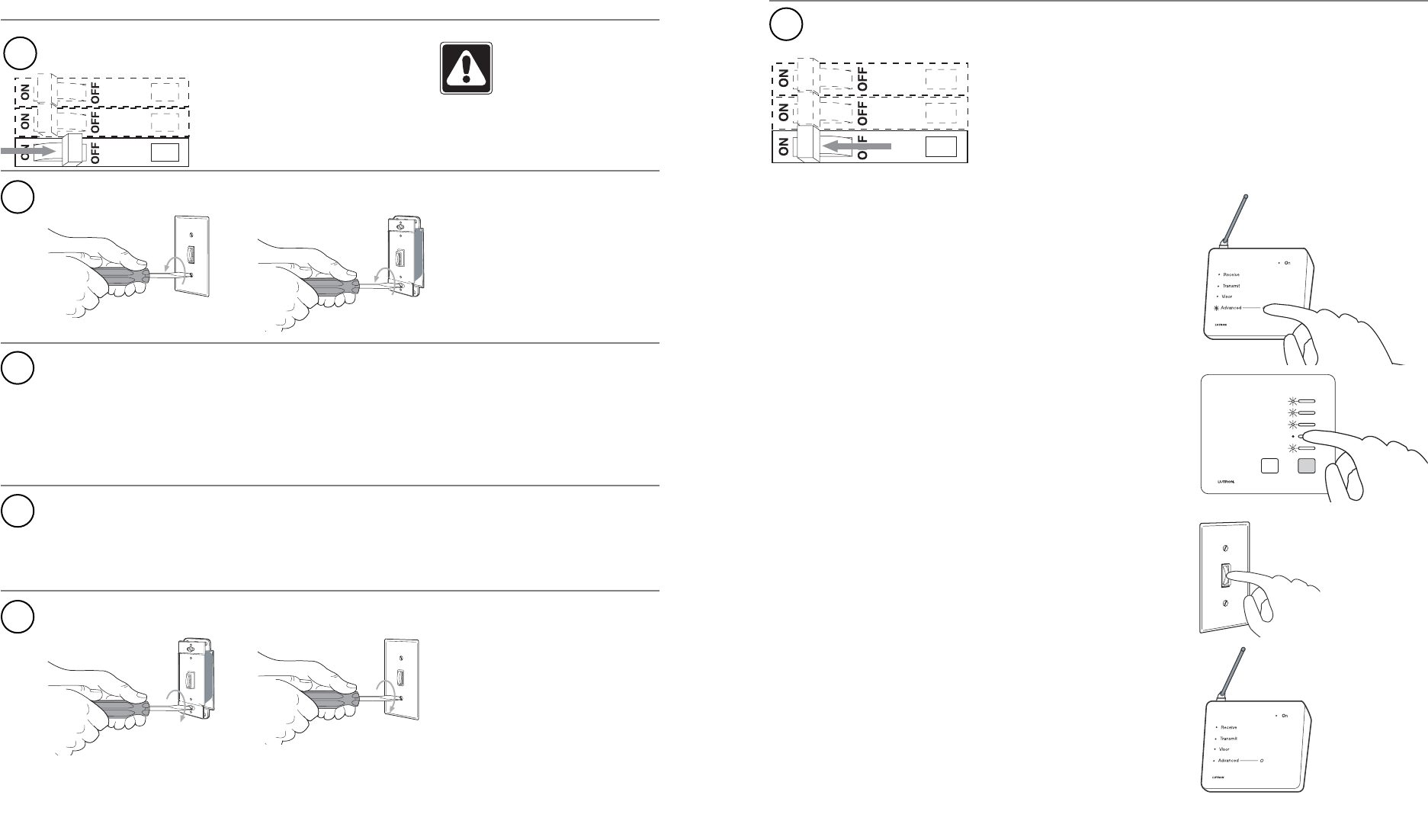
1

Installing a Replacement Dimmer
2 3
Install replacement dimmer
A. Note which wire(s) are connected to each terminal. The
replacement dimmer will be installed identically.
B. Disconnect the wires from the dimmer.
4
Uninstall existing dimmer
WARNING: Power must
be turned off for your
safety.
1
2
3
Turn power off at circuit breaker or remove fuse
Turn power on at circuit breaker or replace fuse
Connect the wires to the terminals on the replacement dimmer
in the same configuration they were connected to the old dim-
mer.
6
Mount dimmer and replace wallplate
5
1. Enter Device Replacement: Press and hold the Advanced but-
ton (on the Central Antenna) for approximately 3 seconds. The
Advanced LED will be on solid during the press until the hold is
detected. When the hold is detected, the Advanced LED will
flash slowly.
2. Dimmers that are already in the System will flash the lights con-
nected to each. The Master Control will have the following LED
feedback: LED flashing corresponds to a Dimmer present and
LED off corresponds to a Dimmer not present. Press and
Release the Master Control button that corresponds to the
Dimmer not present.
3. Press and hold the button on the Replacement Dimmer for
approximately three seconds. Upon successful replacement,
the Dimmer will start flashing its lights and the selected Keypad
button will flash its LED.
4. Exit Device Replacement: Press and hold the Advanced button for
approximately 3 seconds. The Advanced LED will turn off and the
Dimmer will stop flashing its lights.
5. Dimmer now works in System.
Remove wallplate and existing dimmer. Do not disconnect
wires. Activating the Replacement Dimmer in your system