Lutron Electronics 0040 Lighting Control Transceiver User Manual 044 004b RadioRA IR interface
Lutron Electronics Company Inc Lighting Control Transceiver 044 004b RadioRA IR interface
Users Manual

RAMC-MFE, RBMC-MFE
Setup and Installation Guide For a RadioRA®
Multi-Function Entry Master Control
®
A Comprehensive Step-by-Step Guide for Installing, Programming,
and Operating the Lutron RadioRA® Multi-Function Entry Master Control
Note: Please leave this manual with homeowner.
Wireless Home Lighting Control
English
P/N 044-022
RadioRA
®
Setup Guide for the Entry Master Control
2
Notes on this Manual
The procedures to setup a RadioRA® Multi-Function Entry Master Control are contained in this manual. For more
information on programming the remainder of your RadioRA® System, or for advanced features, refer to the
original RadioRA® Setup Guide (P/N 044-001).
Consumer Information
Notice
This Visor Control System, consisting of a Multi-Function Entry Master Control and a Visor Control transmitter, must only be
used to operate visible means of barrier entry such as garage doors and motorized gates. Do not use this Multi-Function
Entry Master Control with any garage door opener that lacks the safety stop and reverse feature as required by federal
safety standards. (This includes any garage door opener model manufactured before April 1, 1982.) A garage door opener
which cannot detect an object, signaling the door to stop and reverse, does not meet current federal safety standards. Using
a garage door opener without these features increases risk of serious injury or death.
Warning
This RadioRA® system must not be used to control equipment, other than lighting, which is not visible from every master or
local control location. It also must not be used to control equipment which could create hazardous situations such as
entrapment if operated accidentally. Examples of equipment which must not be controlled by this RadioRA® system when
not visible from a Multi-Function Entry Master Control or local control location include (but are not limited to) motorized
gates, garage doors, industrial doors, and microwave ovens, heating pads, etc. It is the installer's responsibility to ensure
that the equipment, other than lighting, being controlled is visible from every master or local control location and that only
suitable equipment is connected to this RadioRA® system.
FCC Information
NOTE: This equipment has been tested and found to comply with the limits for a Class B digital device, pursuant to part 15 of the FCC rules. These limits are
designed to provide reasonable protection against harmful interference in a residential installation. This equipment generates, uses and can radiate radio
frequency energy and, if not installed and used in accordance with the instructions, may cause harmful interference to radio or television reception, which can
be determined by turning the equipment off and on, the user is encouraged to try to correct the interference by one or more of the following measures:
• Reorient or relocate the receiving antenna.
• Increase the separation between the equipment and receiver.
• Connect the equipment into an outlet on a circuit different from that to which the receiver is connected.
• Consult the dealer or an experienced radio/TV technician for help.
Caution: Changes or modifications not expressly approved by Lutron Electronics Co. could void the user's authority to operate this equipment.
Important Application Note
The Multi-Function Entry Master Control is a type of Master Control. The RadioRA® System can have a maximum
of 12 Master Controls.
Important Installation Notes
1. Install in accordance with all national and local electrical codes.
2. Do not paint the Multi-Function Entry Master Control.
3. Operate in ambient temperatures between 0°C (32°F) and 40°C (104°F).
4. Do not mount outside. Unit must not get wet.
5. Use only the AC adapter provided by Lutron with your Multi-Function Entry Master Control. Using an AC
adapter not rated at the following specifications could damage the control and possibly overheat the AC
adapter.
• Input: AC 120V 60Hz
• Output: AC 9V/500mA Class 2
6. The range and performance of the RadioRA® System is highly dependent on a variety of complex factors such
as:
• Distance between system components
• Geometry of the home
• Construction of walls separating system components
• Electrical equipment located near system components

RadioRA
®
Setup Guide for the Entry Master Control
3
Table of Contents
Section 1 - Overview
Overview
Multi-Function Entry Master Control .............................................................................................4
Application Examples
Activating a “Home” Lighting Scene ............................................................................................6
Controlling a Garage Door .............................................................................................................6
Interfacing to a Timeclock ..............................................................................................................7
Interfacing to a Security System ...................................................................................................7
Section 2 - Installation
Installing an Entry Master Control
Installation .......................................................................................................................................8
Section 3 - Start-Up
Activating an Entry Master Control
Activating Control ...........................................................................................................................10
Button Programming
Assigning a Column of Buttons as ROOMS or SCENES ............................................................11
Assigning Dimmers, Switches, or GRAFIK Eye® Control Units to Buttons ...............................12
Setting Light Levels/GRAFIK Eye® Scene Selection for Buttons ...............................................13
Configuring General CCIs as Maintained or Momentary............................................................. 14
Entry Master Control Learning a Visor Control ............................................................................ 16
Section 4 - Advanced Features
Advanced Programming
Programming the ALL ON Button ..................................................................................................18
Programming the ALL OFF Button ................................................................................................ 18
Copying Button Programming .......................................................................................................18
Erasing Button Programming ........................................................................................................18
Programming the FULL and FLASH Buttons ...............................................................................19
Deleting ALL Visor Control Transmitters from an Entry Master Control ...................................22
Section 5 - Troubleshooting
Troubleshooting Guide .................................................................................................................
24
Returning to Default Factory Settings
Entry Master Control .......................................................................................................................25
RadioRA
®
Setup Guide for the Entry Master Control
4
Section 1 - Overview
Overview
Multi-Function Entry Master Control
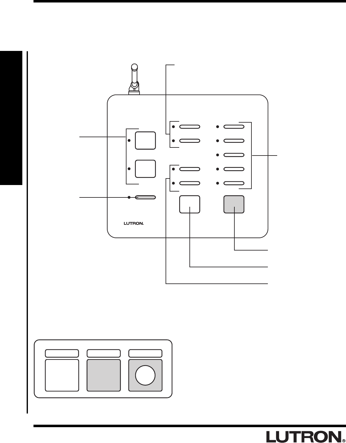
Visor Control Transmitter (sold separately)
• Mounts to a vehicle’s visor.
• Buttons provide a means for remotely activating buttons
on the Entry Master Control.
• Turn on an Entry Master Control SCENE
• Toggles an Entry Master Control ROOM
• SECURITY FULL and FLASH
• To enter, press and hold Visor Control button setup as
security button for 3 seconds.
• To exit, just press any button on the Visor Control.
Front View
ALL ON Button
Turns all lights ON.
CCI Buttons
Provide a means for programming the
general inputs. Also toggles the ROOM or
SCENE when pressed.
ALL OFF Button
Turns all lights OFF.
ROOM or SCENE
Buttons Toggle lights
ON and OFF. Works just
like ROOM/SCENE
buttons on a standard
RadioRA® Master
Control.
FULL and FLASH Buttons
Provide a means for
programming the security
input. Also provide
diagnostic capability for
FULL and FLASH.
CCO Buttons
Provide a contact
closure output for as
long as the button is
pressed.
LEARN Button
Used to enter LEARN
mode. LEARN mode is
used when the Multi-
Function Entry Master
Control is learning Visor
Control Transmitter
buttons.
SECURITY
CCI 2
CCI 1
FLASH
FULL
CCO 2
CCO 1
LEARN
RadioRA
®
Setup Guide for the Entry Master Control
5
Section 1 - Overview
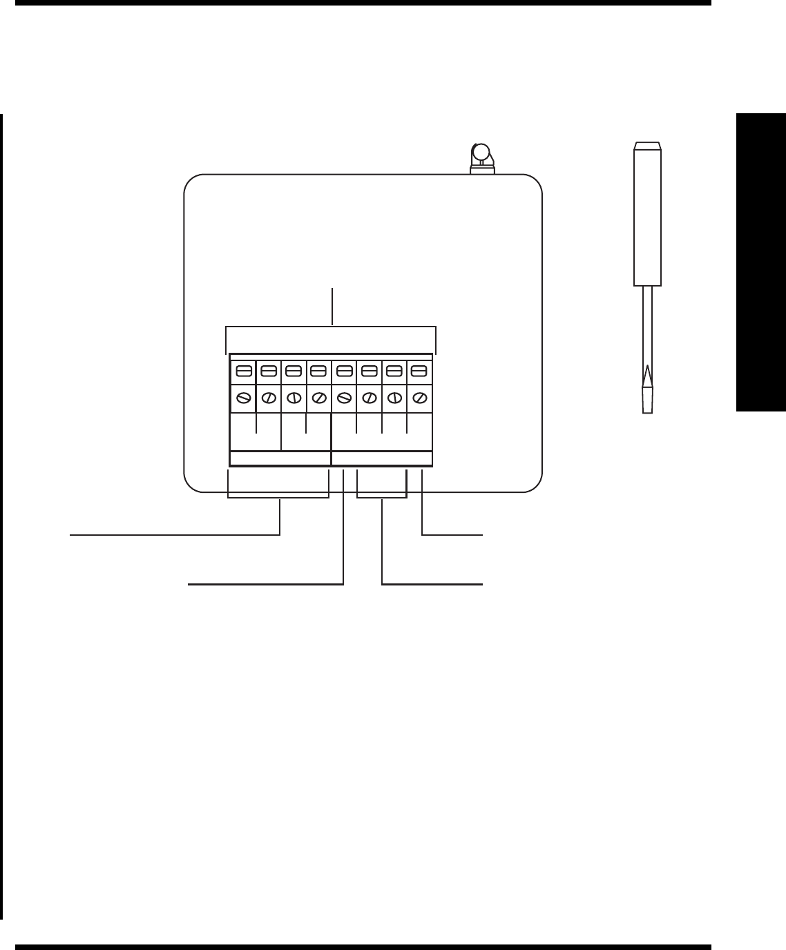
Rear View
Use included
screwdriver to
secure wires into
terminals.
Overview
OUTPUTS INPUTS
1212
CCO 1 CCO 2
COM
CCI 2
CCI 1
FLASH
FULL
Common
Common connection for all inputs.
General Inputs
Turns ON a ROOM or SCENE when
set as a momentary input; toggles a
ROOM or SCENE when set as a
maintained input.
FULL FLASH Security Input
Activates FULL and FLASH scenes
while a maintained input is present.
Outputs
Provide a momentary contact
closure output.
Terminal Block
Each terminal accepts
14-22 AWG, Class 2 wire.

RadioRA
®
Setup Guide for the Entry Master Control
6
Section 1 - Overview
Overview
Application Examples
Activating a “Home” Lighting Scene
Pressing the “Home” button on the Entry Master Control activates the “Home” lighting scene.
AWAY
NIGHT
HOME
MORNING
WELCOME
ALL ON ALL OFF
SECURITY
FLASH
FULL
CCO 2
CCO 1
LEARN
GARAGE 1
GARAGE 2
SUNRISE
SUNSET
HOME AWAY GARAGE 1
– OR –
Pressing the “Home” button
on the Visor Control
activates the same “Home”
lighting scene.
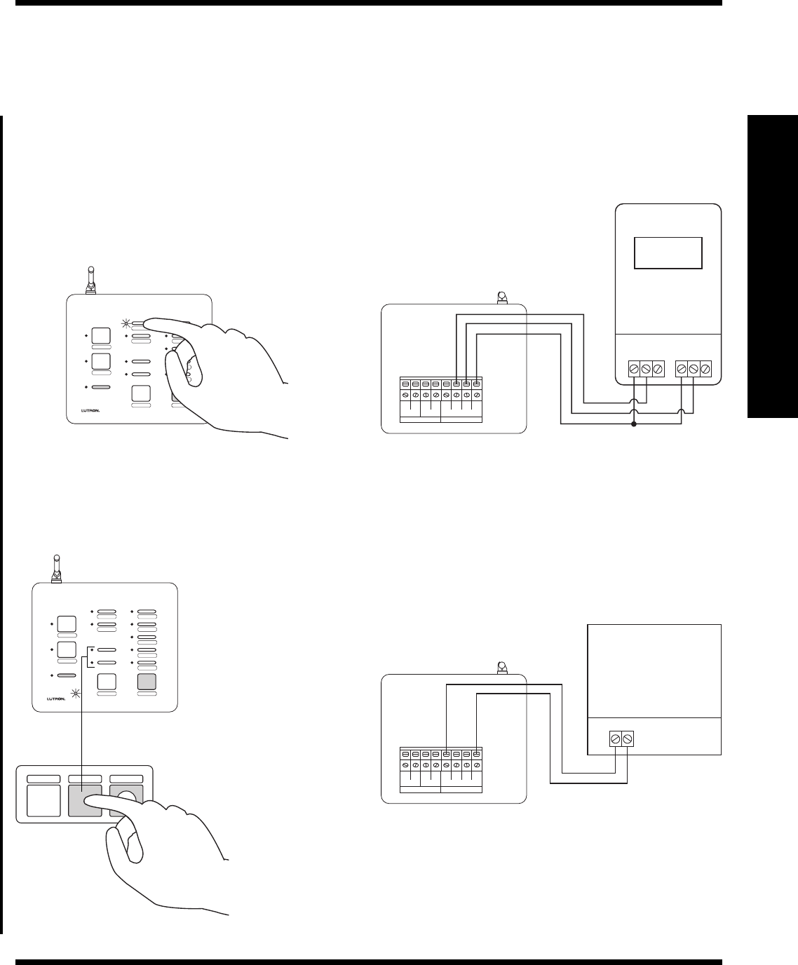
Controlling a Garage Door
Pressing the button labeled “Garage 1” closes the contact of CCO 1 to open or close the garage door.
AWAY
NIGHT
HOME
MORNING
WELCOME
ALL ON ALL OFF
SECURITY
FLASH
FULL
CCO 2
CCO 1
LEARN
GARAGE 1
GARAGE 2
SUNRISE
SUNSET
OUTPUTS INPUTS
1212
CCO 1 CCO 2
COM
CCI 2
CCI 1
FLASH
FULL
Garage Door Opener
HOME AWAY GARAGE 1
– OR –
Pressing the “Garage 1” button on
the Visor Control will also open or
close the garage door.
RadioRA
®
Setup Guide for the Entry Master Control
7
Section 1 - Overview
HOME SECURITY GARAGE 1
Overview
Interfacing to a Timeclock
The lighting scene “Sunset” on the Entry Master Control can be activated by either pressing the button labeled
“Sunset” or by an input closure on CCI 1.
AWAY
NIGHT
HOME
MORNING
WELCOME
ALL ON ALL OFF
SECURITY
FLASH
FULL
CCO 2
CCO 1
LEARN
GARAGE 1
GARAGE 2
SUNRISE
SUNSET
OUTPUTS INPUTS
1212
CCO 1 CCO 2
COM
CCI 2
CCI 1
FLASH
FULL
12:00
PM
Output 1 Output 2
C NO NC C NO NC
– OR –
Interfacing to a Security System
AWAY
NIGHT
HOME
MORNING
WELCOME
ALL ON ALL OFF
SECURITY
FLASH
FULL
CCO 2
CCO 1
LEARN
GARAGE 1
GARAGE 2
SUNRISE
SUNSET
OUTPUTS INPUTS
1212
CCO 1 CCO 2
COM
CCI 2
CCI 1
FLASH
FULL
Output
– OR –
Enter SECURITY Mode by
pressing and holding
(approximately 3 seconds)
the “SECURITY” button on
the Visor Control.
Enter SECURITY Mode with a maintained input
closure from a Security System.
Security Panel
• While in SECURITY Mode, dimmers assigned to FULL will turn on to full intensity, dimmers assigned to FLASH
will begin flashing.
RadioRA
®
Setup Guide for the Entry Master Control
8
Section 2 - Installation
OUTPUTS INPUTS
1212
CCO 1 CCO 2
COM
CCI 2
CCI 1
FLASH
FULL
Installing an Entry Master Control
Installation
Read all instructions completely before installation.
Step 1 Find a suitable location for the
Entry Master Control
Place the Entry Master Control in a convenient
and accessible location. Access to input and
output wiring should be considered when
selecting the mounting location.
Note: Entry Master Control must be located
within 30 feet of a Repeater. For optimum Visor
Control range, the Entry Master Control should
be located in or near the garage.
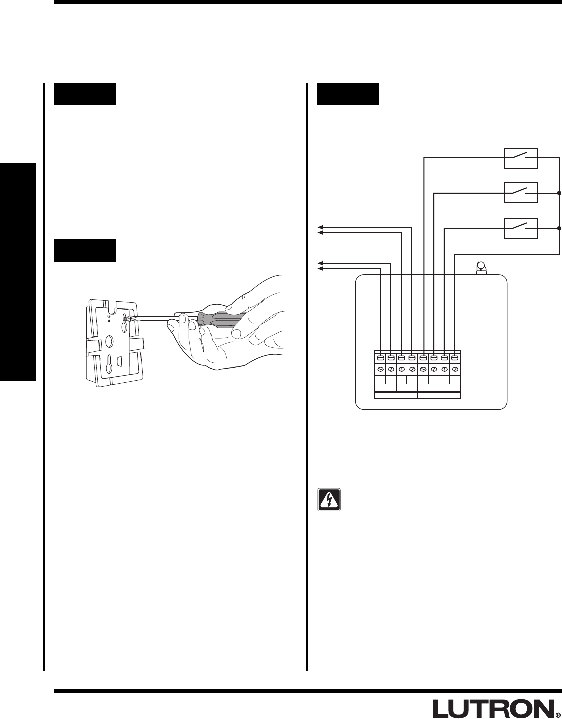
Step 2 Mount Wall Bracket
Step 3 Wiring to input and output
devices.
Attach wall bracket to wall using the
supplied screws and wall anchors.
To Garage
Door Opener 1
To Garage
Door Opener 2 From Input
Device 2
From Input
Device 1
From Security
System
Note:
• Input devices can be timeclocks, motion sensors,
telephone interfaces, etc.
DANGER -
• Do not connect line voltage power to the
Entry Master Control.
• Connecting line voltage power or improper
wiring can result in personal injury or damage
to the control or to other equipment.
• All external control equipment must maintain
Class 2 isolation.
UP
Common
External Switch
Closures (by
customer)
RadioRA
®
Setup Guide for the Entry Master Control
9
Section 2 - Installation
Installing an Entry Master Control
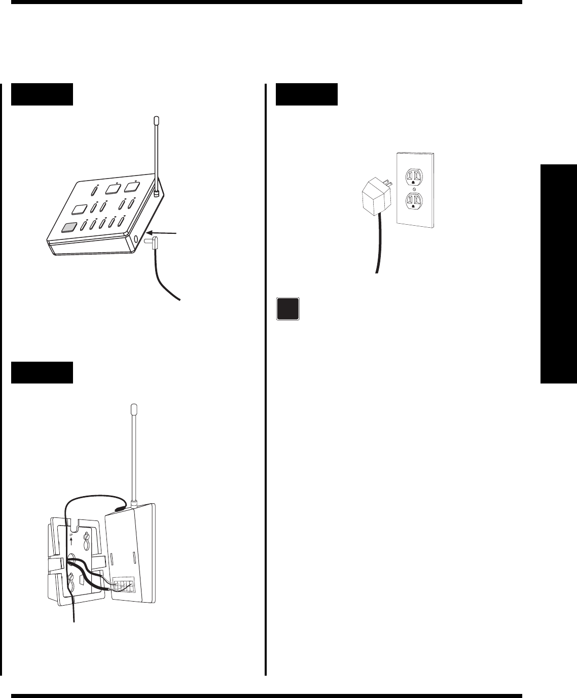
Step 4 Attach the AC Adapter Step 6 Plug in the AC Adapter
Plug the AC Adapter into a 120VAC, 60Hz wall
receptacle.
Align Entry Master Control
and snap onto wall
bracket.
If the LEDs do not flash when powered,
ensure that the AC adapter is installed
properly and that there is power at the
receptacle. If problem persists, call the
Lutron Technical Support Center at
(800) 523-9466.
Plug in power
cord.
?
UP
Step 5 Attach to Wall Bracket
RadioRA
®
Setup Guide for the Entry Master Control
10
Section 3 - Start-Up
Activating an Entry Master Control
Activating Control
The Entry Master Control is a type of Master Control. The RadioRA® System can have a maximum of 12 Master
Controls.
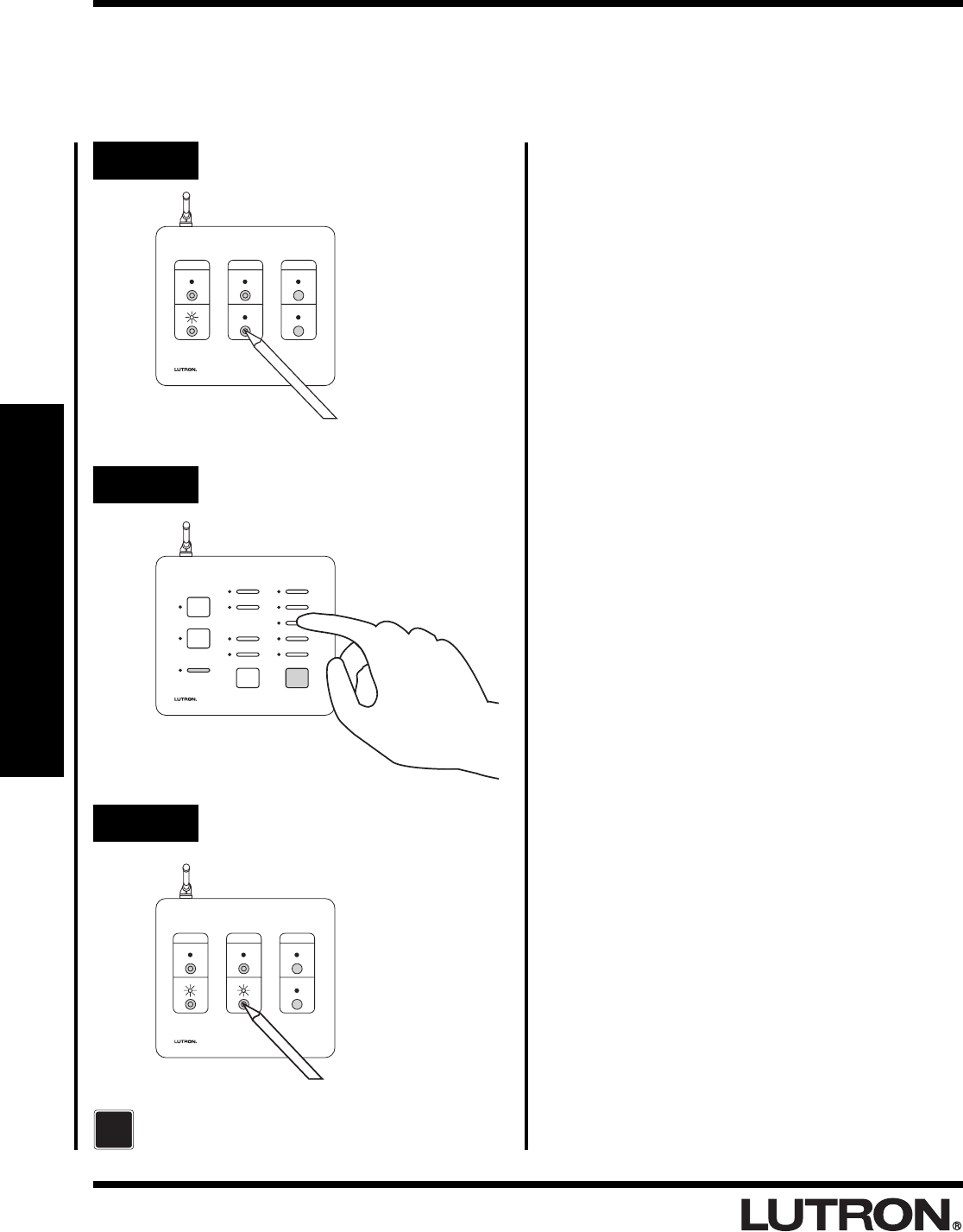
Step 1 Begin Control activation
Step 2 Activate Entry Master Control
SECURITY
CCI 2
CCI 1
FLASH
FULL
CCO 2
CCO 1
LEARN
Step 3 Complete Control activation
For more detailed information, refer to the
RadioRA® Setup Guide (P/N 044-001)
?
MAIN
REPEATER
REPEATER
CONTROLS
ACTIVATE
BEEP
FLASH
VERIFY
AUXILIARY
MAIN
REPEATER
REPEATER
CONTROLS
ACTIVATE
BEEP
FLASH
VERIFY
AUXILIARY
Press and hold button for
3 seconds.
Press button.
Press and hold button for
3 seconds.
RadioRA
®
Setup Guide for the Entry Master Control
11
Section 3 - Start-Up
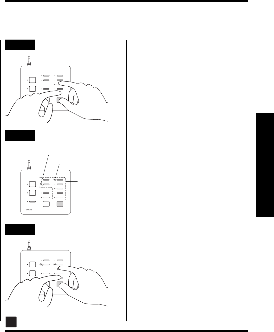
Assigning a Column of Buttons as ROOMS or SCENES
Step 1 Begin ROOM/SCENE
assignment
SECURITY
CCI 2
CCI 1
FLASH
FULL
CCO 2
CCO 1
LEARN
SECURITY
CCI 2
CCI 1
FLASH
FULL
CCO 2
CCO 1
LEARN
ROOMS
Only these
buttons are
configurable.
Step 2 Change ROOM/SCENE
Assignment
Step 3 Complete ROOM/SCENE
assignment
SECURITY
CCI 2
CCI 1
FLASH
FULL
CCO 2
CCO 1
LEARN
For more detailed information, refer to the
RadioRA® Setup Guide (P/N 044-001)
?
SCENES
Button Programming
Press and hold buttons
for 3 seconds.
Press corresponding
button to assign
column as ROOM or
SCENES.
Press and hold buttons
for 3 seconds.
RadioRA
®
Setup Guide for the Entry Master Control
12
Section 3 - Start-Up
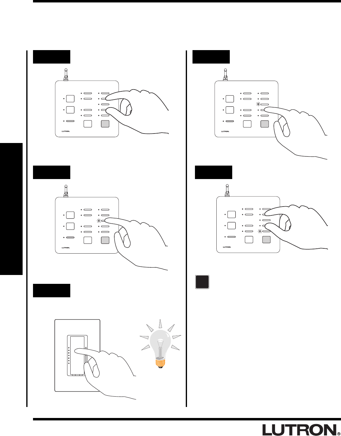
Assigning Dimmers, Switches, or GRAFIK Eye® Control
Units to Buttons
Step 1 Begin assigning
Step 2 Select a button
SECURITY
CCI 2
CCI 1
FLASH
FULL
CCO 2
CCO 1
LEARN
SECURITY
CCI 2
CCI 1
FLASH
FULL
CCO 2
CCO 1
LEARN
Step 3 Assign a Dimmer, Switch or
GRAFIK Eye® Control Unit
Control to the button
Step 4 Select next button
SECURITY
CCI 2
CCI 1
FLASH
FULL
CCO 2
CCO 1
LEARN
Step 5 Complete assigning
SECURITY
CCI 2
CCI 1
FLASH
FULL
CCO 2
CCO 1
LEARN
For more detailed information, refer to the
RadioRA® Setup Guide (P/N 044-001)
?
Button Programming
Press and hold buttons
for 3 seconds.
Press button.
Press tapswitch.
Press button.
Press and hold buttons
for 3 seconds.
RadioRA
®
Setup Guide for the Entry Master Control
13
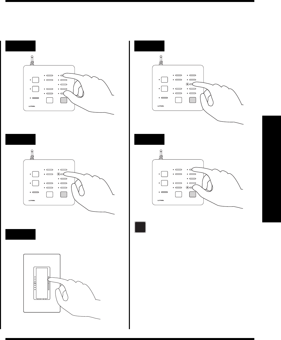
Section 3 - Start-Up
Step 1 Begin setting light levels
SECURITY
CCI 2
CCI 1
FLASH
FULL
CCO 2
CCO 1
LEARN
Step 3 Set light levels for Dimmers or
GRAFIK Eye® scenes
Step 2 Select a button
SECURITY
CCI 2
CCI 1
FLASH
FULL
CCO 2
CCO 1
LEARN
Step 6 Complete setting light levels
Step 5 Select the next button
SECURITY
CCI 2
CCI 1
FLASH
FULL
CCO 2
CCO 1
LEARN
SECURITY
CCI 2
CCI 1
FLASH
FULL
CCO 2
CCO 1
LEARN
For more detailed information, refer to the
RadioRA® Setup Guide (P/N 044-001)
?
Button Programming
Setting Light Levels/GRAFIK Eye® Scene Selection for
Buttons
Press and hold buttons
for 3 seconds.
Press button.
Press raise or lower to set
level.
Press button.
Press and hold buttons
for 3 seconds.
RadioRA
®
Setup Guide for the Entry Master Control
14
Section 3 - Start-Up
Button Programming
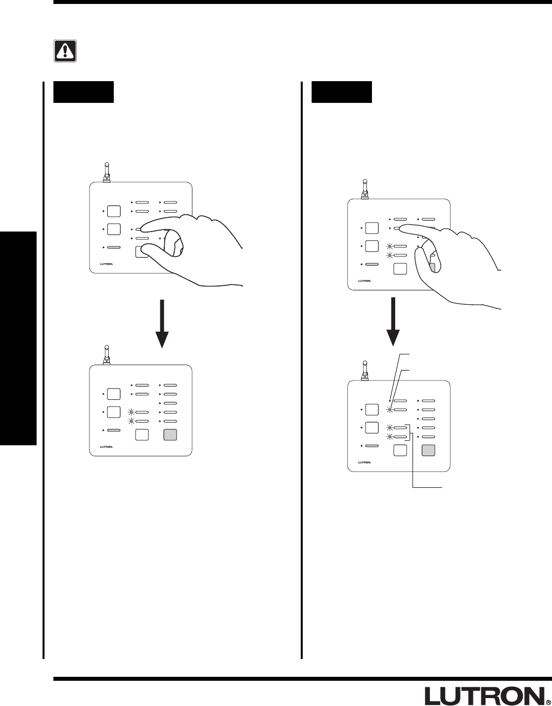
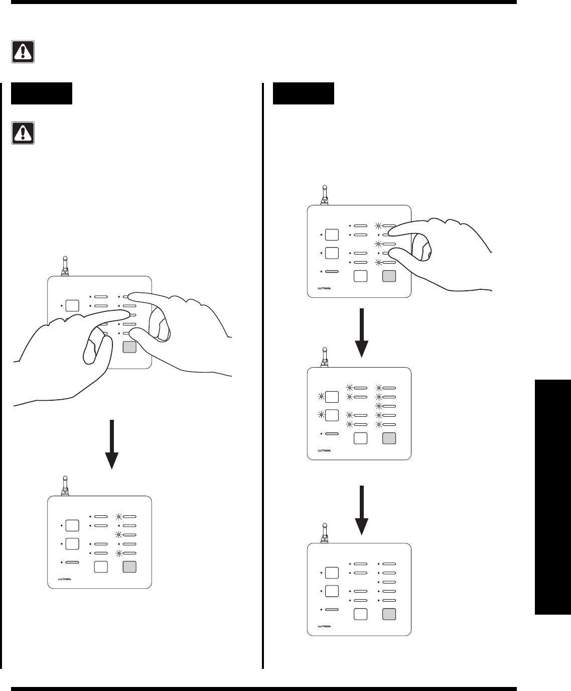
Configuring General Inputs as Maintained or Momentary
Note: The Security Input is always a maintained CCI.
Step 1 Begin CCI closure type
assignment
Simultaneously press and hold the FULL and
ALL ON buttons (approximately 3 seconds).
Step 2 Changing the CCI closure type
assignments
Both General CCIs can be independently
selected as a Momentary or Maintained
closure. Press and hold a CCI button to
change it’s type.
Shown: Setting CCI 2
as Maintained.
SECURITY
CCI 2
CCI 1
FLASH
FULL
CCO 2
CCO 1
LEARN
SECURITY
CCI 2
CCI 1
FLASH
FULL
CCO 2
CCO 1
LEARN
SECURITY
CCI 2
CCI 1
FLASH
FULL
CCO 2
CCO 1
LEARN
FULL and FLASH LEDs will turn ON.
SECURITY
CCI 2
CCI 1
FLASH
FULL
CCO 2
CCO 1
LEARN
LED OFF = Momentary
LED ON = Maintained
Always Maintained
RadioRA
®
Setup Guide for the Entry Master Control
15
Section 3 - Start-Up
Button Programming
Step 3 Complete CCI closure type
assignment
Simultaneously press and hold the FULL and
ALL ON buttons (approximately 3 seconds).
SECURITY
CCI 2
CCI 1
FLASH
FULL
CCO 2
CCO 1
LEARN
SECURITY
CCI 2
CCI 1
FLASH
FULL
CCO 2
CCO 1
LEARN
Activate
Switch
Release
Switch
Switch
Open
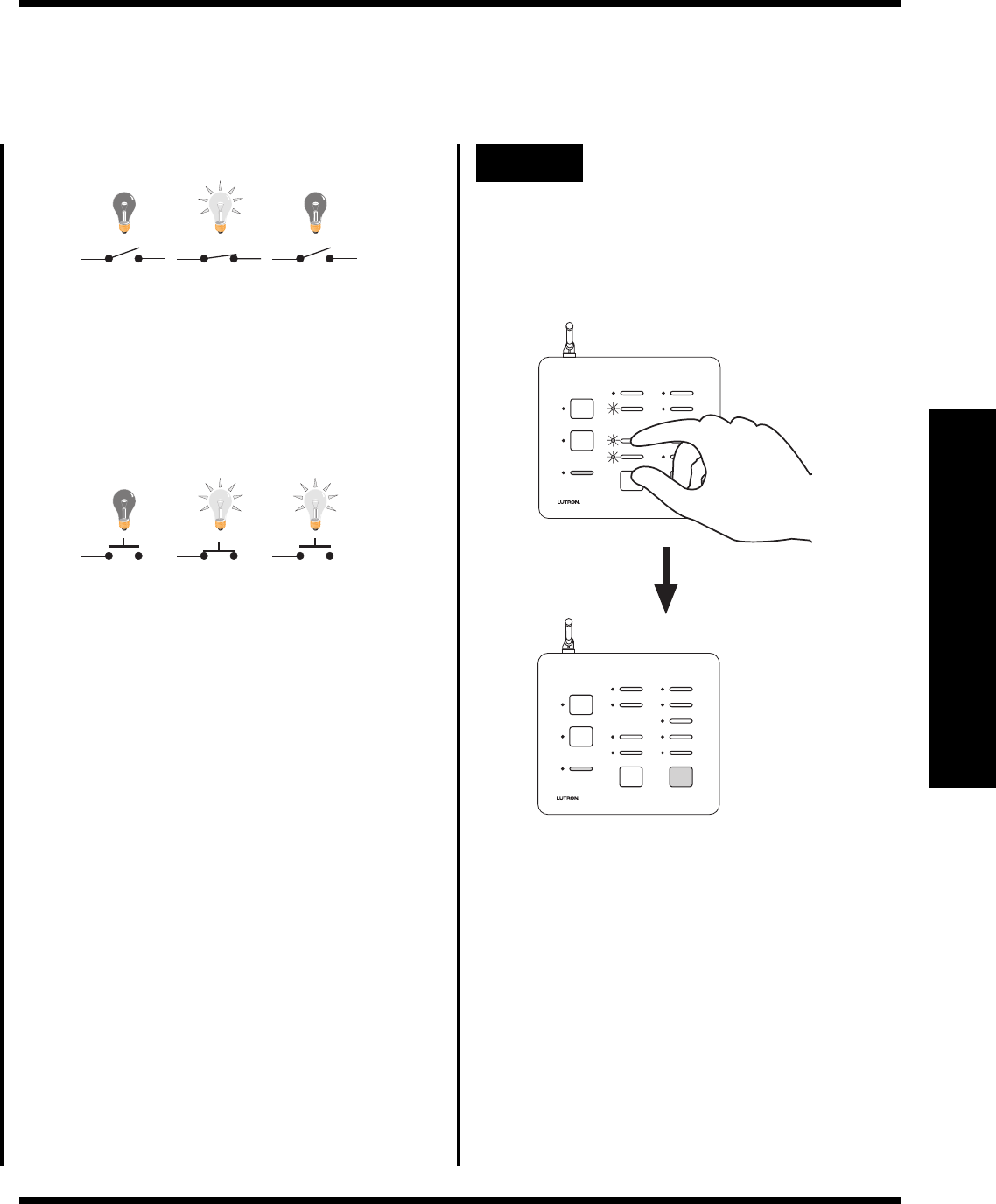
Momentary Input Example
Activate
Switch
Release
Switch
Switch
Open
A Maintained switch closure will turn an input
ROOM or SCENE ON. Input ROOM or
SCENE remains ON until the switch closure is
released. When released, the input ROOM or
SCENE turns OFF.
Maintained Input Example
A Momentary switch closure will turn an input
ROOM or SCENE ON. A momentary switch
closure
cannot
turn an input ROOM or
SCENE OFF.
All LEDs will turn OFF.
RadioRA
®
Setup Guide for the Entry Master Control
16
Section 3 - Start-Up
AWAY
NIGHT
HOME
MORNING
WELCOME
ALL ON ALL OFF
SECURITY
FLASH
FULL
CCO 2
CCO 1
LEARN
GARAGE 1
GARAGE 2
SUNRISE
SUNSET
AWAY
NIGHT
HOME
MORNING
WELCOME
ALL ON ALL OFF
SECURITY
FLASH
FULL
CCO 2
CCO 1
LEARN
GARAGE 1
GARAGE 2
SUNRISE
SUNSET
AWAY
NIGHT
HOME
MORNING
WELCOME
ALL ON ALL OFF
SECURITY
FLASH
FULL
CCO 2
CCO 1
LEARN
GARAGE 1
GARAGE 2
SUNRISE
SUNSET
AWAY
NIGHT
HOME
MORNING
WELCOME
ALL ON ALL OFF
SECURITY
FLASH
FULL
CCO 2
CCO 1
LEARN
GARAGE 1
GARAGE 2
SUNRISE
SUNSET
Step 3 Select an Entry Master Control
Button
Press and release Entry Master Control button
that you want to learn a Visor Control button;
its LED will turn ON.
LED turns ON.
Entry Master Control Learning a Visor Control
Step 1 Plan which Entry Master
Control buttons you want to
learn Visor Control buttons
Button Programming
Step 2 Enter LEARN Mode
Press and hold the LEARN button on the Entry
Master Control until the green LEARN LED
turns ON (approximately 3 seconds).
The green LEARN LED turns ON.
AWAY
NIGHT
HOME
MORNING
WELCOME
ALL ON ALL OFF
SECURITY
FLASH
FULL
CCO 2
CCO 1
LEARN
GARAGE 1
GARAGE 2
SUNRISE
SUNSET
HOME AWAY GARAGE 1
• If the ALL ON button is selected, LEDs in
the right most column will cycle upward.
• If the ALL OFF button is selected, LEDs in
the right most column will cycle downward.
• If either FULL or FLASH is selected, both
the FULL and FLASH LEDs will turn ON.
RadioRA
®
Setup Guide for the Entry Master Control
17
Section 3 - Start-Up
AWAY
NIGHT
HOME
MORNING
WELCOME
ALL ON ALL OFF
SECURITY
FLASH
FULL
CCO 2
CCO 1
LEARN
GARAGE 1
GARAGE 2
SUNRISE
SUNSET
AWAY
NIGHT
HOME
MORNING
WELCOME
ALL ON ALL OFF
SECURITY
FLASH
FULL
CCO 2
CCO 1
LEARN
GARAGE 1
GARAGE 2
SUNRISE
SUNSET
AWAY
NIGHT
HOME
MORNING
WELCOME
ALL ON ALL OFF
SECURITY
FLASH
FULL
CCO 2
CCO 1
LEARN
GARAGE 1
GARAGE 2
SUNRISE
SUNSET
HOME AWAY GARAGE 1
Button Programming
Step 4 Select Visor Control Button to
be learned by the Entry Master
Control
Press and hold the Visor Control Button until
the orange LED next to the selected Entry
Master Control button flashes (approximately
3 seconds). The LEARN LED will also flash
while the Visor Control button is pressed.
The orange LED will turn OFF after the Visor
Control button is released. The green LEARN
LED will stay ON.
•To verify that the Entry Master Control
button has learned the Visor Control
buton, press the Visor Control button
again. The orange LED on the Entry
Master Control will flash.
Step 6 Exit LEARN Mode
Press the LEARN button.
The green LEARN LED turns OFF.
Step 5 Repeat Steps 3 and 4 to learn
additional Visor Control
buttons

RadioRA
®
Setup Guide for the Entry Master Control
18
Section 4 - Advanced Features
Advanced Programming
Programming the ALL ON Button
To program the ALL ON button, refer to the RadioRA® Setup Guide, Lutron P/N 044-001, section on
“Programming the ALL ON Button.”
Programming the ALL OFF Button
To program the ALL OFF button, refer to the RadioRA® Setup Guide, Lutron P/N 044-001, section on
“Programming the ALL OFF Button.”
Copying Button Programming
To copy button programming from another Master Control button, refer to the RadioRA® Setup Guide, Lutron P/N
044-001, section on “Copying Button Programming.”
Erasing Button Programming
To erase button programming from the Entry Master Control, refer to the RadioRA® Setup Guide, Lutron P/N 044-
001, section on “Erasing Button Programming.”
RadioRA
®
Setup Guide for the Entry Master Control
19
Section 4 - Advanced Features
Advanced Programming
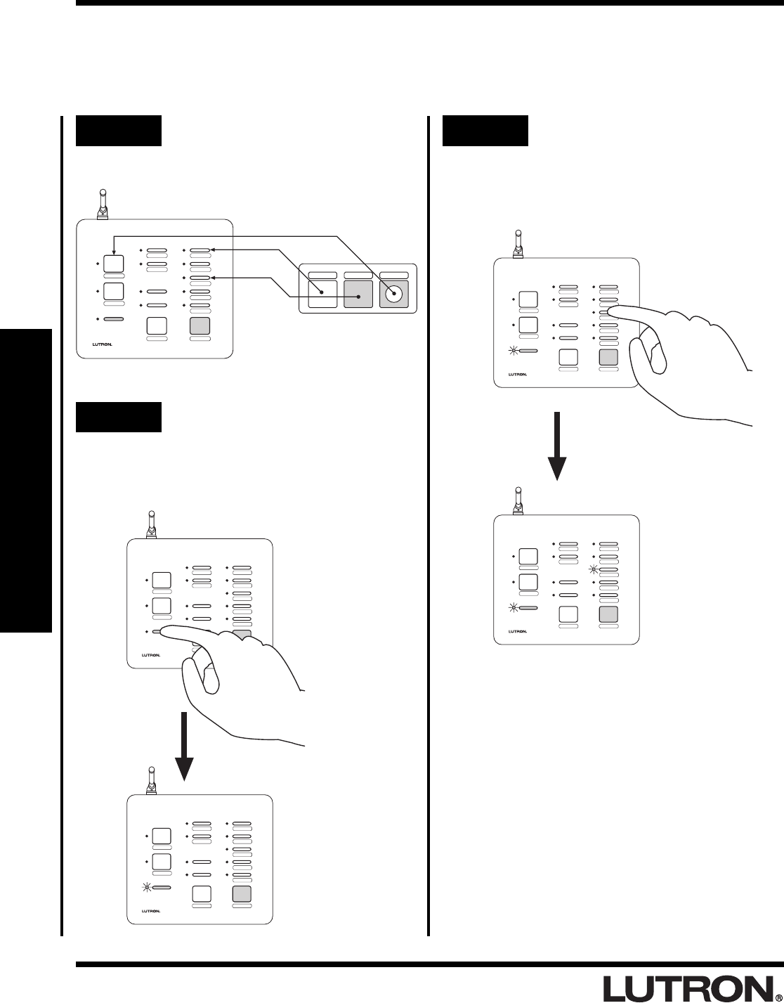
Programming the FULL and FLASH Buttons
The Security FULL and FLASH buttons are used for programming and diagnostic purposes only.
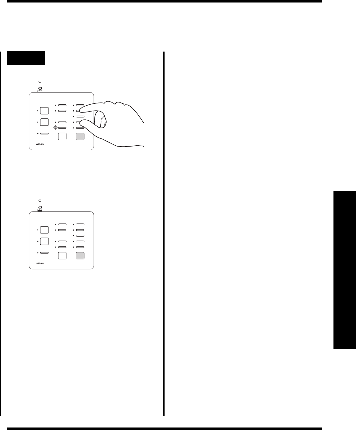
Step 1 Begin FULL and FLASH
button programming
Simultaneously press and hold the 2nd and
4th buttons in the right most column until the
upper right LED begins to flash (approximately
3 seconds).
Upper right LED flashes.
Step 2 Select the FULL Button
Press the FULL button.
SECURITY
CCI 2
CCI 1
FLASH
FULL
CCO 2
CCO 1
LEARN
SECURITY
CCI 2
CCI 1
FLASH
FULL
CCO 2
CCO 1
LEARN
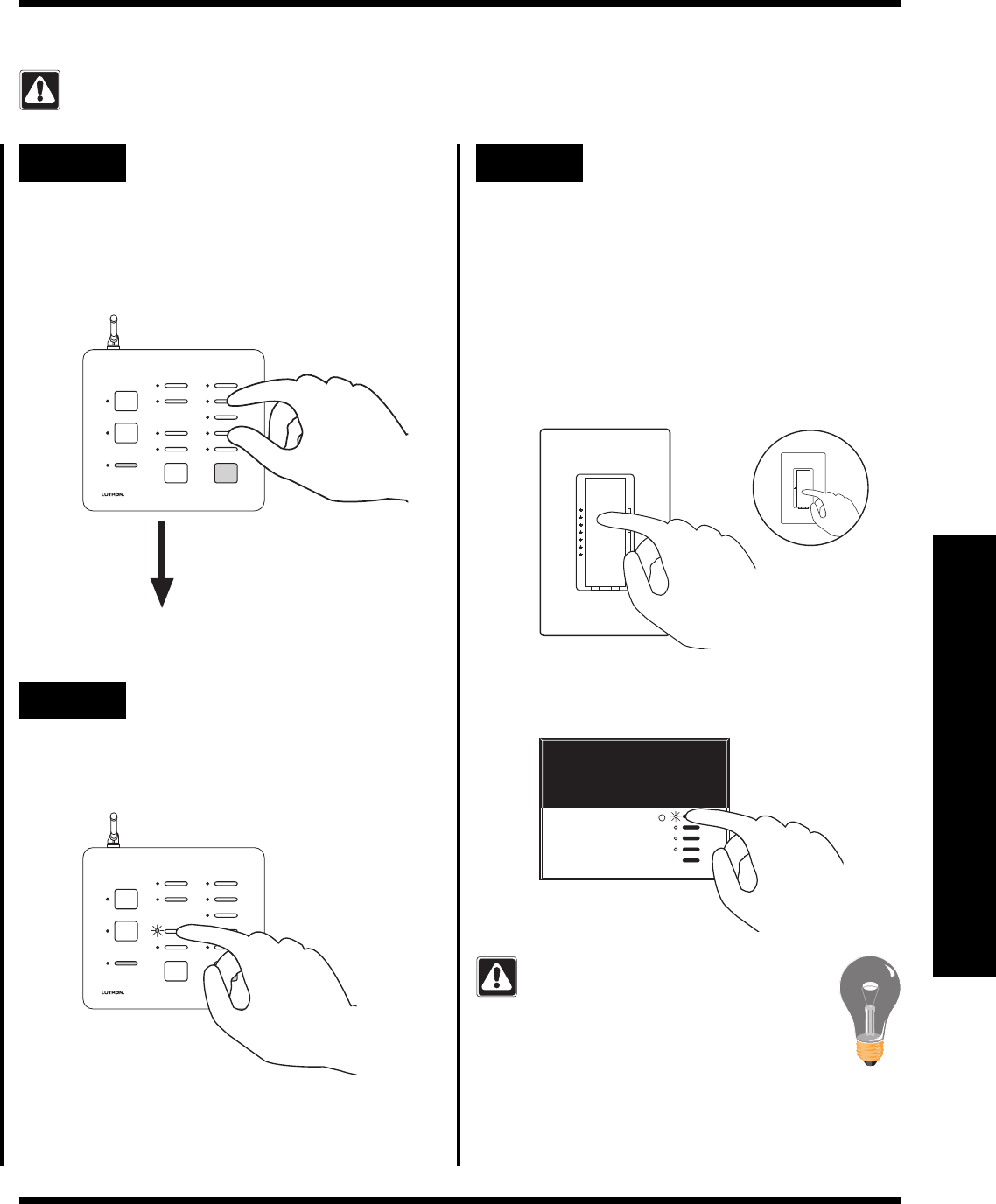
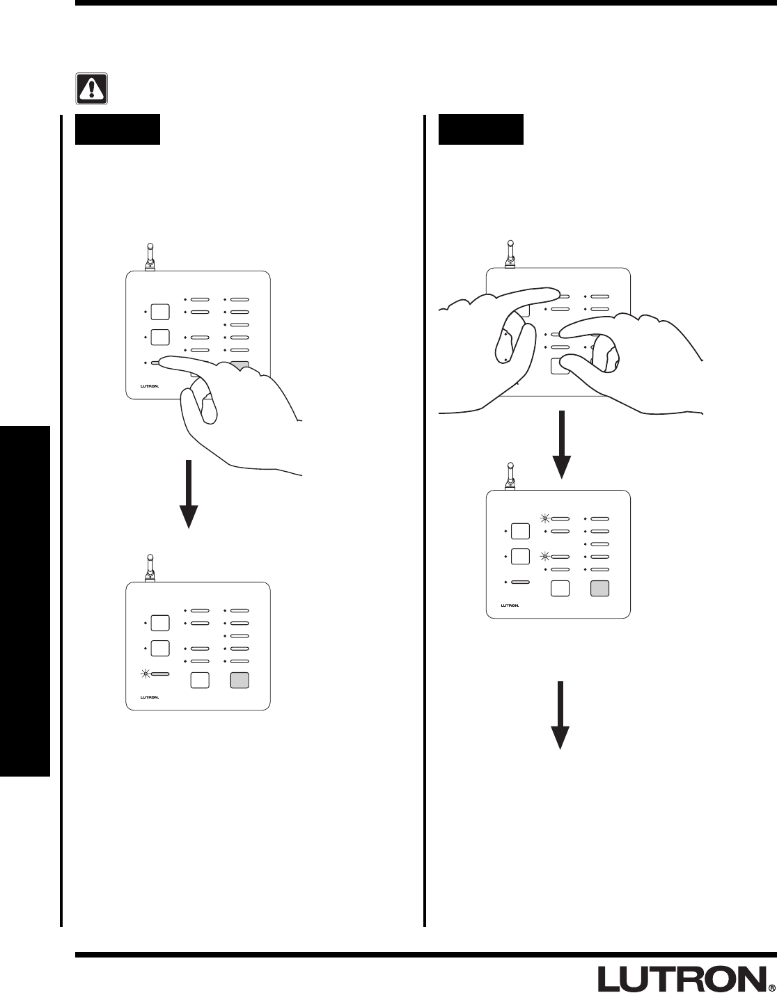
Step 3 Assign Dimmers, Switches or
GRAFIK Eye® Control Units to
the FULL button
• Dimmers and Switches assigned will turn on to full
while in SECURITY Mode.
• GRAFIK Eye® Control Units assigned will go to
scene 1 while in SECURITY Mode.
If you assign the wrong Dimmer,
Switch or GRAFIK Eye® Control Unit to
the FULL button, turn the Dimmer,
Switch or GRAFIK Eye® Control Unit
OFF to unassign it.
Assign a GRAFIK Eye® Control Unit to the
FULL button by pressing the scene 1 button.
Assign a Dimmer or Switch to the FULL button
by turning the Dimmer or Switch ON.
Switch
OR
Dimmer
•Continued on next page.
FULL LED will begin to flash.
LUTRON
RadioRA
®
Setup Guide for the Entry Master Control
20
Section 4 - Advanced Features
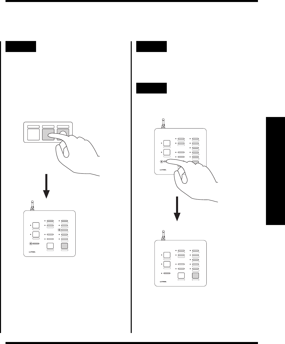
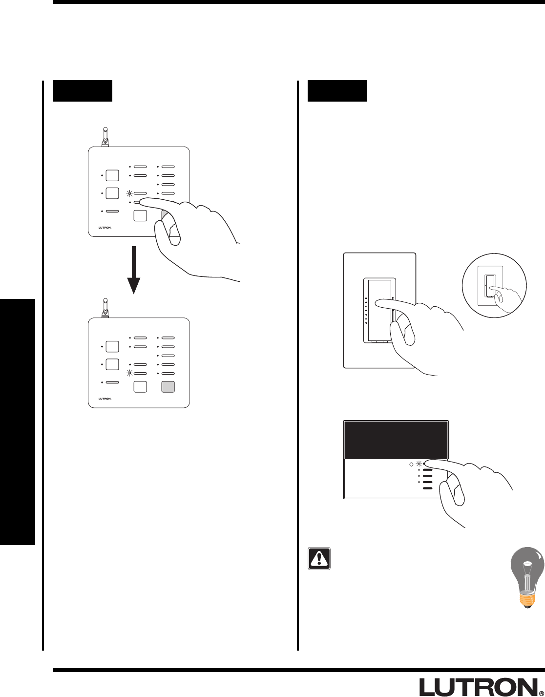
Step 4 Select FLASH button
Press the FLASH button.
FLASH LED will begin to flash.
SECURITY
CCI 2
CCI 1
FLASH
FULL
CCO 2
CCO 1
LEARN
SECURITY
CCI 2
CCI 1
FLASH
FULL
CCO 2
CCO 1
LEARN
Advanced Programming
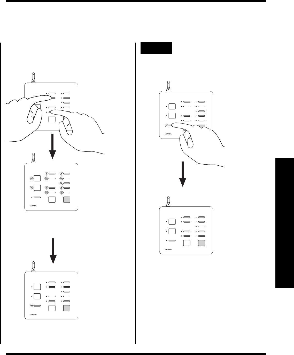
Step 5 Assign Dimmers, Switches or
GRAFIK Eye® Control Units to
the FLASH button
• Dimmers and Switches assigned will flash ON and
OFF while in SECURITY Mode.
• GRAFIK Eye® Control Units assigned will alternate
between scene 1 and OFF while in SECURITY
Mode.
If you assign the wrong Dimmer,
Switch or GRAFIK Eye® Control Unit to
the FLASH button, turn the Dimmer,
Switch or GRAFIK Eye® Control Unit
OFF to unassign it.
Assign a Dimmer or Switch to the FLASH
button by turning the Dimmer or Switch ON.
Switch
OR
Dimmer
Assign a GRAFIK Eye® Control Unit to the
FLASH button by pressing the scene 1 button.
LUTRON
RadioRA
®
Setup Guide for the Entry Master Control
21
Section 4 - Advanced Features
Step 6 Complete FULL and FLASH
button programming
Simultaneously press and hold the 2nd and
4th buttons in the right most column until all
the LEDs begin to flutter (approximately 3
seconds).
SECURITY
CCI 2
CCI 1
FLASH
FULL
CCO 2
CCO 1
LEARN
SECURITY
CCI 2
CCI 1
FLASH
FULL
CCO 2
CCO 1
LEARN
Advanced Programming
RadioRA
®
Setup Guide for the Entry Master Control
22
Section 4 - Advanced Features
Deleting ALL Visor Control Transmitters from an Entry
Master Control
Deleting all Visor Controls from an Entry Master Control will permanently delete all Visor Control
Transmitter Buttons previously learned.
Step 1 Begin deleting ALL Visor
Controls
Step 2 Delete ALL Visor Controls
Press and hold the CCI 1, FULL, and ALL ON
buttons in the middle column until the CCI 1
and FULL LEDs begin to flash (approximately
3 seconds).
The CCI 1 and FULL LEDs flash.
SECURITY
CCI 2
CCI 1
FLASH
FULL
CCO 2
CCO 1
LEARN
SECURITY
CCI 2
CCI 1
FLASH
FULL
CCO 2
CCO 1
LEARN
Press and hold the LEARN button until its LED
turns ON (approximately 3 seconds).
The green LEARN LED turns ON.
SECURITY
CCI 2
CCI 1
FLASH
FULL
CCO 2
CCO 1
LEARN
SECURITY
CCI 2
CCI 1
FLASH
FULL
CCO 2
CCO 1
LEARN
Advanced Programming
RadioRA
®
Setup Guide for the Entry Master Control
23
Section 4 - Advanced Features
Advanced Programming
Step 3 Complete deleting ALL Visor
Controls
Press the LEARN button.
The green LEARN LED turns OFF.
SECURITY
CCI 2
CCI 1
FLASH
FULL
CCO 2
CCO 1
LEARN
SECURITY
CCI 2
CCI 1
FLASH
FULL
CCO 2
CCO 1
LEARN
All LEDs will turn OFF (except the LEARN),
indicating that ALL Visor Controls have been
deleted from the Entry Master Control.
SECURITY
CCI 2
CCI 1
FLASH
FULL
CCO 2
CCO 1
LEARN
While the CCI 1 and FULL LEDs are
flashing, press and hold the CCI 2 and
FLASH buttons in the middle column until all
the LEDs flash.
SECURITY
CCI 2
CCI 1
FLASH
FULL
CCO 2
CCO 1
LEARN
SECURITY
CCI 2
CCI 1
FLASH
FULL
CCO 2
CCO 1
LEARN
All LEDs (except the LEARN) flutter.
RadioRA
®
Setup Guide for the Entry Master Control
24
Section 5 - Troubleshooting
Troubleshooting Guide
Proper operation of the RadioRA® Wireless Central Home Lighting Control System is based upon a complex
series of radio frequency (RF) communications between system components. As such, it is highly dependent
upon proper system installation and programming of controls.
If you experience difficulties programming or operating your RadioRA® system, please refer to this guide.
Many symptoms of common system activation or programming errors are contained in this Troubleshooting
Guide. If you are having a problem with your system not described here, or if you have any questions, call
the
Lutron Technical Support Center
at 1-800-523-9466.
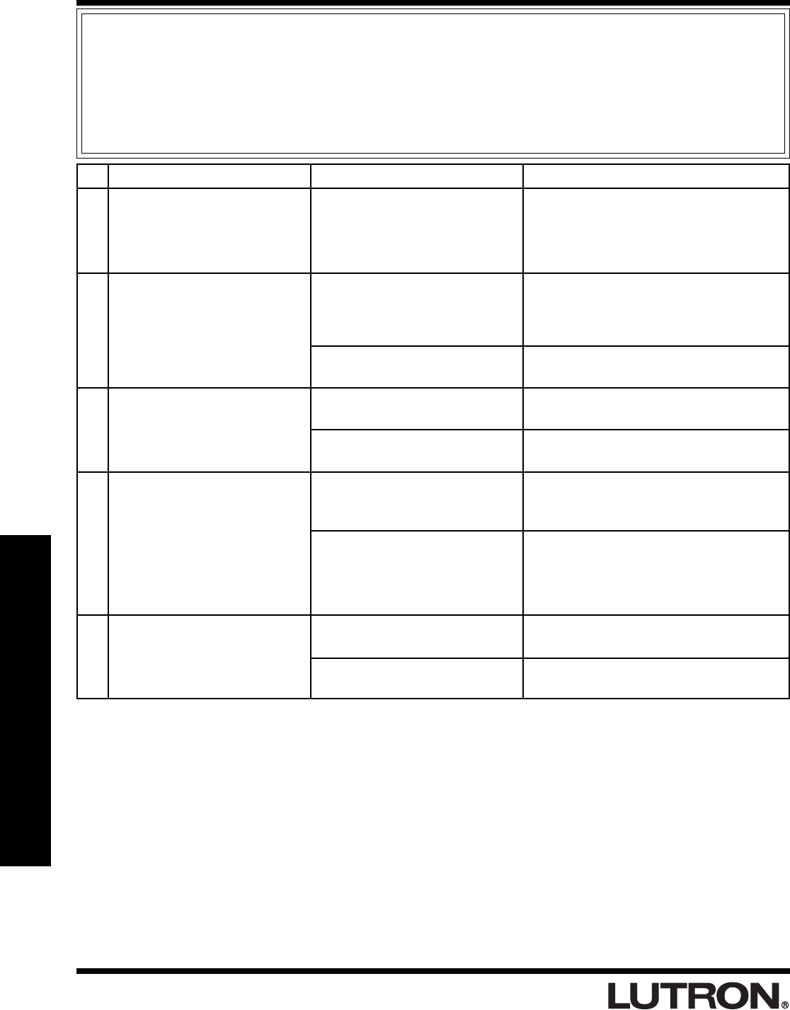
Symptom Possible Cause Remedy
Discontinue activating your RadioRA®
system until activation of the neighboring
system is complete.
Move a system Repeater closer to the
Multi-Function Entry Master Control in
question, or you may have to add another
Repeater.
Place system in ACTIVATE CONTROLS
mode.
Check that breaker is on and not tripped.
Verify that the plug in power supply is
working.
Reprogram the Multi-Function Entry
Master Control.
Verify whether the Multi-Function Entry
Master Control is in range of a Repeater
by placing the system in BEEP mode.
(Refer to the Troubleshooting Section in
the RadioRA® Setup Guide P/N 044-001.)
Entry Master Control must learn Visor
Control Transmitter.
Replace batteries in Visor Control
Transmitter with new ones (CR2032).
I
II
III
IV
V
ACTIVATE CONTROLS LED on
MAIN or AUXILIARY Repeater
turns ON and then back OFF
when attempting to go into
ACTIVATE CONTROLS mode.
After activating a Multi-Function
Entry Master Control, the Multi-
Function Entry Master Control
LEDs flutter for approximately 5
seconds then go out.
The Multi-Function Entry Master
Control appears not to be
working at all and the LEDs are
OFF.
The Multi-Function Entry Master
Control appears not to be
working at all and the LEDs are
glowing dimly.
The Visor Control Transmitter is
not communicating with the
Multi-Function Entry Master
Control.
Your system has encountered a
neighboring system within RF
communication range also in
ACTIVATE CONTROLS mode.
Multi-Function Entry Master
Control is out of RF communica-
tion range of nearest system
Repeater.
System not in ACTIVATE
CONTROLS mode.
No power available to the Multi-
Function Entry Master Control.
Faulty power supply.
The Multi-Function Entry Master
Control was not programmed
properly.
The Multi-Function Entry Master
Control may be out of RF
communication range of the
nearest Repeater.
Entry Master Control failed to
learn Visor Control Transmitter.
Batteries weak or dead.
RadioRA
®
Setup Guide for the Entry Master Control
25
Section 5 - Troubleshooting
Returning to Default Factory Settings
Entry Master Control
Returning an Entry Master Control to Default Factory Settings will permanently delete all current
programming information. Do not do this unless you are sure that it is necessary. For more information
call the
Lutron Technical Support Center at 1-800-523-9466.
Step 1 Begin returning to Default
Factory Settings
Step 2 Complete returning to Default
Factory Settings
Ensure that the ACTIVATE REPEATER LED
and ACTIVATE CONTROLS LED on any
Repeater is NOT ON before proceeding. If
either LED is ON, press the corresponding
button until its LED turns OFF (approximately 3
seconds).
Press and hold the 1st, 3rd and 5th buttons in
the right most column until the corresponding
LEDs begin to flash (approximately 3
seconds).
LEDs will flash for only 3 seconds.
SECURITY
CCI 2
CCI 1
FLASH
FULL
CCO 2
CCO 1
LEARN
SECURITY
CCI 2
CCI 1
FLASH
FULL
CCO 2
CCO 1
LEARN
While the 1st, 3rd, and 5th LED are
flashing, press and hold the 2nd and 4th
buttons in the right most column until all the
LEDs (except the LEARN) flash
(approximately 3 seconds).
All LEDs will turn OFF, indicating that the
Master Control has been returned to Default
Factory Settings.
SECURITY
CCI 2
CCI 1
FLASH
FULL
CCO 2
CCO 1
LEARN
All LEDs (except the LEARN) flash.
SECURITY
CCI 2
CCI 1
FLASH
FULL
CCO 2
CCO 1
LEARN
SECURITY
CCI 2
CCI 1
FLASH
FULL
CCO 2
CCO 1
LEARN

RadioRA
®
Setup Guide for the Entry Master Control
26
Section 5 - Troubleshooting
Notes

RadioRA
®
Setup Guide for the Entry Master Control
27
Section 5 - Troubleshooting
Notes

RadioRA
®
Setup Guide for the Entry Master Control
28
World Headquarters
Lutron Electronics Co., Inc.
7200 Suter Road
Coopersburg, PA 18036-1299 U.S.A.
TOLL FREE: (800) 523-9466 (U.S.A., Canada, and
the Caribbean)
Tel: (610) 282-3800
Fax: (610) 282-3090
Lutron Electronics Co., Inc., reserves the right to make
improvements or changes in its products without prior
notice. Although every attempt is made to ensure that
this information is accurate and up to date, please
check with Lutron to confirm product availability, latest
specifications and suitability for your application.
© 2001 Lutron Electronics Co., Inc.
MADE AND PRINTED IN U.S.A.
P/N 044-022 11/01 Rev. A
Technical Assistance
If you have questions concerning the installation or
operation of this product, call the
Lutron Technical
Support Center.
Please provide exact model number
when calling.
(800) 523-9466 (U.S.A., Canada, and the Caribbean)
Other countries call (610) 282-3800
Fax (610) 282-3090
Visit our web site at www.lutron.com
Limited Warranty
Lutron will, at its option, repair or replace any unit that
is defective in materials or manufacture within one
year after purchase. For warranty service, return unit
to place of purchase or mail to Lutron Electronics Co.,
Inc. at 7200 Suter Rd., Coopersburg, PA 18036-1299,
postage pre-paid.
THIS WARRANTY IS IN LIEU OF ALL OTHER
EXPRESS WARRANTIES, AND THE IMPLIED
WARRANTY OF MERCHANTABILITY IS LIMITED
TO ONE YEAR FROM PURCHASE. THIS
WARRANTY DOES NOT COVER THE COST OF
INSTALLATION, REMOVAL OR REINSTALLATION,
OR DAMAGE RESULTING FROM MISUSE, ABUSE,
OR DAMAGE FROM IMPROPER WIRING OR
INSTALLATION. THIS WARRANTY DOES NOT
COVER INCIDENTAL OR CONSEQUENTIAL
DAMAGES. LUTRON’S LIABILITY ON ANY CLAIM
FOR DAMAGES ARISING OUT OF OR IN
CONNECTION WITH THE MANUFACTURE, SALE,
INSTALLATION, DELIVERY, OR USE OF THE UNIT
SHALL NEVER EXCEED THE PURCHASE PRICE
OF THE UNIT.
This warranty gives you specific legal rights, and you
may have other rights which vary from state to state.
Some states do not allow the exclusion or limitation of
incidental or consequential damages, or limitation on
how long an implied warranty may last, so the above
limitations may not apply to you.
This product may be covered under one or more of the
following U.S. patents: 4,835,343; 4,954,768;
5,248,919; 5,399,940; 5,637,930; 5,736,965;
5,798,581; 5,838,226; 5,848,054; 5,905,442;
5,982,103; DES 353,798; DES 378,814; DES 389,461;
DES 389,805; DES 395,037; DES 404,013;
DES 422,969; DES 428,855; DES 436,579;
DES 439,220 and corresponding foreign patents. U.S.
and foreign patents pending. Lutron, RadioRA, and
GRAFIK Eye are registered trademarks, and FASS is
a trademark of Lutron Electronics Co., Inc.
© 2001 Lutron Electronics Co., Inc.