Lutron Electronics 0063 RF Keypad User Manual 2
Lutron Electronics Company Inc RF Keypad 2
Contents
- 1. User Manual 1
- 2. User Manual 2
- 3. User Manual
User Manual 2
RRD-W6BRL RRD-W7B
RRD-W5BRLIR
RRD-W3BRL
RRD-W3BD
Mounting Diagram
English
Use these instructions to install the model numbers listed above.
For system setup instructions and tools visit:
www.lutron.com/radiora2
Important Notes
Codes: Install in accordance with all local and national electrical codes.
Environment: Ambient operating temperature: 32 °F to 104 °F (0 °C to 40 °C),
0 to 90% humidity, non-condensing. Indoor use only.
Wallplates: Use only Lutron® wallplates with these devices. The mechanical
design of the keypad is NOT compatible with non-Lutron wallplates. Non-
Lutron wallplates will NOT sit flush against the wall. Claro® and Satin Colors®
wallplates are strongly recommended for best color match and clean aesthetic
appearance. Do not paint controls, buttons, or wallplates.
Cleaning: To clean, wipe with a clean damp cloth. DO NOT use any chemical
cleaning solutions.
Wallboxes: All keypads require a U.S. wallbox. 3
1⁄2 in (89 mm) deep
recommended, 2
1⁄4 in (57 mm) deep minimum.
RF Device Placement: RF dimmers, switches, keypads and shades/drapes
must be located within 30 ft (9 m) of an RF signal repeater. For systems without
an RF signal repeater, all RF dimmers, switches, keypads and shades/drapes
must be located within 30 ft (9 m) of each other. Remote dimmers and switches
are not required to be within a specific range.
Engraving: The Prepaid Engraving Certificate included with the keypad can
be reedeemed for a custom engraved replacement kit. To order an engraved
replacement kit please follow the instructions at: www.lutron.com/buttons
Lutron Elec tron ics Co., Inc.
7200 Suter Road
Coopersburg, PA 18036-1299
Made and print ed in the U.S.A. 7/09 P/N 044-158 Rev. A
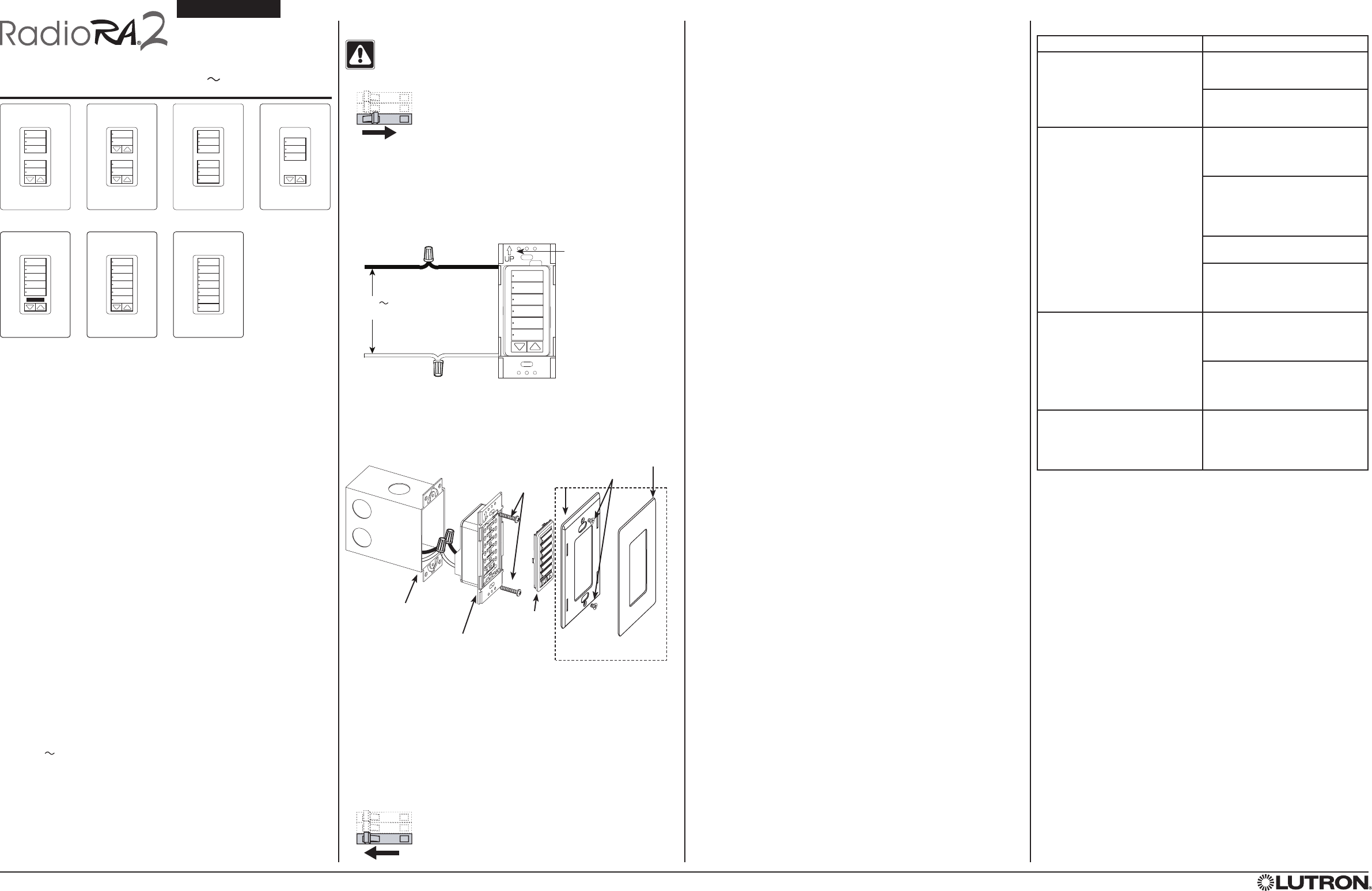
Installation
WARNING: Shock Hazard. To avoid the risk of electric shock, locate
and remove fuse or lock circuit breaker in the OFF position before
proceeding. Wiring with power ON could result in serious injury or
death.
1. Turn power OFF at fusebox or circuit breaker.
2. Prepare wires. When making wire connections, follow the recommended
strip lengths and combinations for the supplied wire connectors. Note: Wire
connectors provided are suitable for copper wire only.
•Strip insulation 3/8 in (10 mm) for 14 AWG (1.5 mm2).
•Strip insulation 1/2 in (13 mm) for 18 AWG (0.75 mm2).
•Use to join one 14 AWG (1.5 mm2) with one 18 AWG (0.75 mm2) wires.
3. Wire control.
4. Push all wires back into the wallbox and loosely fasten the control to the
wallbox using the keypad mounting screws provided. Do not pinch the wires.
See Mounting Diagram below.
NOTE: Orientation arrow
MUST point UP.
Hot/Live Black
Neutral White
5. Install Replacement Kit (if applicable).
6. Attach Lutron Claro or Satin Colors wallplate adapter and wallplate (see
Mounting Diagram).
a. Install the wallplate adapter onto the front of the keypad(s).
b. Tighten keypad mounting screws until wallplate adapter is flush to wall (do
not over-tighten).
c. Snap wallplate onto wallplate adapter and verify that buttons are aligned
properly.
d. If control(s) are misaligned, loosen keypad mounting screws appropriately.
7. Restore power.
Troubleshooting Guide (for Simple Setup)
Symptom Probable Cause and Action
LEDs on a keypad don’t light up
when the buttons on it are pressed.
Power not present at keypad
•CircuitbreakerOFF.TurnON
breaker.
Incorrect wiring.
•Wirethekeypadaccordingtothe
Installation section.
Dimmer, switch or shade/drape not
controlled by a keypad.
The dimmer, switch or shade/drape is
not assigned to keypad.
•Follow the steps in Assigning
devices to a keypad.
The device is ‘unaffected.’
•Follow the steps Saving light
levels and shade/drape
positions to change the
‘unaffected’ status.
The lamps are burned out.
•Replace the lamps.
Either there is no power to the device
or the FASSTM switch is pulled out.
•Ensure that the device is powered
and push FASS switch in.
Dimmer, switch or shade/drape does
not go to desired level when a button
on a keypad is pressed.
The system is not setup correctly.
•Follow the steps in Saving
light levels and shade/drape
positions to set up the system.
The device is ‘unaffected.’
•Follow the steps Saving light
levels / shade/drape positions
to change the ‘unaffected’ status.
All LEDs on the keypad flash when
any button is pressed.
The keypad is in the Factory Settings
mode and has not been configured to
work in a system.
•Follow the steps in Assigning
devices to a keypad.
Note: Refer to the system Setup Guide for additional troubleshooting
suggestions.
Returning Keypads to Factory Settings
Returning a keypad to its Factory Settings will remove the keypad from the
system and erase all programming.
Step 1: Triple tap any button on the keypad. DO NOT release after third tap.
Step 2: Keep the button pressed on the third tap until all the status LEDs start
to flash slowly (approximately 3 seconds).
Step 3: Immediately release the button and triple tap the button again. The
status LEDs on the keypad will flash quickly.
The keypad has now been returned to Factory Settings.
Warranty: For warranty information, please see the Warranty enclosed with the
product, or visit www.lutron.com/resiinfo.
These products may be covered under one or more of the following U.S. patents: 5,838,226; 5,848,054; 5,905,442; 5,982,103; 6,687,487; 6,803,728; D453,742; D456,783; D461,782; D465,460; D465,770 and
corresponding foreign patents and/or design registrations. U.S. and foreign patents may be pending. Lutron, RadioRA, Claro, Satin Colors, and the sunburst logo are registered trademarks and RadioRA 2 and
FASS are trademarks of Lutron Electronics Co., Inc.
©2009 Lutron Electronics Co., Inc.
Replacement
Kit
Keypad
Wallbox
Keypad
Mounting
Screws
Adapter
Mounting
Screws
Wallplate adapter and wallplate
purchased separately.
Wallplate
Wallplate
Adapter
Installation Instructions
Please Read Before Installing
RRD-W2RLD
RRD-W1RLD
Technical Assistance:
U.S.A. / Canada: 1.800.523.9466
Mexico: +1.888.235.2910
Other Countries: +1.610.282.3800
24 hours a day, 7 days a week.
Wall-mount Designer Keypads
RRD-W1RLD, -W2RLD, -W3BD,
-W3BRL, -W5BRLIR, -W6BRL, -7B
120 V 50 / 60 Hz 0.5 A
Typical Power Consumption*: 0.6 W
ON
OFF
ON
OFF
ON
OFF
ON
OFF
ON
OFF
ON
OFF
120 V
50 / 60 Hz
* Typical Power Consumption test conditions: all backlights on medium intensity, two LEDs on (two presets active), keypad
powered at 120 V
Simple Setup
To program a system which contains at least 1 (one) Main Repeater refer to the system
Setup Guide. Follow the instructions below to program a system which does NOT contain
a Main Repeater.
After all devices have been installed, the keypads must be programmed to control a set of
dimmers, switches and shades/drapes. Programming a system which does NOT contain a
Main Repeater consists of two steps:
1. Assigning dimmers, switches, keypads and shades/drapes to keypads
2. Saving the desired light levels and shade/drape positions
Assigning devices to a keypad
1. Enter assign mode – press and hold the top and bottom buttons of the desired keypad
column until the LEDs begin to flash (approximately 6 seconds). If the column was
previously programmed, all of the LEDs in the column will scroll sequentially. If this is the
first time the column is programmed, only the top and bottom LEDs will flash alternately
Note: The keypad will automatically exit assign mode after 10 minutes.
2. Press each keypad button between the top and bottom buttons to add the buttons to
the column. Once pressed, the LED next to a button will flash in sequence with the other
LEDs, indicating that it is now part of the keypad column.
3. Assign devices to the keypad column.
a. Dimmers/switches – press and hold the tapswitch on the device until the load
flashes 3 times (approximately 6 seconds). The LEDs on assigned dimmers
and switches will continue to flash while the keypad is in assign mode.
b. Shades/drapes – press any button on the drive and the LED will flash.
4. Assign other keypad columns – press and hold the bottom button of the keypad
column to be assigned until the LEDs begin to flash (approximately 6 seconds).
Assigning a keypad column to another keypad column is useful for making keypad
LEDs track each other. All keypads assigned to each other should have the same set
of dimmers, switches and shades/drapes assigned to them. While the first keypad is in
assign mode, its LEDs will scroll (if previously programmed) and the LEDs on assigned
keypads will continue to flash simultaneously.
Note: To unassign a device that is assigned, repeat the corresponding method described
in steps 3-4.
5. When all devices have been assigned, exit assign mode by holding the top and
bottom buttons of the column until all the LEDs stop scrolling (approximately 3 seconds).
6. Confirm programming by individually pressing every button on the keypad. Assigned
devices respond to the button press by going to the default level for that button. During
normal operation, when a button is pressed, the LED next to the button is illuminated.
The LED turns off after another button is pressed on that keypad, on another assigned
keypad, or if a level of a dimmer or switch assigned to the column changes.
Saving light levels and shade/drape positions
You can customize the levels or positions of the devices assigned to a keypad column by
using the steps below. The keypad column containing the button to be customized must
have already been programmed according to Assigning devices to a keypad, above.
1. Press the button you wish to customize. The lights and shades/drapes will move to the
default level(s) and/or position(s) for this button. Wait until the lights and shades/drapes
stop dimming and moving.
2. Adjust each dimmer, switch and shade/drape assigned to that column as follows:
a. Dimmers - use the tapswitch to toggle the lights on or off. Use the raise or lower
button on the right side of the dimmer to make adjustments to the desired light levels.
b. Switches - use the tapswitch to toggle the lights on or off.
c. Shades/drapes - use the clockwise or counter-clockwise buttons on the shade/
drape to adjust the position.
3. Making dimmers, switches and shades/drapes ‘unaffected’ (optional) – to make
assigned devices not respond to a button press, you may make the devices ‘unaffected’.
During normal operation when you press a button, a device that is ‘unaffected’ will
ignore that button press. The light level or shade/drape position will not change. To make
devices ‘unaffected’, follow the corresponding step below based on the type of device
to be made ‘unaffected’.
a. Dimmer – if the dimmer is on, turn it off using the tapswitch. After the dimmer
is completely off, hold the lower rocker until the three middle LEDs turn on
(approximately 6 seconds), signifying that the next save will be ignored. **
b. Switch – if the switch is on, turn it off using the tapswitch. Pull the FASSTM switch
out. Press and hold the tapswitch. While still holding the tapswitch, push the FASS
switch in. Continue holding the tapswitch until the LED flashes, signifying that the
next save will be ignored. **
c. Shade/Drape – if the shade/drape is open, close it using either the clockwise or
counter-clockwise button. Release the button. After the shade/drape is closed, press
and hold the same button used to close the shade/drape until the green LED blinks
quickly (approximately 10 seconds), signifying that the next save will be ignored. **
4. Press and hold the selected keypad button until the LED flashes (approximately 6
seconds) to save the current levels or the ‘unaffected’ status. The LED will blink rapidly
for 1-2 seconds to confirm that the save was successful.
** After a device becomes ‘unaffected’, you have 10 minutes to complete the save for all
dimmers, switches and shades/drapes.
Note: To change the ‘unaffected’ status of a dimmer, switch or shade/drape, follow the
steps in Saving light levels/shade/drape positions above.