Lutron Electronics 0064 Visor Control Receiver User Manual 1
Lutron Electronics Company Inc Visor Control Receiver 1
Contents
- 1. User Manual 1
- 2. User Manual 2
User Manual 1
Wall
#6 (M3) screw
recommended
(included)
Vertical
Ceiling
Horizontal
1.06
(26.9)
Level Surface
Remove all Visor Control Transmitters from the Visor Control Receiver
Note: Removing the Transmitters from the Receiver will remove the capability to activate
functions on the Receiver remotely but will not remove programming from the Receiver. The
Transmitters will need to be reprogrammed to a Receiver according to the system Setup
Guide.
1. Triple tap and hold the Learn button on the Receiver. DO NOT release the button after the
third tap.
2. Keep the button pressed on the third tap until the Learn LED starts to flash slowly
(approximately 3 seconds).
3. Release the button and immediately triple tap it again. The Learn LED will flash quickly.
When the LED stops flashing, all of the Transmitters have been removed from the
Receiver.
Returning a Visor Control Receiver to Factory Settings
Note: Returning the Receiver to factory settings will erase all system programming from
the Receiver and will require the Receiver and all Transmitters to be reprogrammed into a
system according to the system Setup Guide.
1. Triple tap and hold any button (except the Learn button) on a Receiver. DO NOT release
the button after the third tap.
2. Keep the button pressed on the third tap until the LED(s) start to flash slowly
(approximately 3 seconds).
3. Release the button and immediately triple tap it again. The LEDs will flash quickly. When
the LEDs stop flashing, the Receiver has been returned to factory settings.
Visor Control Receiver
Learn
Visor Transmitter
KeypadOutputs
Flash
Full
Security InputInputs
1 2
Power
9V DC
Inputs
C
Full 1 C 2 C
Outputs
3 C 4 C
Flash
Use these instructions to install the model numbers listed above.
For system setup instructions and tools visit:
www.lutron.com/radiora2
Features
• 2 Contact Closure Inputs (CCI) for integration with other systems and 1 CCI for
security systems.
• 4 Contact Closure Outputs (CCO) to control up to 4 momentary garage doors or
motorized gates.
• Up to 10 Transmitters can be used with a Receiver.
• Each output can be controlled locally at the Receiver or remotely by a
Transmitter
• Includes pre-printed and blank labels for naming scenes / buttons.
Important Notes
Environment
Visor Control Receiver:
Ambient operating temperature: 32 °F to 140 °F (0 °C to 60 °C), 0% to 90%
humidity, non-condensing. Indoor use only.
Visor Control Transmitter:
Ambient operating temperature: -40 °F to 235 °F (-40 °C to 113 °C), 0% to 90%
humidity, non-condensing. Meets the Society of Automotive Engineers (SAE)
temperature standards.
Codes
Install in accordance with all local and national electrical codes.
Cleaning
To clean, wipe with a clean damp cloth. DO NOT use any chemical cleaning
solutions.
Visor Control Receiver DC Adapter Power
NOTICE - Using a DC adapter not rated at the proper specifications could
damage the Receiver and possibly overheat the DC adapter. Use only the Lutron®
DC adapter listed above.
Visor Control Transmitter Battery Power
A Transmitter uses two (2) CR 2032 batteries (included). Keep batteries out
of reach of children. Using improper batteries could damage the Transmitter.
DO NOT dispose of the batteries in normal household waste. Please recycle
batteries, take to a battery disposal facility, or contact your local waste disposal
provider regarding local restrictions on the disposal or recycling of batteries.
RF Device Placement
The Receiver must be within 30 ft (9 m) of an RF signal repeater. The typical
operating distance between a Receiver and a Transmitter is 150 ft (46 m).
Programming
For programming instructions, see the system Setup Guide provided with the
system or visit the website listed above.
Installation of a Visor Control Receiver
1. Find a suitable location for the Receiver either near a security sytem panel
or above a garage door opener and within 30 ft (9 m) of a repeater. For more
information regarding the proper placement of a Receiver in a system see the
system Setup Guide located at the website listed above.
2. Mount vertically or horizontally, as shown in the Mounting Diagram, using two
#6 (M3) screws (included). When mounting, allow 7 in (177.8 mm) clearance for
the antenna and ensure convenient access to the contact closures and front
buttons. In order to achieve proper RF performance, do not mount unit in a
metal enclosure.
3. Attach the DC adapter cord to the power jack on the Receiver and insert the DC
adapter plug into a 120 V 60 Hz receptacle.
Installation of a Visor Control Transmitter
1. Attach the visor clip to the Transmitter as shown in the Mounting Diagram.
2. Mount the Transmitter onto a vehicle’s visor.
Power Jack (to DC adapter)
Model: T120-9DC-3
(NEC® Class 2 / IEC PELV)
Technical Assistance:
U.S.A. / Canada: 1.800.523.9466
Mexico: +1.888.235.2910
Other Countries: +1.610.282.3800
24 hours a day, 7 days a week.
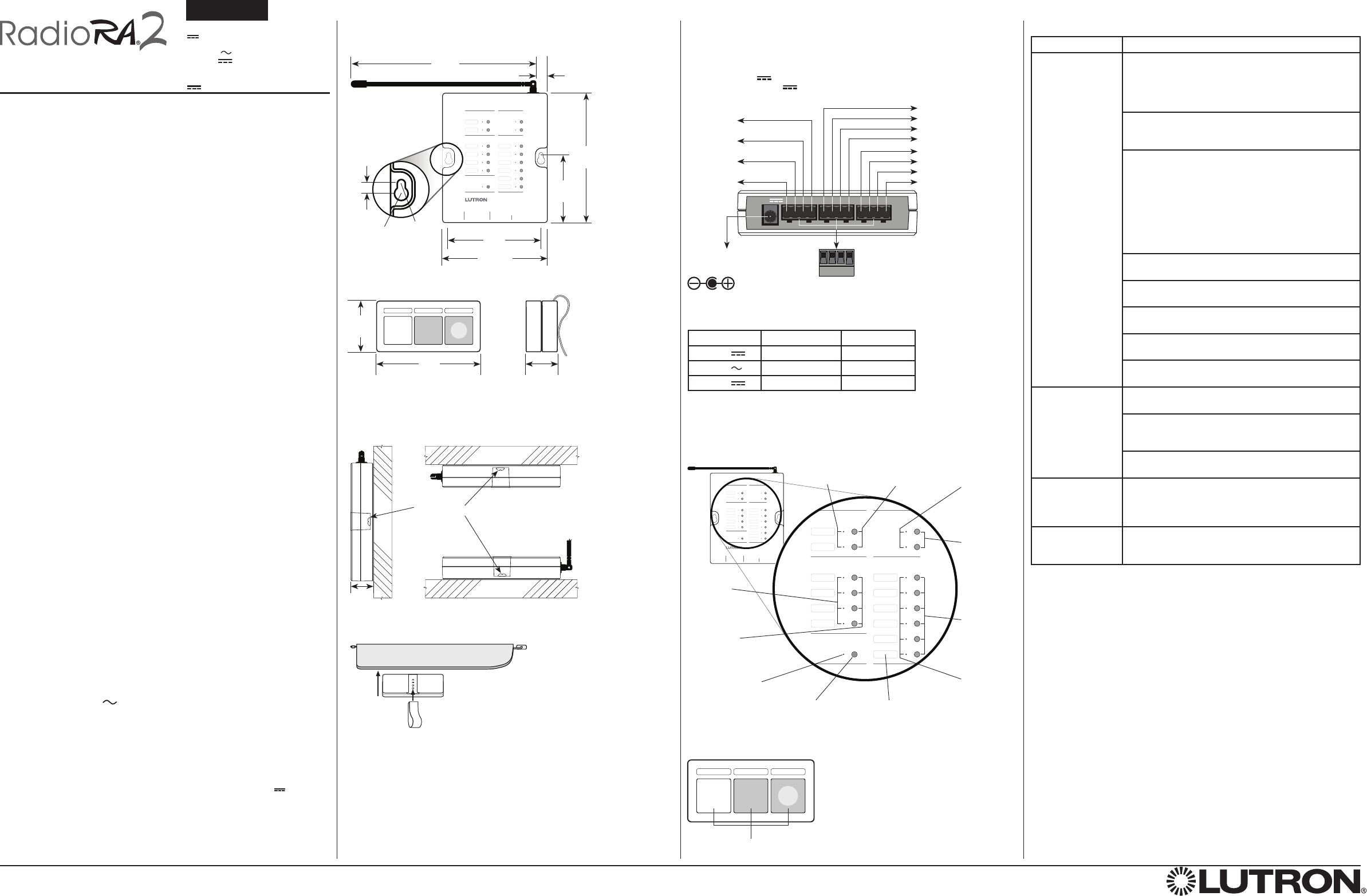
Normal Operation
Dimensions Measurements are in inches (mm).
Installation Instructions
Please Read Before Installing
Lutron Elec tron ics Co., Inc.
7200 Suter Road
Coopersburg, PA 18036-1299
Made and printed in the U.S.A. 8/09 P/N 044-161 Rev. A
English
These products may be covered under one or more of the following U.S. patents: 5,838,226; 5,848,054; 5,905,442; 6,687,487; 6,803,728 and corresponding foreign patents. U.S. and foreign patents may be
pending. Lutron, RadioRA and the sunburst logo are registered trademarks and RadioRA 2 is a trademark of Lutron Electronics Co., Inc.
© 2009 Lutron Electronics Co., Inc.
Warranty: For warranty information, please see the Warranty enclosed with the product, or
visit www.lutron.com/resiinfo.
Connection Diagram Troubleshooting Guide
Output LEDs
Display which
CCOs are active.
Security Input
LEDs
Display which
Security option
has been
selected.
Keypad LEDs
Display status
of lights and
shades / drapes
programmed
to the Keypad
buttons.
Output Buttons
Press to test
CCOs.
6.25
(158.8)
2.72
(70)
5.25
(133.4)
Mounting
hole
detail
0.23
(5.8)
0.31
(7.9)
dia.
0.19
(4.8)
dia.
4.25
(108)
Mounting holes
3.75
(95.3)
0.63
(16)
Visor Control Receiver:
RR-VCRX
9 V 300 mA
DC Adapter: T120-9DC-3
Input: 120 V 60 Hz 6.5 W
Output: 9 V 300 mA
Typical Power Consumption*: 1.6 W
Visor Control Transmitter:
LR-3B-H
3 V 10 mA
Input LEDs
Display which
CCIs are active.
Input Buttons
Press to test CCI
programming.
Keypad Buttons
Press to
test keypad
programing.
Learn Button
Press and hold
for 10 seconds to
enter Learn mode.
Learn LED
Flashes to indicate
that the Receiver is
in Learn mode.
Mounting Diagram
* Typical Power Consumption test conditions: two LEDs on (two presets active), Receiver powered by the 9 V adapter
supplied, no Contact Closure Outputs or Contact Closure Inputs active.
Security Input
Buttons
Press and hold
to test Security
programming.
Visor Control Transmitter Buttons
Press to activate functions remotely.
1.5
(38)
3.19
(81)
0.75
(19)
Transmitter (back view)
Vehicle visor
Receiver (side view)
Receiver (front view)
Transmitter (front view) Transmitter (side view)
Receiver (bottom view)
Contact Closure Outputs (CCO)
Max Voltage / Current: See Relay Contact Ratings below.
Listed Class 2
/
Certified PELV
Minimum Pulse Time: 500 ms
Contact Closure Terminal Blocks
Use Class 2 cable
Maximum 1,000 ft (305 m)
Each terminal holds up to one 16 AWG
(1.0 mm2) or two 18 AWG (0.75 mm2) or
smaller wire.
Visor Control Receiver
Learn
Visor Transmitter
KeypadOutputs
Flash
Full
Security InputInputs
1 2
Power
9V DC
Inputs
C
Full 1 C 2 C
Outputs
3 C 4 C
Flash
Learn
Visor Transmitter
KeypadOutputs
Flash
Full
Security InputInputs
1
-
Output 1
C
-
Common 1
2
-
Output 2
C
-
Common 2
3
-
Output 3
C
-
Common 3
4
-
Output 4
C
-
Common 4
Common - C
Security - Full
Flash
Input 2 - 2
Input 1 - 1
9V
(all inputs)
Visor Control Receiver
Visor Control Transmitter
Contact Closure Inputs (CCI)
ON saturation: <1 V at 2 mA
OFF leakage: <1 µA at 9 V
Minimum Pulse Time: 40 ms
Labels
Place pre-printed
or custom labels in
depression to name
buttons.
Symptom Probable Cause and Action
Dimmers, keypads,
shades/drapes,
security system,
garage doors or
motorized gates do
not respond to the
Visor Control
Receiver or
Transmitter.
Power Not Present
• Ensure that the power supply cord is plugged into a
wall outlet and the power jack on the Receiver.
• Circuit Breaker is OFF or tripped. Reset or turn on
circuit breaker.
System devices are not programmed correctly.
• Program all devices according to the system Setup
Guide.
System devices are not within specified RF range.
• Ensure that dimmers, keypads and shades/drapes are
within 30 ft (9 m) of a repeater.
• Verify that all repeaters are within 60 ft (18 m) of
another repeater.
• Make sure that the Receiver is within 30 ft (9 m) of a
repeater.
• Wait until the Transmitter is within 150 ft (46 m) of the
Receiver before pressing a button on the Transmitter.
Receiver is not programmed correctly.
• See the system Setup Guide to program the Receiver.
Contact Closure Inputs not wired correctly.
• Refer to the Connection Diagram for proper wiring.
The Transmitter is not programmed correctly.
•
See the system Setup Guide to program the Transmitter.
Contact Closure Outputs not wired correctly.
• Refer to the Connection Diagram for proper wiring.
Dead, low, or no batteries in the Transmitter.
• Install new batteries in the Transmitter (CR2032)
The Transmitter is
not communicating
with the Receiver.
The Transmitter is not programmed correctly.
•
See the system Setup Guide to program the Transmitter.
Transmitter is not within specified RF range.
• Wait until the Transmitter is within 150 ft (46 m) of the
Receiver before pressing a button on the Transmitter.
Dead, low, or no batteries in the Transmitter.
• Install new batteries in the Transmitter (CR2032).
LEDs on the
Receiver do not
turn on when it is
powered up.
Improper AC adapter used.
• Use the DC adapter provided with the Receiver.
Top Keypad LED
on the Receiver
flashing rapidly.
Improper adapter used.
• Use the DC adapter provided with the Receiver.
Note: Refer to the system Setup Guide for additional troubleshooting
suggestions.
Voltage Resistive Load Inductive Load
Up to 30 V 1 A 0.2 A
Up to 30 V 1 A 0.1 A
Up to 60 V 0.5 A Do not use.
Relay Contact Ratings