Lutron Electronics 0071 Hybrid Keypad User Manual 1
Lutron Electronics Company Inc Hybrid Keypad 1
Contents
- 1. User Manual 1
- 2. Usre Manual 2
User Manual 1
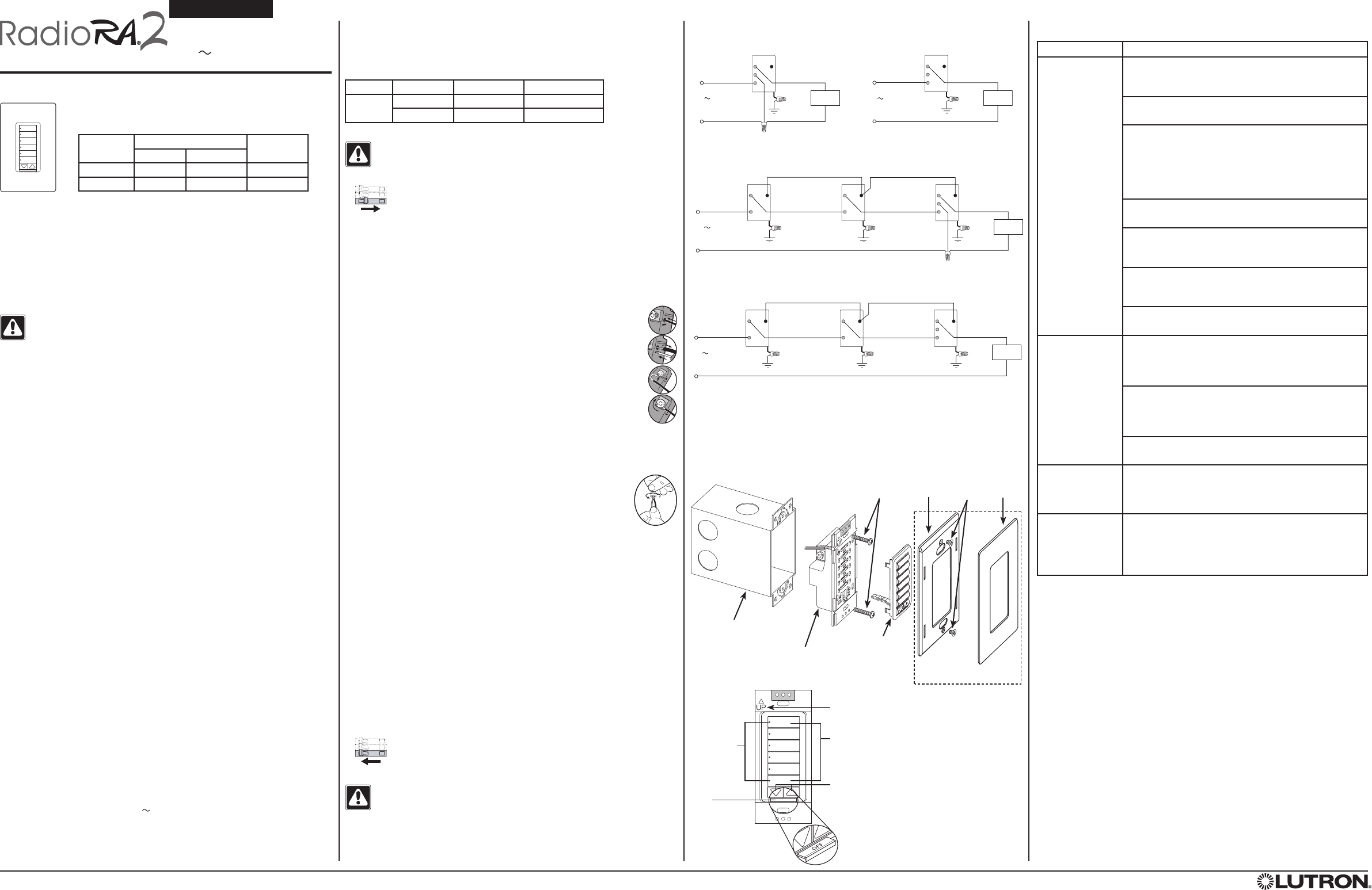
Multi-Location Installation without Neutral2, 3
Brass
Black
Blue
Green
Ground
Lighting
Load
Hybrid Keypad or
Remote Dimmer
Brass
Black
Blue
Green
Ground
Remote Dimmer or
Hybrid Keypad
120 V
50 / 60 Hz
Brass
Black
Blue
Green
Ground
Hot/Live
Neutral
Remote Dimmer or
Hybrid Keypad
Silver
Multi-Location Installation with Neutral3, 4
Brass
Silver
Black
Blue
Green
Ground
Brass
Black
Blue
Green
Ground
Remote Dimmer
120 V
50 / 60 Hz
Brass
Black
Blue
Green
Ground
Hot/Live
Neutral
Remote Dimmer Hybrid Keypad
Wiring Diagram 1b
Lighting
Load
Single Location Installation without Neutral1, 2
Wiring Diagram 2a
Brass
Black
Blue1
Green
Ground
Hot/Live
Neutral
Lighting
Load
Hybrid Keypad
120 V
50 / 60 Hz
Silver
Single Location Installation with Neutral1
Wiring Diagram 1a
120 V
50 / 60 Hz
Brass
Silver
Black
Blue1
Green
Ground
Hot/Live
Neutral
Hybrid Keypad
Lighting
Load
Load Specifications:
1 Load Type: Hybrid Keypads are designed for use with permanently installed incandescent, magnetic
low-voltage, or tungsten halogen only. To reduce the risk of overheating and possible damage to other
equipment, do not install Hybrid Keypads to control receptacles or motor-operated appliances.
2 Low-Voltage Applications: Use Hybrid Keypads with magnetic (core and coil) low-voltage transformers
only. Not for use with electronic (solid-state) low-voltage transformers. Operation of a low-voltage circuit
with lamps inoperative or removed may result in transformer overheating and premature failure. Lutron
strongly recommends the following:
• Do not operate low-voltage circuits without operative lamps in place.
• Replace burned-out lamps as quickly as possible.
• Use transformers that incorporate thermal protection or fused transformer primary windings to
prevent transformer failure due to overcurrent.
Important Notes
WARNING - Entrapment hazard - To avoid the risk of entrapment,
serious injury, or death, these controls must not be used to control
equipment which is not visible from every control location or which
could create hazardous situations such as entrapment if operated accidentally.
Examples of such equipment which must not be operated by these controls
include (but are not limited to) motorized gates, garage doors, industrial doors,
microwave ovens, heating pads, etc. It is the installer’s responsibility to ensure
that the equipment being controlled is visible from every control location and
that only suitable equipment is connected to these controls. Failure to do so
could result in serious injury or death.
Codes: Install in accordance with all local and national electrical codes.
Grounding: When no “grounding means” exist within the wallbox, then the
NEC® 2008, Article 404.9 allows a dimmer without a grounding connection to
be installed as a replacement, as long as a plastic, noncombustible wallplate is
used. For this type of installation, cap or remove the green ground wire on the
Hybrid Keypad and use an appropriate wallplate such as a Lutron® Claro® or
Satin Colors® wallplate.
Neutral Wire: Hybrid Keypads have an available neutral wire terminal that can
be connected to the neutral wire in a wallbox where the Hybrid Keypad is to
be installed. Connecting the neutral wire to a Hybrid Keypad allows a lower
minimum load to be used. Also, normal keypad operation will be available even
if the attached load is not installed or if the lamp is burned out. If a neutral
wire connection is available, connect it to the silver terminal. If a neutral wire
connection is desired but not available in the wallbox, contact a licensed
electrician for installation.
Environment: Ambient operating temperature: 32 °F to 104 °F (0 °C to 40 °C),
0% to 90% humidity, non-condensing. Indoor use only.
Spacing: If mounting one control above another, leave at least 4
½ in (114 mm)
vertical space between them.
Wallplates: Lutron Claro and Satin Colors wallplates are strongly recommended
for best color match and clean aesthetic appearance. Do not paint keypads,
buttons, or wallplates.
Cleaning: To clean, wipe with a clean damp cloth. DO NOT use any chemical
cleaning solutions.
Wallboxes: Lutron recommends using 3
½ in (89 mm) deep wallboxes for easier
installation. Several controls may be installed in one multigang wallbox.
Remote Dimmers: Use only Remote Dimmers (RD-RD) with Hybrid Keypads.
Up to 9 RD-RD controls may be used with a Hybrid keypad.
RF Device Placement: RF dimmers, switches, keypads and shades / draperies
must be located within 30 ft (9 m) of an RF signal repeater. For systems without
an RF signal repeater, all RF dimmers, switches, keypads and shades / draperies
must be located within 30 ft (9 m) of each other. Remote dimmers and switches
are not required to be within a specific range.
Engraving: The Prepaid Engraving Certificate included with the Hybrid
Keypad can be redeemed for a custom engraved replacement kit. To order a
replacement kit please follow the instructions at: www.lutron.com/buttons
Load Type Minimum Load Maximum Load
With Neutral Without Neutral
Incandescent115 W 50 W 450 W
MLV215 W / VA 50 W / VA 350 W / 450 VA
Multigang Installations
In multigang installations, several controls are grouped horizontally in one
multigang wallbox. When combining controls in a wallbox, derating is required;
however, no derating is required for Remote Dimmers.
Derating Chart
Control Load Type End of Gang Middle of Gang
-H6BRL Incandescent 350 W 250 W
MLV 250 W / 350 VA 200 W / 250 VA
Installation
WARNING - Shock hazard - To avoid the risk of electric shock, locate
and remove fuse or lock circuit breaker in the OFF position before
proceeding. Wiring with power ON could result in serious injury or death.
1. Turn power OFF at fusebox or circuit breaker.
2. Check the installation for short circuits before installing control(s). With power
OFF, install standard mechanical switch(es) between Hot and load. Restore
power. If lights do not work or a breaker trips, check wiring. Correct wiring
and check again. Install control(s) only when short is no longer present.
Warranty is void if keypad is installed in a shorted circuit.
3. Wire keypads according to one of the following options:
a. Terminals:
Trim or strip wallbox wires to the length indicated by the strip gauge on the
back of the keypad.
• Push-In Terminals: Use with 14 AWG (1.5 mm2) solid copper wire
only. DO NOT use stranded or twisted wire.
Insert wires fully. To release wire, insert small, flat screwdriver into slot
below push-in terminal. Push screwdriver in while pulling wire out.
OR
• Screw Terminals: use with 12 AWG (2.5 mm2) or 14 AWG (1.5 mm2)
solid copper wire only. DO NOT use stranded or twisted wire.
Wrap wire around screw terminal. Tighten securely to 5 in-lbs (0.55 N•m).
b. Wire Connectors:
Prepare wires. When making wire connections, follow the recommended
strip lengths and combinations for the supplied wire connector.
Note: Wire connector provided is suitable for copper wire only.
Wire Connector:
• Strip insulation 3/8 in (10 mm) for 14 AWG (1.5 mm2)
or 12 AWG (2.5 mm2) wire
• Strip insulation 7/16 in (11 mm) for 18 AWG
(0.75 mm2) wire
• Use to join one or two 14 AWG (1.5 mm2) or 12 AWG
(2.5 mm2) wires with one 18 AWG (0.75 mm2) ground wire.
For installations WITH a neutral wire: See Wiring Diagrams 1a or 1b.
For installations WITHOUT a neutral wire: See Wiring Diagram 2a or 2b.
Note: If a neutral wire connection is available, connect it to the silver terminal.
4. Push all wires back into the wallbox and loosely fasten the Hybrid Keypad to the
wallbox using the control mounting screws provided. Do not pinch the wires.
5. Attach Lutron Claro or Satin Colors wallplate adapter and wallplate. See the
Mounting Diagram.
a. Install the wallplate adapter onto the front of the Hybrid Keypad.
b. Tighten the keypad mounting screws until wallplate adapter is flush to the
wall (do not over-tighten).
c. Snap the wallplate onto the wallplate adapter and verify that the Hybrid
Keypad is aligned properly.
d. If the Hybrid Keypad is misaligned, remove wallplate and loosen the
mounting screws to adjust the Hybrid Keypad appropriately. When the Hybrid
Keypad is alligned properly, snap the wallplate onto the wallplate adapter.
6. Restore power. Check for correct local operation. See Operation.
Installation Instructions
Please Read Before Installing
1 When using controls in single location installations, tighten the blue terminal without any
wires attached. DO NOT connect the blue terminal to any other wiring or to ground.
2 In installations without a neutral wire connection, tighten the silver terminal without any
wires attached. DO NOT connect the silver terminal to any other wiring or to ground.
3 Up to 9 Remote Dimmers may be connected to the Hybrid Keypad. Total blue terminal
wire length may be up to 250 ft (76 m).
4 Neutral wire Hybrid Keypads must be connected on the load side of a multi-location
installation.
Operation
Lamp Replacement
WARNING - Shock hazard - For any procedure other than routine lamp
replacement, power must be disconnected at the main electrical panel.
Working with power ON could result in serious injury or even death.
For routine lamp replacement, remove power from the fixture(s) by pulling the
FASSTM switch out on both the Hybrid Keypad and all Remote Dimmers
Troubleshooting Guide
Lutron Elec tron ics Co., Inc.
7200 Suter Road
Coopersburg, PA 18036-1299
Made and print ed in the U.S.A. 04/10 P/N 044-167 Rev. A
Symptom Probable Cause and Action
Lights do not
respond to a
Hybrid Keypad
button press
or do not go to
desired levels.
Power not present at keypad
• Circuit breaker tripped or OFF. Reset or turn ON
circuit breaker.
The FASS switch is pulled out.
• Push FASS switch in.
Wiring
• Wires shorted. Make sure the blue terminal is not
grounded or shorted to any other wires.
• Wiring error. Wire the Hybrid Keypad according to
the Installation section and the appropriate Wiring
Diagram.
Lamps burned out or not installed
• Replace or install lamps.
Dioded lamps
• If dioded lamps are being used, replace with
non-dioded lamps.
Out of RF range
• Reposition to be within 30 feet (9 m) of an RF signal
repeater.
Improper programming
• Program according to the system Setup Guide.
Attached lights
turn ON when top
Hybrid keypad
button is pressed,
then turn OFF
Wiring
• Wiring error. Wire the Hybrid Keypad according to
the Installation section and the appropriate Wiring
Diagram.
Load is less than minimum load requirement
• Make sure the connected load meets the
appropriate minimum load requirement for that
control. See Load Specifications.
Improper programming
• Program according to the system Setup Guide.
All LEDs on the
Hybrid Keypad
flash when any
button is pressed.
The Hybrid Keypad is in Factory Settings mode and has
not been configured to work in a system.
• Follow the steps in the system Setup Guide to program
the Hybrid Keypad.
Wallplate is warm Solid-state control dissipation
• Solid-state Hybrid Keypads internally dissipate
about 2% of the total connected load. It is normal
for Hybrid Keypads to feel warm to the touch during
operation.
Note: Refer to the system Setup Guide for additional troubleshooting
suggestions.
Returning Hybrid Keypads to Factory Settings
Returning a Hybrid Keypad to its Factory Settings will remove it from the
system and erase all dimmer settings and keypad programming.
Step 1: Triple tap any button (except raise / lower) on the Hybrid Keypad. DO
NOT release after third tap.
Step 2: Keep the button pressed on the third tap until all the status LEDs start
to flash slowly (approximately 3 seconds).
Step 3: Immediately release the button and triple tap the button again. The
status LEDs on the Hybrid Keypad will flash quickly.
The Hybrid Keypad has now been returned to Factory Settings.
Warranty: For warranty information, please see the Warranty enclosed with the
product, or visit www.lutron.com/resiinfo
English
Mounting Diagram
Wallplate adapter and wallplate
purchased separately.
NEC is a registered trademark of the National Fire Protection Association, Quincy, Massachusetts. Lutron, Claro, Satin Colors, RadioRA and the sunburst logo are registered trademarks and RadioRA 2 and FASS are
trademarks of Lutron Electronics Co., Inc.
©2010 Lutron Electronics Co., Inc.
Technical Assistance:
U.S.A. / Canada: 1.800.523.9466
Mexico: +1.888.235.2910
Other Countries: +1.610.282.3800
24 hours a day, 7 days a week.
Use these instructions to install the model number listed above. For
system Setup Guide and tools visit: www.lutron.com/radiora2
Designer-style Hybrid Keypad
RRD-H6BRL
120 V 50 / 60 Hz
Typical Power Consumption*: 0.75 W
* Typical Power Consumption test conditions: load is off, all backlights on medium intensity, two LEDs on
(two presets active), keypad powered at 120 V
Twist wire
connector
tight.
ON
OFF
ON
OFF
ON
OFF
Wiring Diagram 2b
NOTE: Orientation arrow MUST point UP.
Status LEDs
Show which
button
has been
activated. Raise / Lower Buttons
Lights increase / decrease in intensity and
shades / draperies raise / lower.
FASS
Front
Accessible
Service
Switch
Keypad Buttons
Press to activate desired levels of lighting or
positions of shades /draperies.
By default, the internal dimmer is controlled by the
top keypad button. Tap to toggle load ON / OFF.
Replacement
Kit
Keypad
Mounting
Screws
Adapter
Mounting
Screws
Wallplate
Adapter Wallplate
ON
OFF
ON
OFF
ON
OFF
Wallbox
Hybrid
Keypad