Lutron Electronics 0079 Occupancy/Vacancy Sensor User Manual additional
Lutron Electronics Company Inc Occupancy/Vacancy Sensor additional
Contents
- 1. User Manual
- 2. User Manual (additional)
User Manual (additional)
SPECIFICATION SUBMITTAL Page
Job Name:
Job Number:
Model Numbers:
Radio Powr SavrTM Wireless Occupancy and Vacancy Sensors
369432 Rev A 1 04.08.11
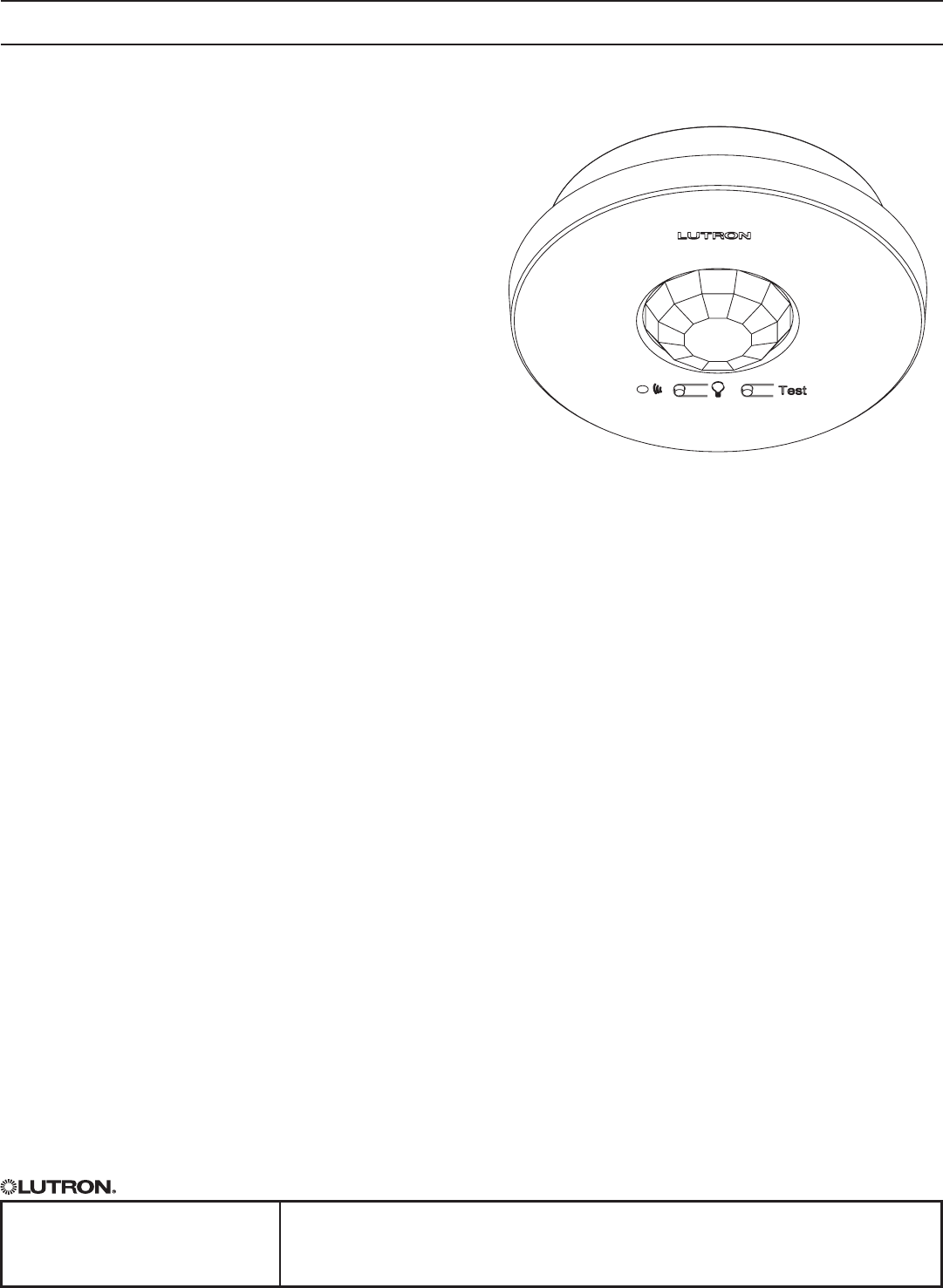
Wireless Ceiling Mount Sensor
Lutron’s ceiling-mounted occupancy/vacancy sensors
are wireless, battery-powered passive infrared (PIR)
sensors that automatically control lights via RF
communication to compatible dimming and switching
devices. These sensors detect the heat from people
moving within an area to determine when the space
is occupied. The sensors then wirelessly transmit the
appropriate commands to the associated dimming
and switching devices to turn the lights on or off
automatically. They combine both convenience
and exceptional energy savings along with ease
of installation.
Features
•Wirelessoccupancysensorhas3settingsavailable:
Auto-On/Auto-Off, Auto-On Low-Light/Auto-Off, and
Manual-On/Auto-Off
•Auto-OnLow-Lightfeaturewillonlyturnlightson
automatically if there is less than approximately 1 fc
(10 lux) of ambient light
•VacancymodelavailabletomeetCATitle24requirements
•10-yearbatterylifedesign
•Passiveinfraredmotiondetectionwithexclusive
LutronXCTTM Technology for fine motion detection
•360˚coveragerangesfrom324sqft(98m()to676sqft
(206m() (depending on mounting height)
•Multipleceiling-mountmethodsavailablefordifferent
ceiling materials
•RoHScompliant
•SimpleandintuitiveadjustmentsavailableforTimeout,
Auto-On, and Activity settings
•Frontaccessibletestbuttonsmakesetupeasy
•Lensilluminatesduringtestmodetoverifyideallocations
•Multiplesensorscanbeaddedforextendedcoverage—
refer to product specification submittal of receiving device
to determine system limits
Compatible RF Devices:
•ForusewithLutron® products only
•CommunicatestothefollowingwirelessLutron
systems:
- Maestro®Wireless®(MRF2)
- GRAFIK Eye®QSWireless
-EnergiSavrNodeTMQS(withQSSensorModule
onQSLink)
- Quantum® (withQSSensorModuleonQSLink)
- RadioRA® 2
-HomeWorks®QS
Models Available:
•LRF2-OCR2B-P-WH*
434 MHz Occupancy/Vacancy Sensor
•LRF2-VCR2B-P-WH*
434 MHz Vacancy Sensor
*WH(white)
SPECIFICATION SUBMITTAL Page
Job Name:
Job Number:
Model Numbers:
Radio Powr SavrTM Wireless Occupancy and Vacancy Sensors
369432 Rev A 2 04.08.11
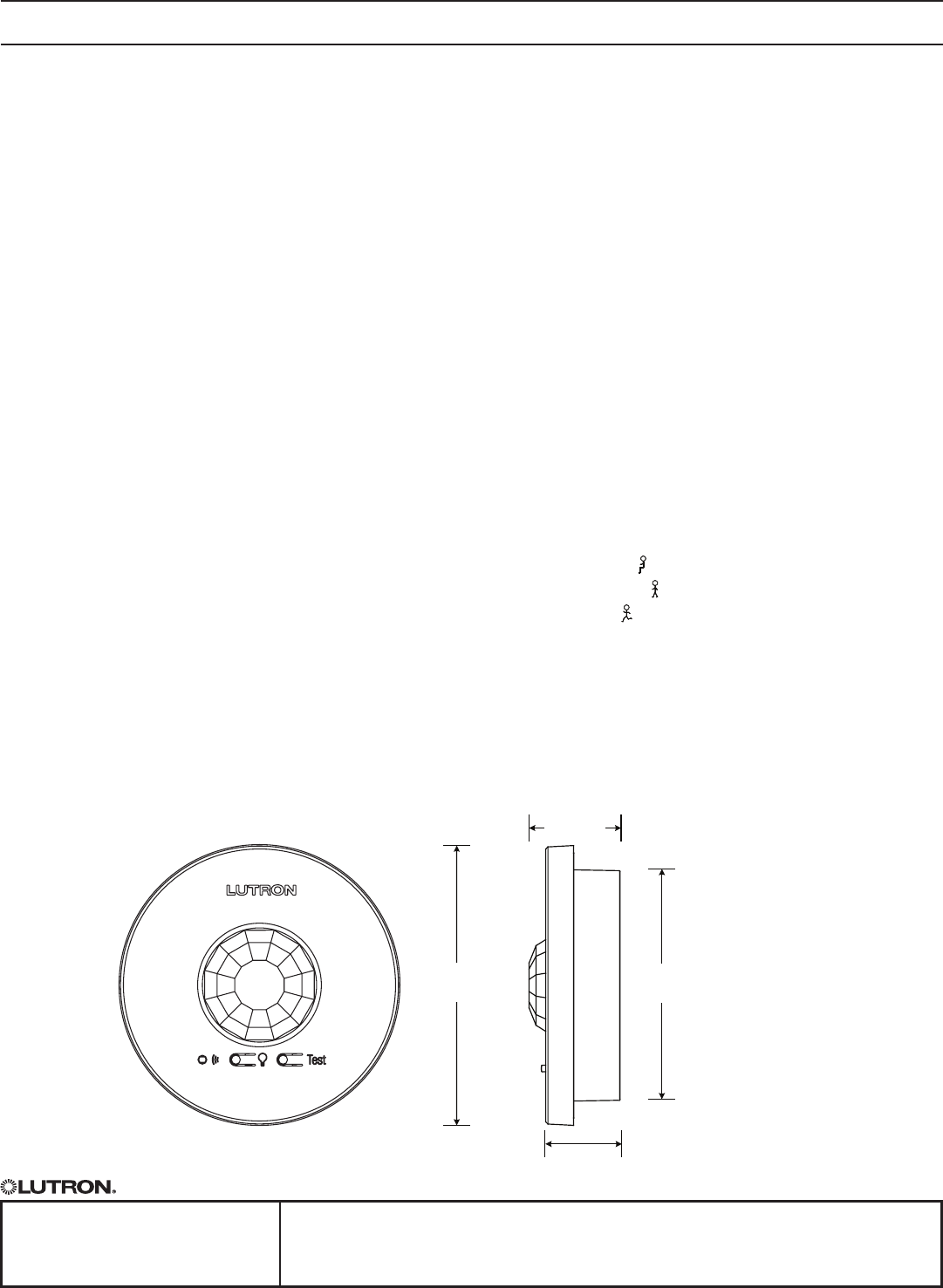
3.57 in
(90.7mm)
1.13 in
(28.7 mm)
0.887 in
(22.5 mm)
2.85 in
(72.4 mm)
Specifications
Standards
•FCCcertied
•ICcertied
•COFETELcertied
•RoHScompliant
Environment
•Temperature:32˚Fto104˚F(0˚Cto40˚C)
•Forindooruseonly
Power
•Operatingvoltage:3V-
•Operatingcurrent:14μAnominal
•RequiresoneCR123lithiumbattery
•10-yearbatterylifedesign
•Non-volatilememory(savedchangesarestored
during power loss)
Sensor Coverage Test
•Frontaccessibletestbutton
•Lensilluminatesorangeinresponsetomotion
duringtestmodeandisvisiblefrom60ft(18m)
Wireless Communication Test
•Frontaccessibletestbutton
•Turnloadsonandoff
Timeout Options
•1minute*
•5minutes
•15minutes**
•30minutes
Auto-On Options (Occupancy Version Only)
•“Always”**-SensorturnslightsONandOFFauto-
matically.
•“Lowlight”-SensorturnslightsONautomatically
onlyinlowambientlightconditions.Sensorturns
lights OFF automatically.
•“Disable”-LightsmustbeturnedONmanuallyfrom
dimmingorswitchingdevice.Sensorturnslights
OFF automatically.
Activity Options
•LowActivity**( )
•MediumActivity( )
•HighActivity( )
**-intendedforuseinhigh-activity,brieyoccupied
areas only
*-defaultsettings
Dimensions
SPECIFICATION SUBMITTAL Page
Job Name:
Job Number:
Model Numbers:
Radio Powr SavrTM Wireless Occupancy and Vacancy Sensors
369432 Rev A 3 04.08.11
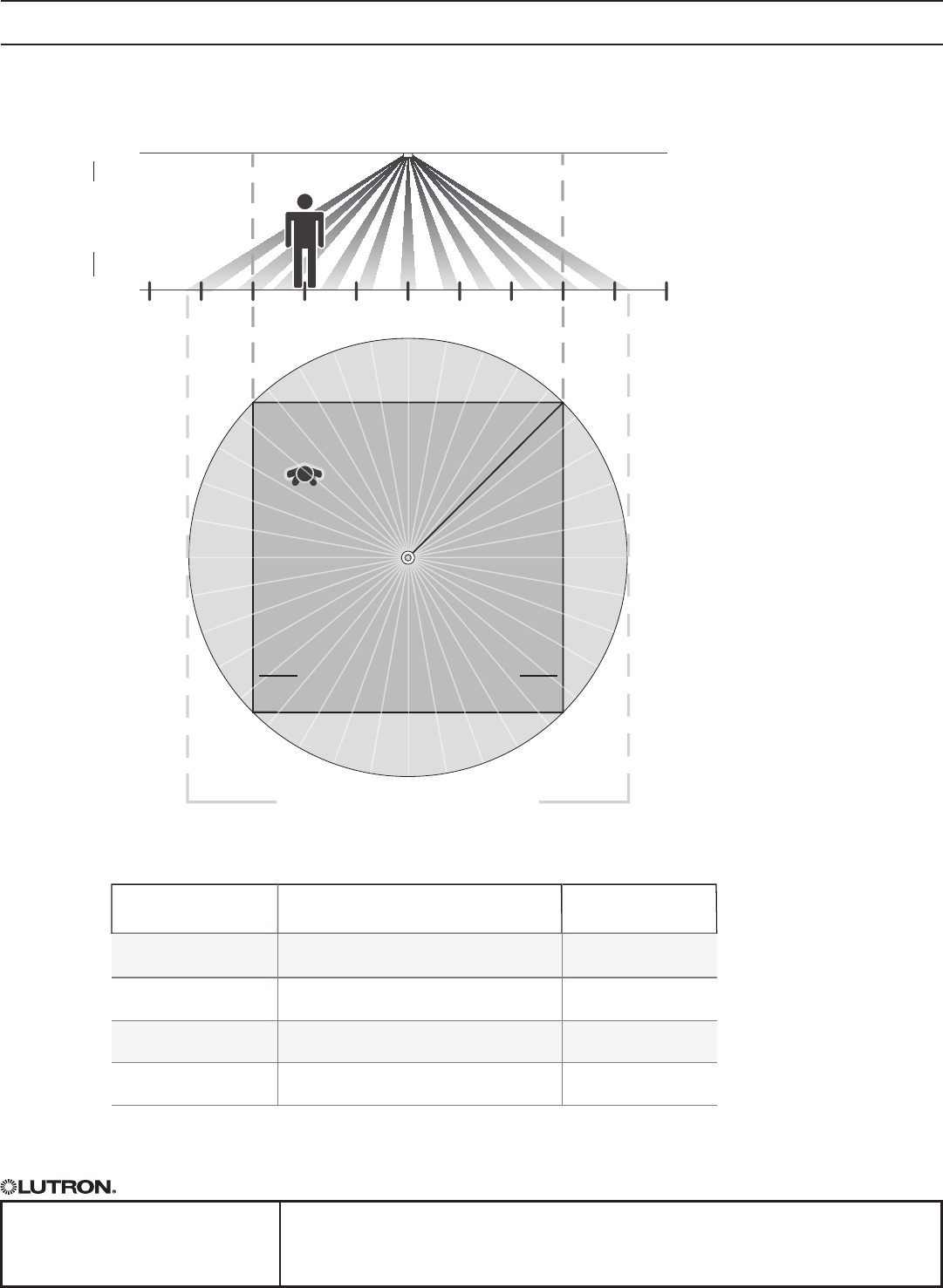
Range Diagrams
Sensor Coverage with an 8 ft (2.4 m) Ceiling
15 ft
(4.6 m)
12 ft
(3.7 m)
9 ft
(2.7 m)
6 ft
(1.8 m)
3 ft
(0.9 m)
0 ft
(0 m)
3 ft
(0.9 m)
6 ft
(1.8 m)
9 ft
(2.7 m)
12 ft
(3.7 m)
15 ft
(4.6 m)
Radius of Coverage at Floor
Sensor
Occupant
18 x 18 ft (5.5 x 5.5 m)
Maximum Room Dimensions
for Complete Coverage when
mounted on an 8 ft (2.4 m) Ceiling
13 ft (4.0 m)
Radius of Coverage at Floor when
mounted on an 8 ft (2.4 m) Ceiling
Ceiling
Floor
8 ft
(2.4 m)
Ceiling
height
Instructions
Sensor Coverage Chart (for sensor mounted in center of room)
Ceiling height
Maximum room dimensions
for complete floor coverage Square feet
8 ft (2.4 m) 18 × 18 ft (5.5 × 5.5 m) 324 ft2 (30.2 m2)
9 ft (2.7 m) 20 × 20 ft (6.1 × 6.1 m) 400 ft2 (37.2 m2)
10 ft (3.0 m) 22 × 22 ft (6.7 × 6.7 m) 484 ft2 (44.9 m2)
12 ft (3.7 m) 26 × 26 ft (7.9 × 7.9 m) 676 ft2 (62.4 m2)
*Multiplesensorscanbeaddedforextendedcoverage—refer to product specification
submittal of receiving device to determine system limits.

SPECIFICATION SUBMITTAL Page
Job Name:
Job Number:
Model Numbers:
Radio Powr SavrTM Wireless Occupancy and Vacancy Sensors
369432 Rev A 4 04.08.11
Installation Overview
Sensor Placement
•Thesensor’sabilitytodetectmotionrequireslineofsightofroomoccupants.Thesensormusthaveanunob-
structed view of the room. DO NOT mount behind or near tall cabinets, shelves, hanging fixtures, ceiling fans,
etc.Thesensorcannotseethroughglassobjectssuchaspatioorshowerdoors.
•Hotobjectsandmovingaircurrentscanaffectthesensor’sperformance.Toensureproperoperation,thesen-
sorshouldbemountedatleast4ft(1.2m)awayfromlightbulbsbelowtheceilinglineandHVACvents.
•Thesensor’sperformancedependsonatemperaturedifferentialbetweentheambientroomtemperatureand
thatofroomoccupants.Warmerroomsmayreducethesensor’sabilitytodetectoccupants.
•Thesensorshouldbemountedwithin60ft(18m)lineofsightor30ft(9.1m)throughwalls,oftheassociated
dimming and switching receiving devices.
Mounting
•MountingofanyRFdevicesonorincloseproximitytoametalsurface(e.g.directlyonxturewithmetalhousing,
metal-backedceilingtile)willdrasticallyreducetheeffectiverangeofradiosignaltransmissionorreception.
•AllRFdevicesmustbemountedonnon-conductivematerialstoensureproperperformance.
Temporary mounting is recommended to test sensor coverage and wireless communication before permanently
installing the sensor.
Drop Ceiling (Compressed Fiber Ceiling Tile)
•Theceilingtilemountingwireisprovidedforbothtemporaryandpermanentmountingofthesensortoceiling
tiles. It is designed to allow temporary mounting, testing, and repositioning (if necessary) of the sensor without
damaging a ceiling tile. Once the sensor’s final position has been chosen, the mounting wire should be twisted
tolockthesensorinplacepermanently.
Solid Ceiling (Drywall, Plaster, Concrete, or Wood)
•Temporarymounting:Onedouble-sidedadhesivestripisprovidedfortemporarilymountingandtesting
the sensor.
•Permanentmounting:Screwsandanchors(fordrywallorplaster)providedtomountsensor.
Recess Mount
•Ceilingmountclampsinternallytoceilingtile.Sensortwist-locksintomount,sitsushwithceiling(asshownbelow)
•Openingis3"indiameter
•Purchasedasaseparatekit:LRF-CRMK-WH
Installing the Ceiling Mount Adapter
Cut mounting hole
Cut a 3 in to 3 in (76 mm to 76 mm) diameter hole to insert the ceiling
mount adapter.
Instalación del adaptador de montaje en cielo raso
Corte un orifi cio de montaje
Corte un orifi cio de 76 mm a 76 mm (3 pulg. a 3 pulg.) de diámetro para
insertar el adaptador de montaje en cielo raso.
Insert ceiling mount adapter
Insert the ceiling mount adapter into the hole and rotate brackets outwards by
turning screws.
Inserte el adaptador de montaje en cielo raso
Inserte el adaptador de montaje en cielo raso en el orifi cio y gire los soportes
hacia afuera apretando los tornillos.
1 1
2 2
3 in to 3 in
(76 mm to 76 mm)
76 mm to 76 mm
(3 in to 3 in)
Note: No need
to access top
of ceiling.
Nota: No se
requiere acceso
a la parte su-
perior del cielo
raso.
Clamp adapter to ceiling
Using a Philips screwdriver, hand-tighten the brackets, clamping the adapter to
the ceiling. Do not overtighten.
Fije el adaptador al cielo raso
Utilice un destornillador Phillips para ajustar a mano los soportes y fi jar el
adaptador al cielo raso. No ajuste demasiado.
3 3
®
Installation English Instalación Español
SPECIFICATION SUBMITTAL Page
Job Name:
Job Number:
Model Numbers:
Radio Powr SavrTM Wireless Occupancy and Vacancy Sensors
369432 Rev A 5 04.08.11
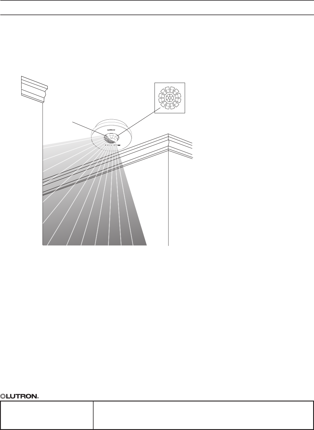
Lens Masking
Wheneverpossible,thesensorshouldbeinstalledinalocationwhereitcannoteasilyseeintoareasoutsidethe
intendedspace,suchashallwaysoradjacentrooms.Ifthissituationcannotbeavoided,portionsofthelens
maybemaskedwiththeprovidedlabelstoblockthesensor’sviewoftheundesiredareas.
Lens sections
shown in white
aremaskedwith
labels
Lens sections
shown in gray
have not been
masked
Lens label
maskingsheet