Lutron Electronics 0096 Relay Module User Manual Manual 1
Lutron Electronics Company Inc Relay Module Manual 1
Contents
- 1. Manual 1
- 2. Manual 2
Manual 1
Lutron Electronics Co., Inc. | 7200 Suter Road
Coopersburg, PA 18036-1299, U.S.A.
RF CCO Module | Installation
041424
Rev. A
05/2013
Important Notes: Please read before installing.
• For installation by a qualified electrician in accordance
with all local and national electrical codes.
• Note: Use copper conductors only.
• Check to see that the device type and rating is suitable
for the application.
• DONOT install if product has any visible damage.
• If moisture or condensation is evident, allow the product
to dry completely before installation.
• Operate between 32 °F to 131 °F (0 °C to 55 °C).
• 0% to 90% humidity, non-condensing.
• For indoor use only.
• 24V~or24V- supply and load shall be protected
via an approved power source in accordance with IEC/
EN61558-2(SELVsupply).
LMJ-CCO1-24-B 24V~45mA
24V-35mA
FCC Information: (LMJ- model only)
This device complies with part 15 of the FCC Rules and
Industry Canada licence-exempt RSS standard(s). Operation is
subject to the following two conditions:
(1) This device may not cause interference, and
(2) this device must accept any interference, including
interference that may cause undesired operation.
Modifications not expressly approved by Lutron Electronics Co.,
Inc. could void the user’s authority to operate this equipment.
NOTE:This equipment has been tested and found to comply
with the limits for a Class B digital device, pursuant to part
15 of the FCC Rules. These limits are designed to provide
reasonable protection against harmful interference in a residential
installation. This equipment generates, uses and can radiate radio
frequency energy and, if not installed and used in accordance
with the instructions, may cause harmful interference to radio
communications. However, there is no guarantee that interference
will not occur in a particular installation. If this equipment does
cause harmful interference to radio or television reception, which
can be determined by turning the equipment off and on, the
user is encouraged to try to correct the interference by one or
more of the following measures:
•Reorientorrelocatethereceivingantenna.
•Increasetheseparationbetweentheequipmentandreceiver.
•Connecttheequipmentintoanoutletonacircuitdifferentfrom
that to which the receiver is connected.
Warranty:
For warranty information, please visit
www.lutron.com/TechnicalDocumentLibrary/Warranty.pdf
www.lutron.com/TechnicalDocumentLibrary/Intl_Warranty.pdf
Lutron and are registered trademarks of Lutron Electronics
Co., Inc.
©2013 Lutron Electronics Co., Inc.
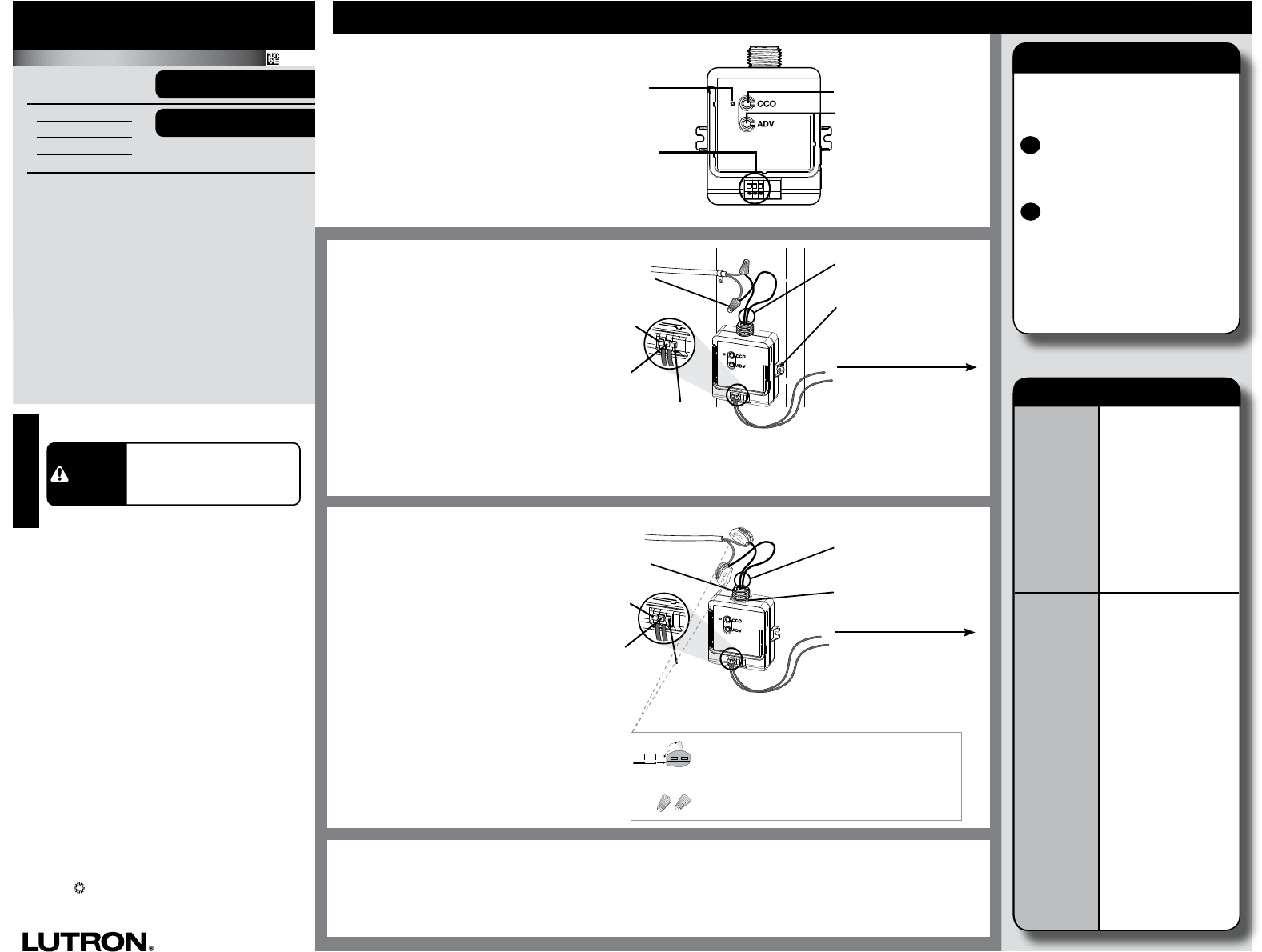
CCO
Status
LED
CCO Toggle
Advanced
Operations
For System Setup Guide and tools
visit www.lutron.com
RFCCOModule
RF CCO Module Operation Reset Factory Defaults
Note: In some instances it may be
necessary to reset the RF CCO
Module back to factory default
settings.
ATriple-taptheAdvancedOperations
(“ADV”)button,ontheRFCCO
ModuleandholduntiltheLED
beginstoashslowly.
Within3secondsofashing,
releaseandtriple-tapthebutton
againandtheLEDwillash
rapidlyindicatingthattheunithas
beenresettofactorydefaults.
B
Note: Any associations or programming
previously set up with the unit will
be lost and will need to be
re-programmed.
CCO-
controlled
device does
not respond
to Wireless
Transmitter(s).
•Ensure power to the RF
CCO Module is properly
applied.
•Ensure the CCO-
controlled device has
been properly wired to
the RF CCO Module.
•Ensure RF CCO module
has been activated in
the system.
•Ensure that the Wireless
Transmitter battery is
installed correctly.
RFCCO
Module does
not respond
toakeypad,
wireless
controller or
sensor.
•Improper programming.
Program from system
programming software.
•Out of RF Range.
Reposition to be within
30 ft (9 m) of an RF
signal repeater.
•Already at current level.
The RF CCO Module
has already responded
to a command, or is
already at the requested
setting.
•Wireless controller or
sensor batteries low or
installed incorrectly.
Replace or install
batteries properly.
•RF interference.
Do not run RF CCO
Module wires with
other power wires or
communication wires
(e.g., networking, audio,
or video signals).
Troubleshooting
English
WheninstallingaRFCCOModule,
wirethemoduleasshown.
Note: RF CCO Module may also be
mounted on or inside a junction box.
If installing unit inside a junction box please
seeApplicationNote#423.
For more information:
www.lutron.com
Installation:
LMJ-, LMM-, LMQ- models
TheRFCCOModuleshouldbe
installedusingthemountingtabs
ontheenclosure(screwsnot
provided).TheRFCCOModule
canbeinstalledinajunction
boxormarshallingbox(optional)
usingtheconduitnut(provided)
orwithmountingscrews(not
provided). Please consult local and
national electric codes for proper
installation.
RF CCO Module Placement
RFCCOModulesmustbelocatedwithin30ft(9m)ofanRFsignalrepeater.RFCCOmodulescannotbe
controlledbythesystemuntiltheyareprogrammedusingthesystemprogrammingsoftware.
Shock Hazard. May result in
serious injury or death.
Turn off power at circuit breaker
before installing the unit.
WARNING
Installation:
LMK- and LMN- models
NECRClass2
LMK-CCO1-24-B
LMN-CCO1-24-B
LMM-CCO1-24-B
LMQ-CCO1-24-B
24V~45mA
24V-35mA SELV
Contact
Closure
Output
(CCO)
24V~or24V-
NO
(Normally Open)
NC
(Normally Closed)
COM
(Common)
Note: When wiring CCO output,
use 20 AWG to 16 AWG
(0.5 mm2 to 1.5 mm2) solid or
stranded wire.
ToCCO-controlleddevice.
Note: CCO Module supply
wires can be connected in
any polarity.
Mountingscrew
(2 Supplied)
Wire Nut
(2 Supplied)
24V~or24V-
NO
(Normally Open)
NC
(Normally Closed)
COM
(Common)
Note: When wiring CCO output,
use 0.5 mm2 to 1.5 mm2 (20 AWG
to 16 AWG) solid or stranded wire.
ToCCO-controlleddevice.
Note: CCO Module supply
wires can be connected in
any polarity.
Conduit Nut
21mm
knockout
opening
For LMN-CCO-24-Buse supplied Twist-on wire
connectors. (2 supplied)
1
2
3
10 mm
WiringaLeverOperatedConnector(shown)
When wiring lever operated connectors (2 supplied)
please use 2.5 mm2to4.0mm2(14AWGto12AWG)
diameter solid or stranded copper wire.
Technical Assistance | 1.800.523.9466 USA, Canada, and the Caribbean | +44.(0)20.7702.0657 Europe | +1.610.282.3800 Others | www.lutron.com