Lutron Electronics 0097 Wirless Lighting Controller User Manual
Lutron Electronics Company Inc Wirless Lighting Controller
User Manual
LUTRON
Control Unit Quick Installation
and Operation Guide
®
Please Read
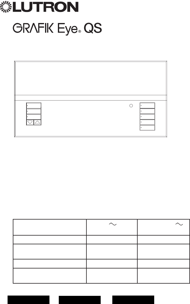
The GRAFIK Eye® QS control unit allows for control
of both lights and shades, without interfaces, using
a single control unit. Features include pushbutton
scene recall, info screen that displays energy savings
and status, IR receiver, astronomic timeclock, contact
closure input, and engravable backlit buttons that are
easy to find and operate.
Model Numbers: QSGRJ-3P, QSGRJ-4P, QSGRJ-6P
QSGR-3P, QSGR-4P, QSGR-6P
120 V
50/60 Hz 220 - 240 V
50/60 Hz
Unit Capacity (watts) 2000 W 3000 W
MLV 2000 VA
1600 W 3000 VA
2400 W
Zone Capacity (watts) 25 – 800 W 40 – 1200 W
MLV 25 – 800 VA
25 – 600 W 40 – 1200 VA
40 – 960 W
See page 6 for IEC PELV/NEC® Class 2 ratings.
For California residents only:
The batteries in these devices contain
Perchlorate Material – special handling may apply.
For more information visit
www.dtsc.ca.gov/hazardouswaste/perchlorate
Contents
Features and Functions of the
GRAFIK Eye® QS Control Unit .................2
Wiring the GRAFIK Eye® QS Control Unit
Overview of Line Voltage/Mains Wiring . . . . . . . . . 3
Line Voltage Wiring Details. . . . . . . . . . . . . . . . . . . 4
Overview of IEC PELV/NEC® Class 2 Wiring . . . . . 6
QS Link Control Wiring Details. . . . . . . . . . . . . . . . 7
Power Group Wiring Example . . . . . . . . . . . . . . . .8
Completing Installation of the
GRAFIK Eye® QS Control Unit . . . . . . . . . . . . . 9
Programming Mode
Entering and Exiting Programming Mode . . . . . . 10
Navigating Menus in Programming Mode . . . . . . 10
Wireless Mode.........................11
FCC Information ..........................11
Zone Setup
Assigning Load Types. . . . . . . . . . . . . . . . . . . . . . 12
Assigning Non-Dim Load Type. . . . . . . . . . . . . . . 12
Setting Load Types........................13
Scene Setup
Setting Zone Levels, Fade Rates,
and Shade Group Actions . . . . . . . . . . . . . . . . . 14
Occupancy Sensor Setup. . . . . . . . . . . . . . . . 15
Scene Mode .............................16
Configuring Occupancy Sensor Settings
(optional) ...............................17
Pico® Wireless Control Setup:
Associating with a GRAFIK Eye® QS
Wireless Control Unit . . . . . . . . . . . . . . . . . . . . . 18
Troubleshooting .......................19
Warranty .............................20
Contact Information . . . . . . . . . . . . . . . . . . . . 20
For additional features and advanced functions,
see the complete installation and operation guide at
www.lutron.com/qs
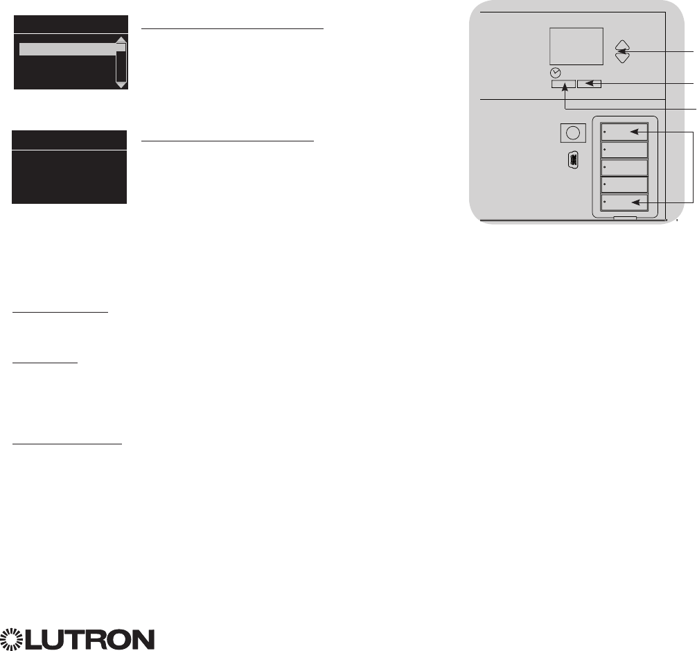
English Español Français
OK
®
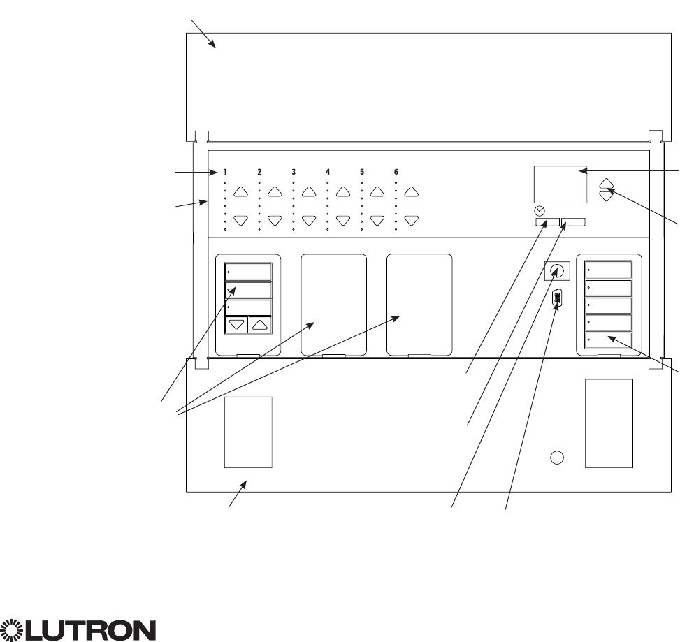
Info screen
Displays status or
programming functions
Scene buttons
With integral scene
indicator LEDs
Optional Shade
button groups
Preset and raise/lower
buttons with integral LEDs
(maximum of 3 button
groups)
Zone numbers
Zone raise/lower buttons
Zone LEDs display current
lighting zone levels
Timeclock button
Displays current
timeclock info
OK button
Used for programming
Infrared receiver
For handheld remote use
Master buttons
Temporarily raise and lower
lighting levels on unit
USB type mini B
For programming via PC
{
Hinged faceplate
Hinged faceplate
Features and Functions of the GRAFIK Eye® QS Control Unit
For additional information, see the complete installation and operation guide at www.lutron.com/qs
GRAFIK Eye® QS Control Unit Quick Installation and Operation Guide 2
®
For additional information, see the complete installation and operation guide at www.lutron.com/qs
GRAFIK Eye® QS Control Unit Quick Installation and Operation Guide 3
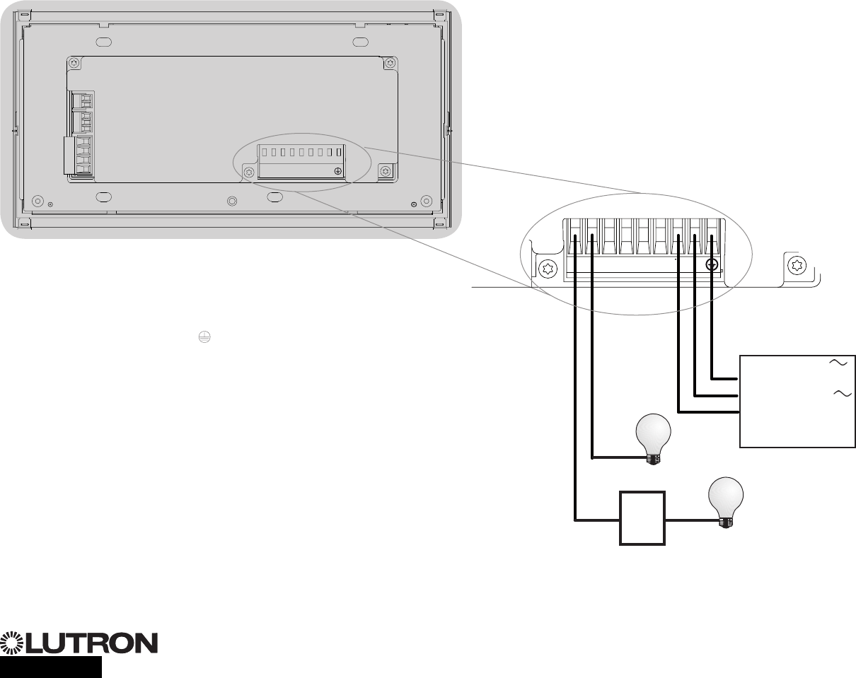
Wiring the GRAFIK Eye® QS Control Unit:
Overview of Line Voltage/Mains Wiring
1234
1 2 ABC
123456LN
12 AWG (4.0 mm2)
each terminal
120 - 127 V
or
220 - 240 V
Distribution
Panel
Line Voltage/Mains
Cables and Load Wiring
123456LN
Incandescent load
Load controlled
by power module
or interface
Terminal labels:
L: Hot/Live
N: Neutral
: Ground
1-6: Dimmed/Switched
line voltage outputs
Power module or
interface
®
Wiring the GRAFIK Eye® QS Control Unit:
Line Voltage Wiring Details
• Useproperlycertifiedcableforallline
voltage/mains cables.
• Propershort-circuitandoverload
protection must be provided at the
distribution panel. You can use up to a
20 A circuit breaker for your installation.
• Installinaccordancewithalllocaland
national electrical codes.
• IECPELV/NEC® Class 2 terminals may
be temporarily unplugged for ease of IR,
occupancy sensor, and control wiring.
•Notice: Risk of damage to unit. Do not
connect line voltage/mains cable to IEC
PELV/NEC® Class 2 terminals.
Step 1: Install wallbox. Mount a 3½ in
(89 mm) deep 4-gang U.S. wallbox on a
dry, flat indoor surface that is accessible
and allows for system programming and
operation. Allow at least 4½ in (110 mm)
clearance above and below the faceplate
to ensure proper heat dissipation. Allow
1 in (25 mm) for faceplate overhang on
all sides.
Note: 4-gang wallbox available from
Lutron;P/N241400.
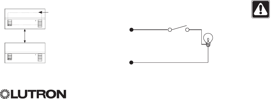
Step 2: Test load wiring.
• TurnpowerOFFatthecircuitbreakeror
fuse box.
• Connectastandardlightswitchbetween
the live lead and load wire to test the
circuit.
• TurnpowerONandcheckforshortor
open circuits. If load does not operate,
the circuit is open. If the circuit breaker
trips (fuse blows or opens), a load short
may exist. Correct short or open circuits
and test again.
Step 3: Check control unit wiring.
•Earth/ground terminal connection must
be made as shown in line voltage wiring
diagrams.
•Do not mix different load types on the
same zone.
•Follow all local and national electrical
codes when installing IEC PELV/
NEC® Class 2 wiring with line voltage/
mains wiring.
WARNING! Shock hazard. May
result in serious injury or death.
Always turn off circuit breaker or
remove main fuse from power line
before doing any work. Before
connecting the loads to the
GRAFIK Eye® QS control unit, test
the loads for short-circuits.
Neutral
Hot/Live Switch
Load
LUTRON
LUTRON
Faceplate overhangs
wallbox on all sides;
allow 1 in (25 mm)
4` in
(110 mm)
For additional information, see the complete installation and operation guide at www.lutron.com/qs
GRAFIK Eye® QS Control Unit Quick Installation and Operation Guide 4

®
For additional information, see the complete installation and operation guide at www.lutron.com/qs
GRAFIK Eye® QS Control Unit Quick Installation and Operation Guide 5
Wiring the GRAFIK Eye® QS Control Unit:
Line Voltage Wiring Details (continued)
Step 4: Connect line voltage and loads
to control unit.
• Strip9 in (8 mm) of insulation off the line
voltage/mains cables in the wallbox.
• Connectthelinevoltage/mains,ground,
and load wires to the appropriate
terminals on the back of the control unit.
L: Hot/Live
N:Neutral
: Ground
Terminals 1-6: Dimmed/Switched
line voltage outputs
9 in
(8 mm)
The recommended installation torque is
5.0 in∙lb(0.6N∙m) for line voltage/mains
connections and 5.0 in∙lb(0.6N∙m) for
the earth/ground connection.
Note: See the zone setup section for a
list of compatible load types and
instructions for programming the
GRAFIK Eye® QS control unit to
properly recognize them.
Notice: Risk of damage to unit. GRAFIK Eye® QS control units must be in stalled by a
qual i fied electrician in accordance with all applica ble reg u la tions and building codes.
Im prop er wiring can result in dam age to control units or oth er equipment.
Note: To avoid over heat ing and pos si ble damage to equipment, do not install control
units to dim re cep ta cles, mo tor-op erated ap pli ances, or flu o res cent lighting not
equipped with Lutron Hi-lume®, Eco-10®, Tu-Wire®, electron ic dim ming ballasts, or
other devices approved for your location. In dimmed mag net ic low-voltage cir cuits,
you can pre vent trans former overheating and failure by avoid ing excessively high cur-
rent flow. Do not op erate control units with any lamps re moved or burned out; re place
any burned out lamps imme di ate ly; use only transform ers that in cor po rate ther mal
pro tection or fused pri ma ry wind ings. Control units are de signed for res i den tial and
commercial use, for indoor use only.
1234
1 2 ABC
123456LN
Contact Closure Input Wiring
24 V 50 mA
For settings, see the full installation
and operation guide at
www.lutron.com/qs.
®
1 2 ABC
NH123456
1234
1234
1 2
ABC
123456LN
1234
1 2
ABC
123456LN
Note: Use appropriate wire connecting
devices as specified by local
codes.
Example:
Occupancy sensor
(maximum 1)
1: COM
2: 24 V *
3: MUX
4: MUX
QS Link Control Wiring
24 V 100 mA
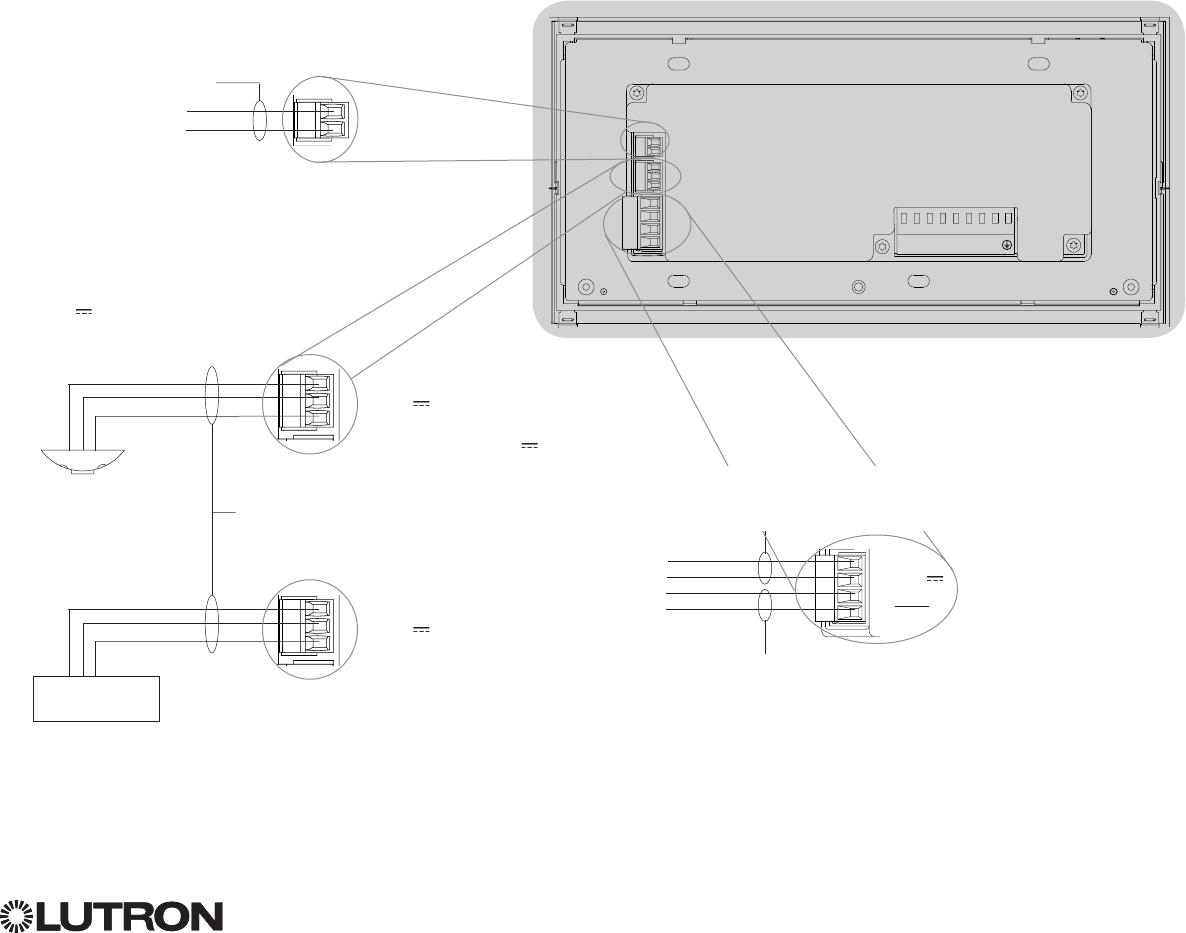
Wiring the GRAFIK Eye® QS Control Unit:
Overview of IEC PELV/NEC® Class 2 Wiring
IR Wiring
From external
IR connection
(by others)
18 AWG (1.0 mm2)
each terminal
18 AWG (1.0 mm2)
each terminal
1: IR DATA
2: IR COM
A: CCI SIG
B: 24 V
C: CCI COM
To control stations,
shades, or other
GRAFIK Eye® QS
control units
Data (terminals 3 and 4):
Twisted, shielded pair 22 AWG (0.5 mm2)
each terminal
Common and power (terminals 1 and 2):
Two 18 AWG (1.0 mm2) each terminal (for link <500 ft/153 m)
Two 12 AWG (4.0 mm2) each terminal (for link 500-2000 ft/153-610 m)
* Do not connect terminal 2
between any GRAFIK Eye® QS
control unit and any other power
supply, including another GRAFIK
Eye® QS control unit.
See “Power Group Wiring” for a
detailed wiring example.
1234
1 2
ABC
123456LN
Example:
Emergency lighting interface (maximum 1)
Note: The GRAFIK Eye® QS control unit
mustbepoweredbyaNormal/
Emergency distribution panel for
proper ELI operation. Refer to the
LUT-ELI-3PH Installation Guide for
the complete wiring diagram.
A: CCI SIG
B: 24 V
C: CCI COM
LUT-ELI-3PH
Signal
+V Input
Circuit Common
For additional information, see the complete installation and operation guide at www.lutron.com/qs
GRAFIK Eye® QS Control Unit Quick Installation and Operation Guide 6
• SystemcommunicationusesIECPELV/NEC®
Class 2 wiring.
• Followalllocalandnationalelectricalcodeswhen
installingIECPELV/NEC® Class 2 wiring with line
voltage/mains wiring.
• Eachterminalacceptsuptotwo18AWG(1.0mm2)
wires.
• Totallengthofcontrollinkmustnotexceed
2000 ft (610 m).
• Makeallconnectionsinthecontrolunit’swallbox.
• WiringcanbeT-tappedordaisy-chained.
• IECPELV/NEC® Class 2 24 V 150 mA.
System Limits
The QS wired communication link is limited to 100
devices or 100 zones.
The GRAFIK Eye® QS control unit supplies 3 Power
Draw Units (PDUs) on the QS link. Refer to the
QS Link Power Draw Units specification submittal
(LutronPN369405)formoreinformationconcerning
Power Draw Units.
®
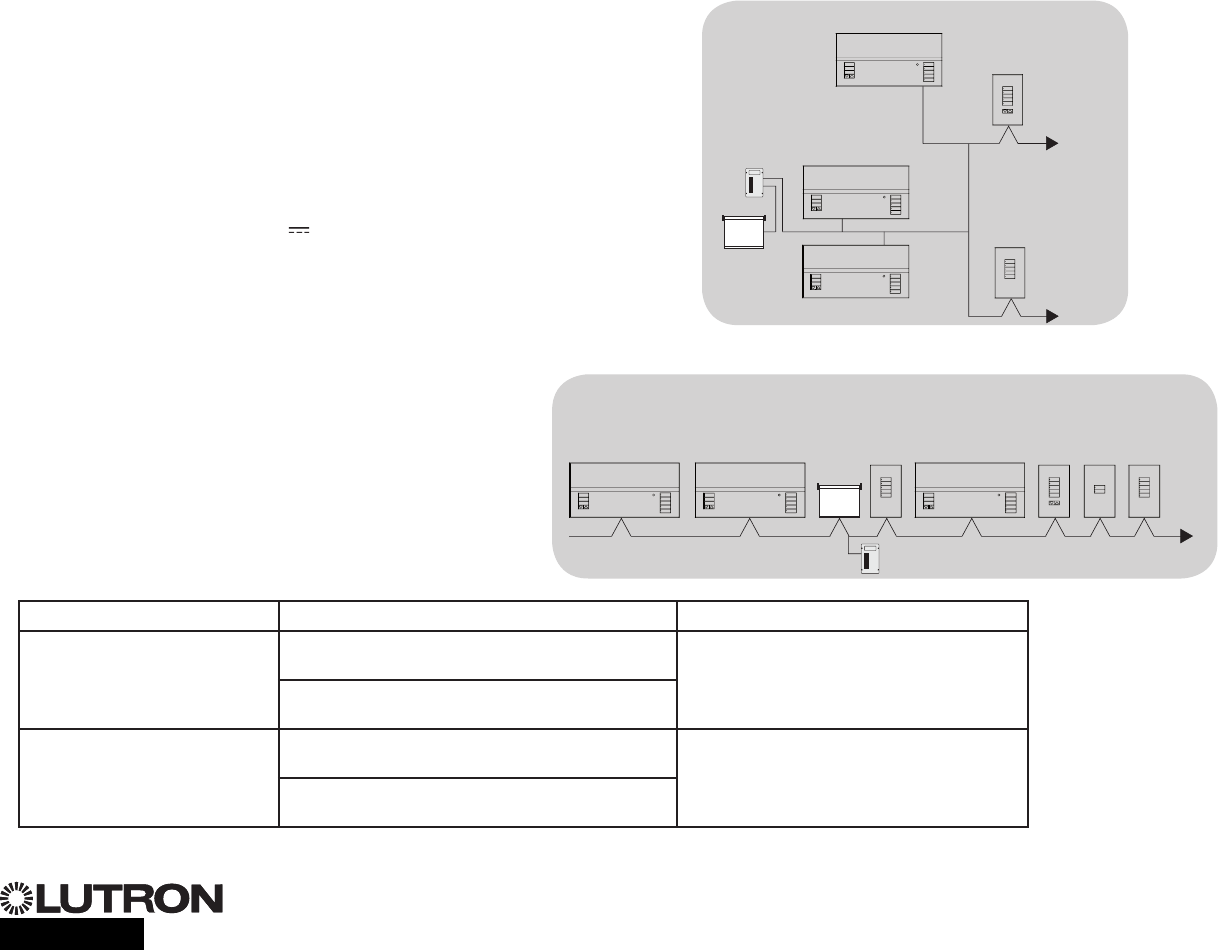
Wiring the GRAFIK Eye® QS Control Unit:
QS Link Control Wiring Details
QS smart
power
panel
LUTRON
LUTRON
LUTRON
LUTRONLUTRON
LUTRON
LUTRON
LUTRON
LUTRON
LUTRON
LUTRON
LUTRON
T-Tap Wiring Example
GRAFIK Eye® QS
control unit
Sivoia® QS
shade/drape
seeTouch® QS
wallstation
LUTRON
LUTRON
LUTRON
LUTRONLUTRON
LUTRON
LUTRON
LUTRON
LUTRON
LUTRON
LUTRON LUTRON LUTRON
LUTRON
GRAFIK Eye® QS
control unit
Sivoia®
QS
shade/
drape
seeTouch® QS
wallstations
Daisy-Chain Wiring Example
QS smart
power panel
GRAFIK Eye® QS
control unit
For additional information, see the complete installation and operation guide at www.lutron.com/qs
GRAFIK Eye® QS Control Unit Quick Installation and Operation Guide 7
Wire Sizes (check compatibility in your area)
QS Link Wiring Length Wire Gauge Lutron Cable Part Number
Less than 500 ft (153 m) Power (terminals 1 and 2)
1 pair 18 AWG (1.0 mm2) GRX-CBL-346S (non-plenum)
GRX-PCBL-346S (plenum)
Data (terminals 3 and 4)
1 twisted, shielded pair 22 AWG (0.5 mm2)
500 to 2 000 ft
(153 to 610 m) Power (terminals 1 and 2)
1 pair 12 AWG (4.0 mm2) GRX-CBL-46L (non-plenum)
GRX-PCBL-46L (plenum)
Data (terminals 3 and 4)
1 twisted, shielded pair 22 AWG (0.5 mm2)
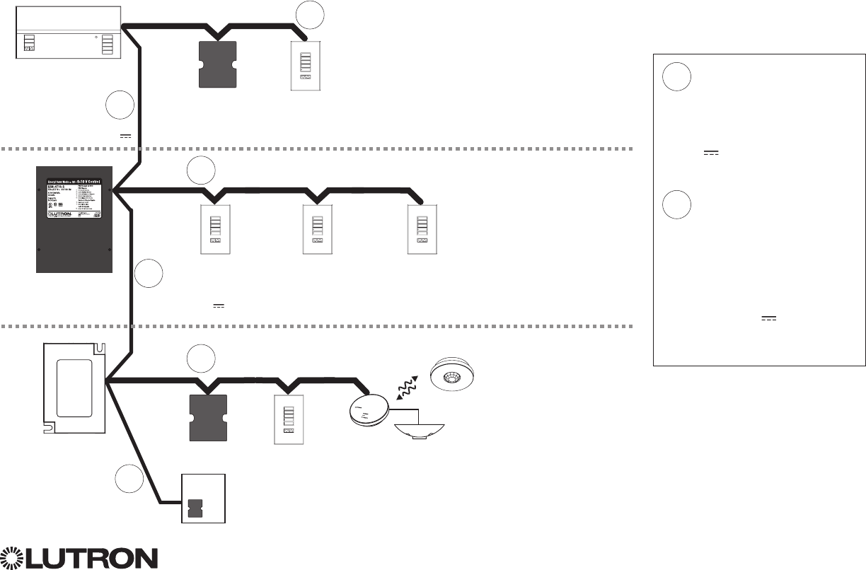
Wiring the GRAFIK Eye® QS Control Unit: Power Group Wiring Example
®
On the QS link, there are devices that supply power and devices that consume power. Each device has a specic number of Power
Draw Units (PDUs) it either supplies or consumes. A Power Group consists of one device that supplies power and one or more
devices that consume power; each Power Group may have only one power-supplying device. Refer to the QS Link Power Draw Units
specificationsubmittal(LutronPN369405)formoreinformationconcerningPDUs.
Within Power Groups on the QS link, connect all 4 terminals (1, 2, 3, and 4), shown by the letter A in the diagram. Between devices on
theQSlinkthatsupplypower,connectonlyterminals1,3,and4(NOTterminal2),shownbytheletterBonthediagram.
Wiring can be T-tapped or daisy-chained.
For additional information, see the complete installation and operation guide at www.lutron.com/qs
GRAFIK Eye® QS Control Unit Quick Installation and Operation Guide 8
LUTRON
LUTRON LUTRON
LUTRON
LUTRON
LUTRON
Power Group 1
Power Group 2
Power Group 3
A
A
B
B
(Do not connect
terminal 2: 24 V )
(Do not connect
terminal 2: 24 V )
GRAFIK Eye® QS
control unit
Supplies PDUs
QS Power Supply
Supplies PDUs
Energi Savr NodeTM
unit Supplies PDUs
Control Interfaces
Consume PDUs
Control Interfaces
Consume PDUs
Wallstations
Consume PDUs
Wallstations
Consume PDUs
Wallstations
Consume PDUs
QS Sensor Module with
Occupancy Sensor
Consumes PDUs
Connect all 4 terminals within
a power group:
1: Common
2: 24 V
3 and 4: Data
Connect only 3 terminals
between power groups:
1: Common
3 and 4: Data
Do not connect
Terminal 2: 24 V
A
B
Quantum® panel
Supplies PDUs
B
A
®
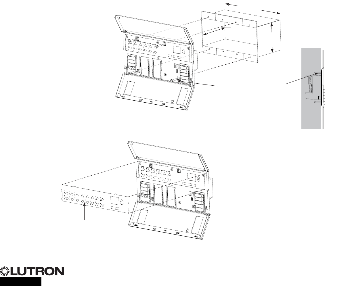
Completing Installation of the GRAFIK Eye® QS Control Unit
1. Mount the control unit in the wallbox as
shown using the four screws pro vid ed.
Note: Follow all local and national
electrical codes when installing IEC
PELV/NEC® Class 2 wiring with line
voltage/mains wiring.
2. Verify installation:
•Restore power.
•Press the top scene button. The LED will
light.
•Press the zone raise and lower buttons.
Make sure the control unit is dimming all
connected loads.
3. Apply the protective overlay to the control
unit.
Note: When tightening mounting
screws, make sure that the hinged
cover and faceplate will open fully,
as shown.
Wall
7.9 in
(200 mm)
3.5 in
(87 mm) 3.75 in
(95 mm)
Protective overlay
(apply after installation)
For additional information, see the complete installation and operation guide at www.lutron.com/qs
GRAFIK Eye® QS Control Unit Quick Installation and Operation Guide 9
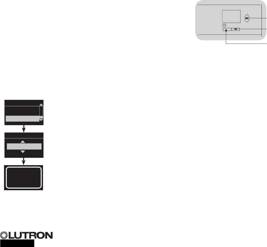
Entering and Exiting Programming Mode
Entering programming mode:
Press and hold the top and bottom scene
buttons simultaneously for 3 seconds. The
LEDs in the scene buttons will scroll from
top to bottom, confirming that you are in
programming mode, and the info screen will
display the main menu.
Exiting programming mode:
Press and hold the top and bottom scene
buttons simultaneously for 3 seconds. The
info screen will go to Scene 1.
Navigating Menus in Programming Mode
Master Buttons
The Master buttons allow you to move through the menu
choices. The current choice is highlighted on the info screen.
OK Button
The OK button chooses the current highlighted menu choice.
This will either take you to the next menu or accept a setting you
haveselected.WhenthescreendisplaysaYes/Noquestion,the
OK button is “Yes”.
Timeclock Button
The timeclock button functions as a “back” button during
programming mode. Pressing the timeclock button takes you
back one step in the current menu. Pressing it repeatedly
will eventually return you to the main menu, but will not exit
programmingmode.WhenthescreendisplaysaYes/No
question,theTimeclockbuttonis“No”.
®
Programming Mode
OK
123456
Press and hold the top and
bottom buttons for 3 seconds
to enter or exit programming
mode
Master buttons
OK button
Timeclock (back) button
Main menu
Scene setup
Timeclock
Scene 1
Fade time
3 seconds
For additional information, see the complete installation and operation guide at www.lutron.com/qs
GRAFIK Eye® QS Control Unit Quick Installation and Operation Guide 10
®
For additional information, see the complete installation and operation guide at www.lutron.com/qs
GRAFIK Eye® QS Control Unit Quick Installation and Operation Guide 11
Wireless Mode
Many models of the GRAFIK Eye® QS control unit support wireless communication
with other Lutron products. This feature allows for easy integration of wireless sensors,
keypads, remotes, and shades for single-room wireless applications, as well as
compatibility with other Lutron wireless systems such as RadioRA® 2.
(See the RadioRA®SetupGuide;LutronPN044254.)
Units supporting wireless communication are labeled “GRAFIK Eye® QS Wireless” on
the front label of the unit.
The wireless feature of the GRAFIK Eye® QS Wireless control unit has three (3) modes
of operation.
•Disabled: Use for wired-only systems.
•Enabled: The GRAFIK Eye® QS Wireless control unit will respond to any programming
commands from nearby Lutron QS wireless (and compatible) products.
•Ignore Programming (default): The GRAFIK Eye® QS Wireless control unit will only
respond to normal operation commands from wireless devices associated while in
Enabled mode.
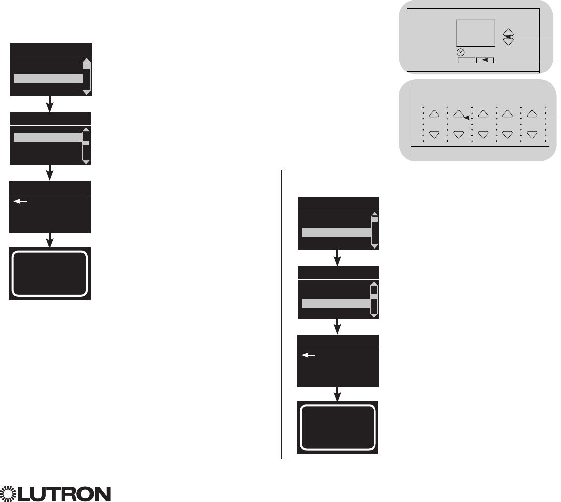
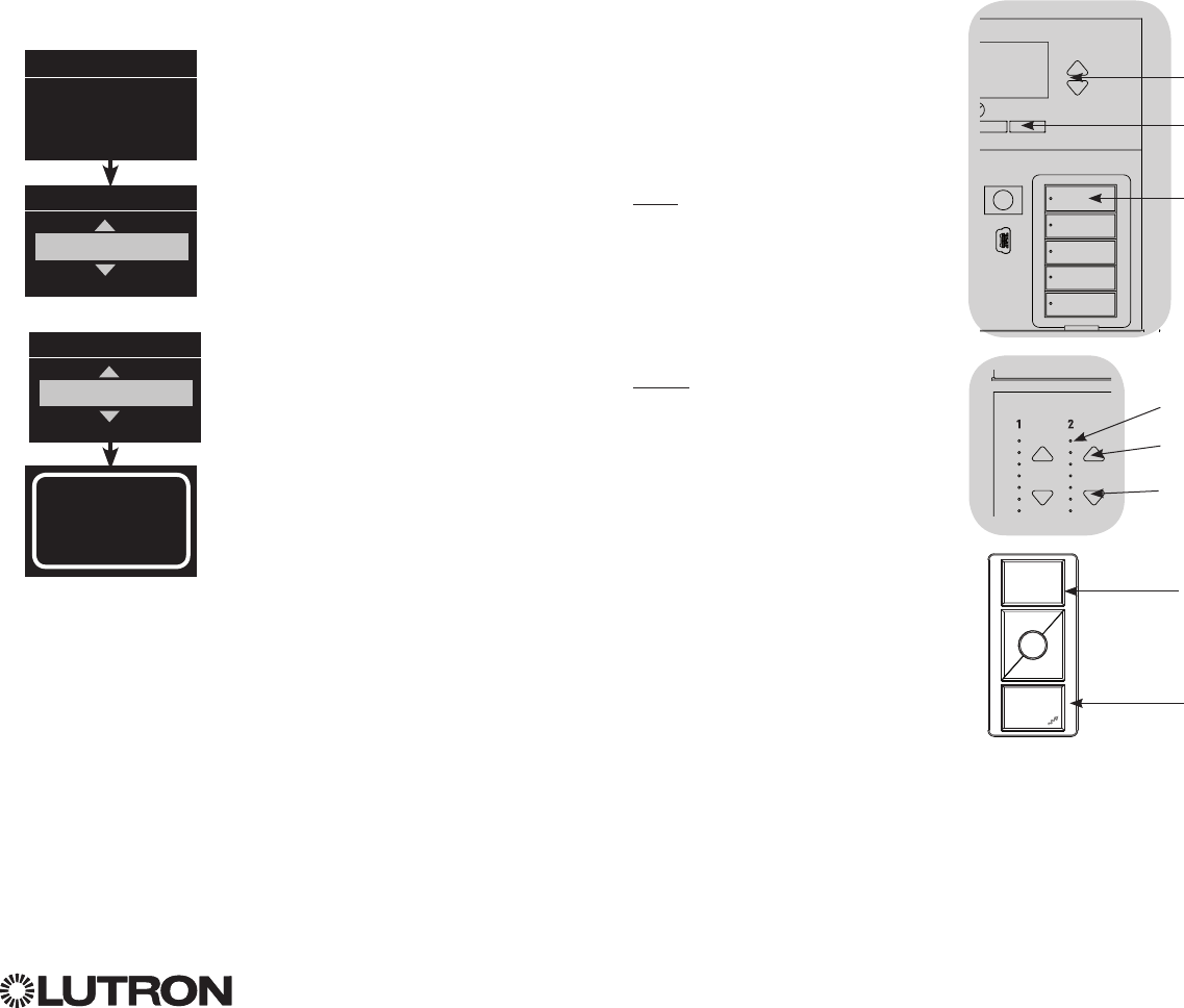
Changing the wireless mode of the GRAFIK Eye® QS Wireless control unit:
1. Enter programming mode.
2. Use the Master buttons to highlight “Wireless Mode” and press
the OK button to accept.
3. Use the Master buttons to highlight the desired wireless mode,
and press the OK button to accept.
4. The info screen will display a confirming “Saved” message.
5. Exit programming mode.
Notes
• The wireless signal has a range of 30 ft (9 m) through standard
construction or 60 ft (18 m) line of sight.
• WhenusedwithinaRadioRA® 2 system, the wired QS link on the
GRAFIK Eye® QS control unit is disabled, and certain features
that do not pertain to RadioRA® 2 are not accessible.
Wireless Mode
Enabled
Saved
Saved
Main menu
Shade labels
Wireless Mode
FCC Information
Changes or modifications not expressly approved
by Lutron Electronics Co. could void the user’s
authority to operate this equipment.
Note: This equipment has been tested and
found to comply with the limits for a Class B
digital device, pursuant to Part 15 of the FCC
rules and Industry Canada license-exempt RSS
standard(s) . Operation is subject to the
following: (1) This device may not cause harmful
interference, and (2) this device must accept
any interference received, including interference
that may cause undesired operation.
These limits are designed to provide
reasonable protection against harmful interference
in a residential and commercial installation. This
equipment generates, uses, and can radiate
radio frequency energy and, if not installed and
used in accordance with the instructions, may
cause harmful interference to radio or television
reception. However, there is no guarantee
that interference will not occur in a particular
installation. If this equipment does cause harmful
interference to radio or television reception, which
can be determined by turning the equipment off
and on, the user is encouraged to try to correct
the interference by one or more of the following
measures:
•
Reorientorrelocatethereceivingantenna.
•
Increasetheseparationbetweentheequipment
and receiver.
•
Connecttheequipmentintoanoutletona
circuit different from that to which the receiver is
connected.
•
Consultthedealeroranexperiencedradio/TV
technician for help.
OK
Master
buttons
OK
button
Timeclock
(back) button
®
For additional information, see the complete installation and operation guide at www.lutron.com/qs
GRAFIK Eye® QS Control Unit Quick Installation and Operation Guide 12
Assigning Load Types
1. Enter programming mode.
2. Use the Master buttons to highlight
“Zone setup” and press the
OK button to accept.
3. Use the Master buttons to highlight
“Load type”. Press the OK button to
accept. See “Setting Load Types”
table on the next page.
4. Use the zone raise/lower buttons to
choose the load type for that zone.
See the list on the next page for
supported load types. Press the OK
button to accept.
5. The info screen will confirm that
your load type has been saved.
6. Exit programming mode.
Zone Setup
OK
123456
Master
buttons
OK button
Main menu
CCI Setup
Zone setup
OK
123456Use the
zone
raise/lower
buttons to
choose the
load type for
that zone.
Zone Setup
Non-Dim Load Type
Load Type
Set zones
Saved
Load Type
Assigning Non-Dim Load Type
Zones assigned to non-dim loads have three available configurations:
•LOFO: Last On, First Off
•FOFO: First On, First Off
•FOLO: First On, Last Off
Scenes made up of both dim and non-dim
load types will toggle the non-dim loads
before the dim loads in a “First” on/off
configuration, and after the dim loads in a
“Last” on/off configuration.
1. Enter programming mode.
2. Use the Master buttons to highlight “Zone
setup” and press the OK button to accept.
3.UsetheMasterbuttonstohighlight“Non-Dim
Load type”. Press the OK button to accept.
See “Setting Load Types” table on the next
page.
4. Use the zone raise/lower buttons to choose
the non-dim load type for that zone. (Zones
not programmed as non-dim will be displayed
as Unaffected.) Press the OK button to
accept.
5. The info screen will confirm that your load
type has been saved.
6. Exit programming mode.
Main menu
CCI Setup
Zone setup
Zone Setup
Load Type
Load Type
Set zones
Saved
Non-Dim Load Type
®
For additional information, see the complete installation and operation guide at www.lutron.com/qs
GRAFIK Eye® QS Control Unit Quick Installation and Operation Guide 13
Zone Setup (continued)
Load Type Notes
• Allelectroniclow-voltage
(ELV) lighting used with an
interface must be rated for reverse
phase control dimming. Before
installing an ELV light source,
verify with the manufacturer that
their transformer can be dimmed.
When dimming, an ELV interface
(such as the PHPM-PA-DV-WH)
must be used with the control
unit.
• ForallDMXorRGB/CMYDMX
lighting,anexternalDMXinterface
(suchastheQSE-CI-DMX)must
be used with the control unit.
• Maximumtotallightingloadfor
Lutron® Tu-Wire® and Advance
MarkX® electronic dimming
ballasts (120 to 127 V only)
must not exceed 6 A per zone or
16 A per unit.
Zone ratings:
• Notallzonesmustbeconnected;
however, connected zones must
have a minimum load:
120 - 127 V : 25 W
220 - 240 V : 40 W
• Maximumzoneloads:
120 - 127 V : 800 W
220 - 240 V : 1200 W
• Maximumtotallightingloadfor
magnetic low-voltage (MLV) varies
by input voltage:
120 - 127 V : 800 VA / 600 W
220 - 240 V : 1200 VA / 960 W
LUTRON
LUTRON
LUTRON
LUTRON
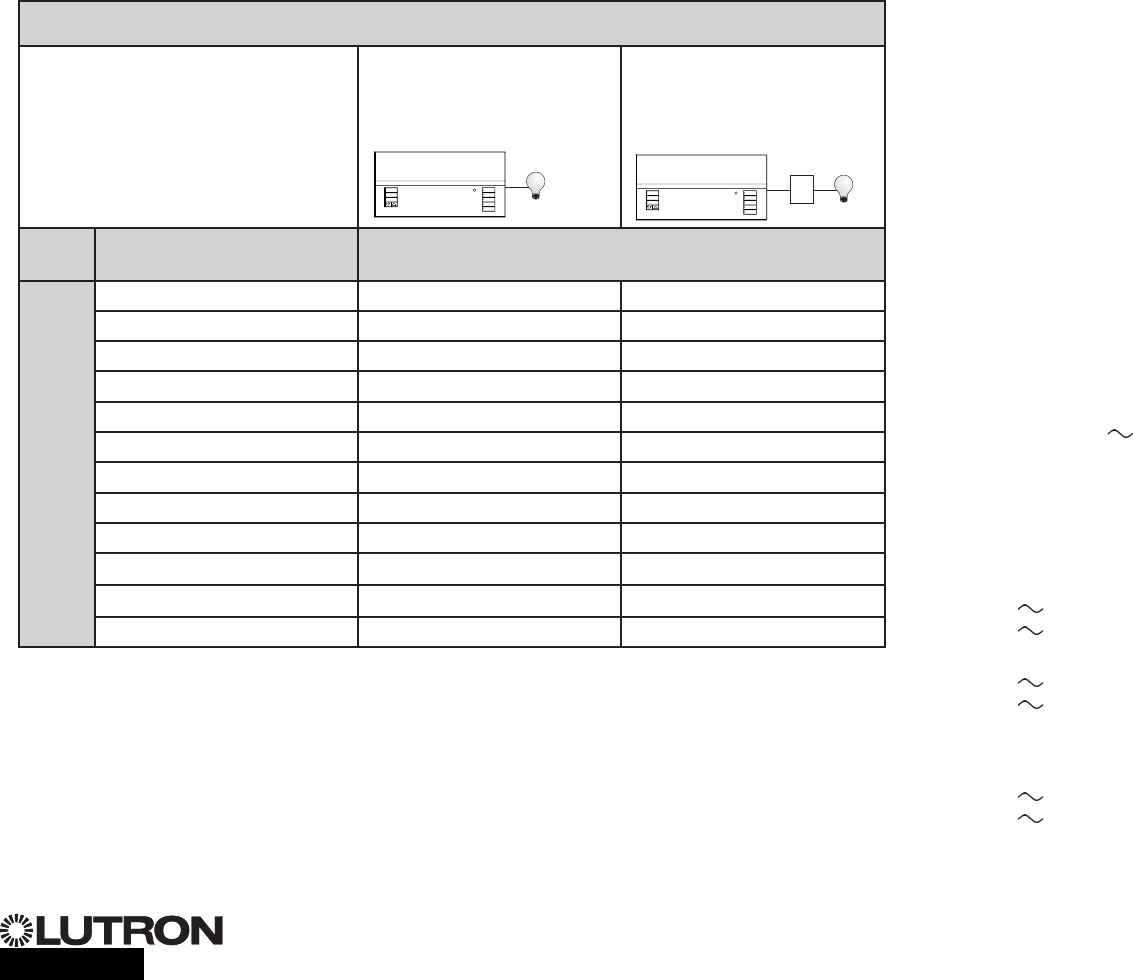
Setting Load Types
Direct control via
GRAFIK Eye® QS
control unit
Control via
power module or
interface
Fixture load type Choose this load type from the menu
on the GRAFIK Eye® QS control unit:
Zones
1 – 6
Incandescent Incandescent Power module
MLV (magnetic low-voltage) MLV Power module
ELV (electronic low-voltage) — Power module
Hi-Lume®/Eco-10®— Fluorescent module
0-10 V — Fluorescent module
Non-dim lighting loads Non-dim Non-dim
Neon/Cold cathode Neon, CC Neon, CC
Tu-Wire®Tu-Wire Tu-Wire
Advance Mark X®Tu-Wire Tu-Wire
DMX — DMX
RGB/CMY DMX — RGB/CMY DMX
Cree LR4/LR6 LED Cree LR4/LR6 LED Fluorescent module
Power
module or
interface
®
For additional information, see the complete installation and operation guide at www.lutron.com/qs
GRAFIK Eye® QS Control Unit Quick Installation and Operation Guide 14
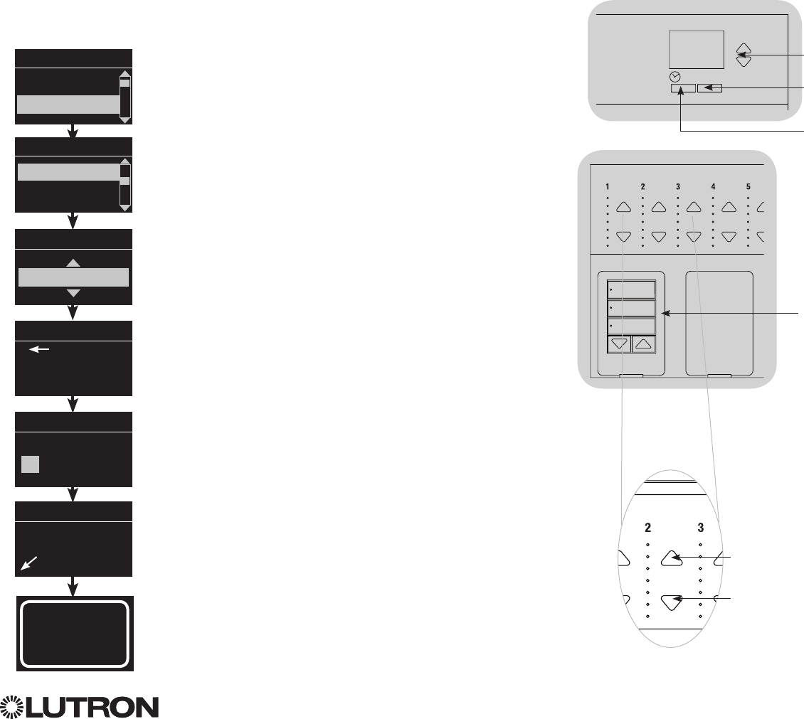
Scene Setup
Setting Zone Levels, Fade Rates, and Shade Group Actions
1. Enter programming mode.
2. Use the Master buttons to highlight “Scene setup” and press
the OK button to accept.
3. Use the Master buttons to highlight “Levels” to adjust lighting
and/or shade levels. Press the OK button to accept. Use the
Master buttons to highlight the scene number of your desired
scene. Press the OK button to accept.
4. Set each zone to the desired light level for this scene using
the zone raise/lower buttons. The info screen will display the
zone and percentage as you adjust it.
To set a zone as unaffected, lower the light levels all the way
to off, then hold the zone lower button for 3 seconds. The
screen will display “---” and the three middle LEDs for the
zone will be lit to indicate this zone is unaffected by the scene
(the zone will not change when this scene is initiated).
When all zones are at the desired level, press the OK button to
accept.
5. Use the Master buttons to set the fade time for this scene.
Press the OK button to accept.
6. Note: This step is applicable only if you have shades on your
system. If you do not have or do not wish to set shade groups
for this scene, press the OK button to skip this step.
Set each shade group to the desired level for this scene.
When all shade groups are at the desired level, press the OK
button to accept.
For shade programming, see the full installation and operation
guide at www.lutron.com/qs.
7. The info screen will confirm that your scene has been saved.
8. Exit programming mode.
Main menu
Timeclock
Scene setup
Scene setup
Labels
Levels
Scene 1
Adjust fade
seconds
Scene 1
Set shade
Groups
3 seconds
Scene 1
Set zones
Scene setup
Scene 1
Saved
3
Shade
button group
OK
OK
Zone raise
Zone lower
OK
Master
buttons
OK
button
Timeclock
(back) button
®
For additional information, see the complete installation and operation guide at www.lutron.com/qs
GRAFIK Eye® QS Control Unit Quick Installation and Operation Guide 15
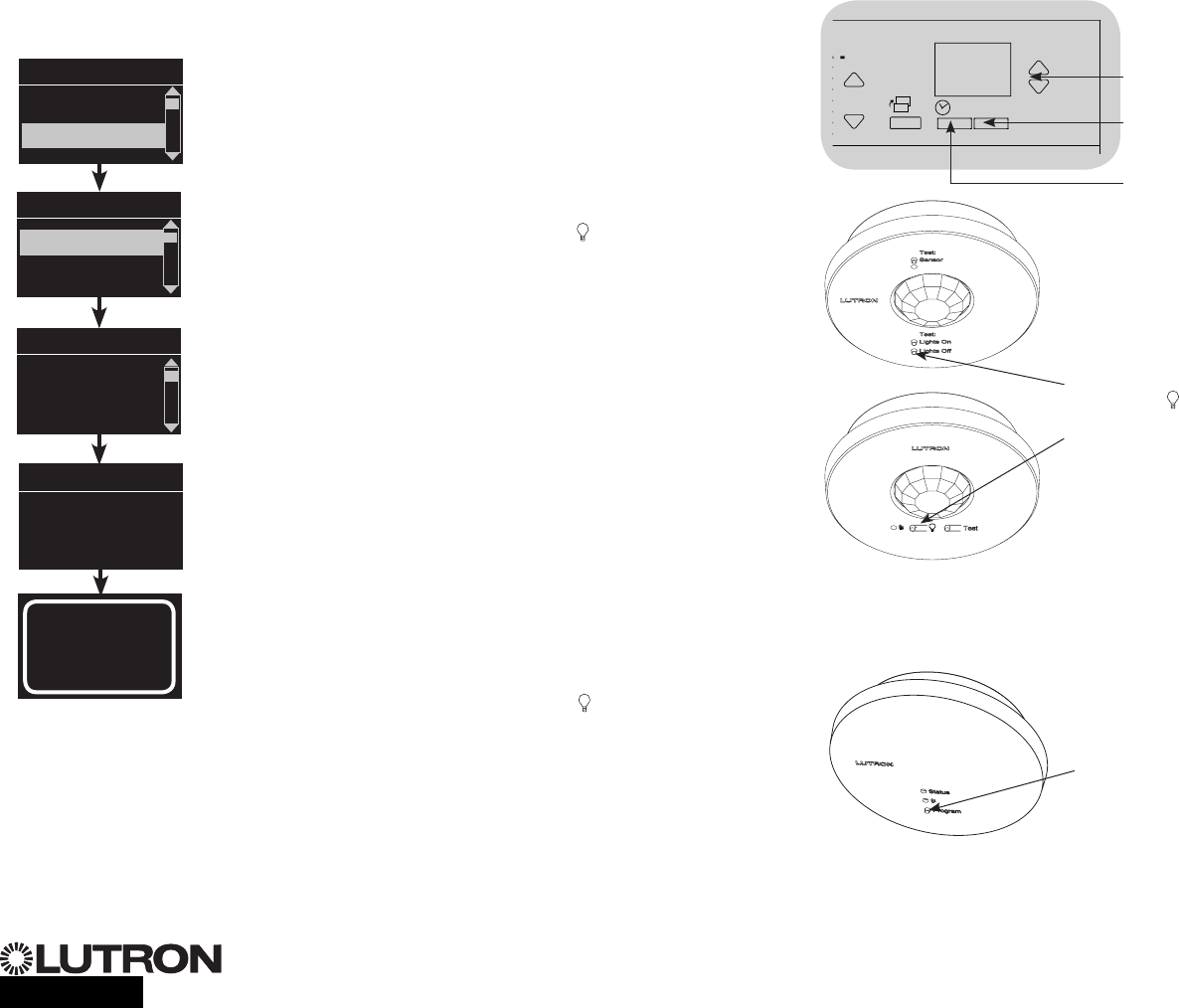
Associating wireless occupancy sensors and GRAFIK Eye® QS Wireless control units
(for wireless enabled units only):
1. Make sure the wireless mode of the GRAFIK Eye® QS control
unit is “Enabled”.
2. Enter programming mode.
3. Use the Master buttons to highlight “Sensor setup” and press
the OK button to accept.
4. Use the Master buttons to highlight “Add wireless sensors” and
press the OK button to accept.
5. Press and hold the “Lights Off” button ( on some sensors) on
the occupancy sensor for 6 seconds. The lens will start flashing
and the info screen on the GRAFIK Eye® QS Wireless control unit
willdisplaythesensor’sserialnumber.
6. Press the OK button on the GRAFIK Eye® QS control unit. A
screen will confirm that the sensor has been assigned.
(To disassociate a wireless occupancy sensor from the GRAFIK
Eye® QS control unit, Refer to the Radio Powr SavrTM occupancy
sensor install guide to return the sensor to its “out-of-box”
functionality. Doing so will remove its programming from the
GRAFIK Eye® QS control unit.)
7. Repeat the above steps for all desired sensors.
8. Exit programming mode.
Associating wireless occupancy sensors through
QS Sensor Modules (QSM):
1. Press and hold the Program button on the QSM for 3 seconds
to enter programming mode. There will be 1 audible beep
and the Status LED will begin flashing. The info screen on the
GRAFIK Eye® QS control unit will display that the QSM is in
programming mode.
2. Press and hold the “Lights Off” button ( on some sensors) on
the occupancy sensor for 6 seconds. There will be 3 audible
beeps from the QSM to verify association.
3. Press and hold the Program button on the QSM for 3 seconds
to exit programming mode.
Note: The wireless signal has a range of 30 ft (9 m) through
standard construction or 60 ft (18 m) line of sight.
Occupancy Sensor Setup
OK
1 2 34569 10 11 12 13 14 7815
16
9-16
1-8
Master
buttons
OK
button
Timeclock
(back) button
Main menu
Zone Setup
Sensor Setup
Occupancy
xxxx-xxxx
Press OK to Save
Add wireless sensors
Initiate association
of sensors
Saved
*Assigned*
Sensor Setup
Daylight
Add wireless sensors
Program button
Press and hold
“Lights Off” or
button to associate/
disassociate
QS Sensor Module (QSM)
Radio Powr SavrTM
Occupancy Sensors
®
For additional information, see the complete installation and operation guide at www.lutron.com/qs
GRAFIK Eye® QS Control Unit Quick Installation and Operation Guide 16
Occupancy Sensor Setup
Scene Mode
This step allows you to assign up to four occupancy sensors to the GRAFIK Eye® QS
control unit.
Selecting Sensors
1. If not already done, associate occupancy sensors and set to
“Scene Mode”.
2. Use the Master buttons to highlight “Setup” and press the
OK button to accept. The info screen will display “Searching”
while the unit detects available occupancy sensors.
3. Use the Master buttons to scroll through the list of available
occupancy sensors. When the desired sensor is displayed,
press the OK button to select it. Then choose “Assign” or
“Unassign” from the following menu and press OK. Once a
sensor has been assigned, it will appear with an asterisk (*) in
the sensor list. Repeat for additional sensors.
Note: If wireless sensors are not found, verify that they are
associated correctly.
Setting the Sensor Action
1. Press the Timeclock (back) button to return to the Occ Sensor
screen. Use the Master buttons to highlight “Actions” and
press the OK button. By default, the occupied scene is set to
“NoAction”andtheunoccupiedsceneissetto“SceneOff”.
2. Use the Master buttons to highlight the scene you wish to
use for occupied status and press the OK button to accept.
Repeat for the scene you wish to use for unoccupied status.
Press the OK button to accept.
3. Exit programming mode.
Saved
Saved
3 seconds
Occ Sensor
Setup
Actions
Occupied Scene
Scene 1
Unoccupied Scene
Scene Off
Occ Sensor
Labels
Setup
Sensor x/y
xxxx-xxxx
RF
Sensor *x/y
xxxx-xxxx
RF
Assignment
Unassign
Assign
Saved
*Assigned*
Saved
Searching
OK
Master
buttons
OK
button
Timeclock
(back) button
®
For additional information, see the complete installation and operation guide at www.lutron.com/qs
GRAFIK Eye® QS Control Unit Quick Installation and Operation Guide 17
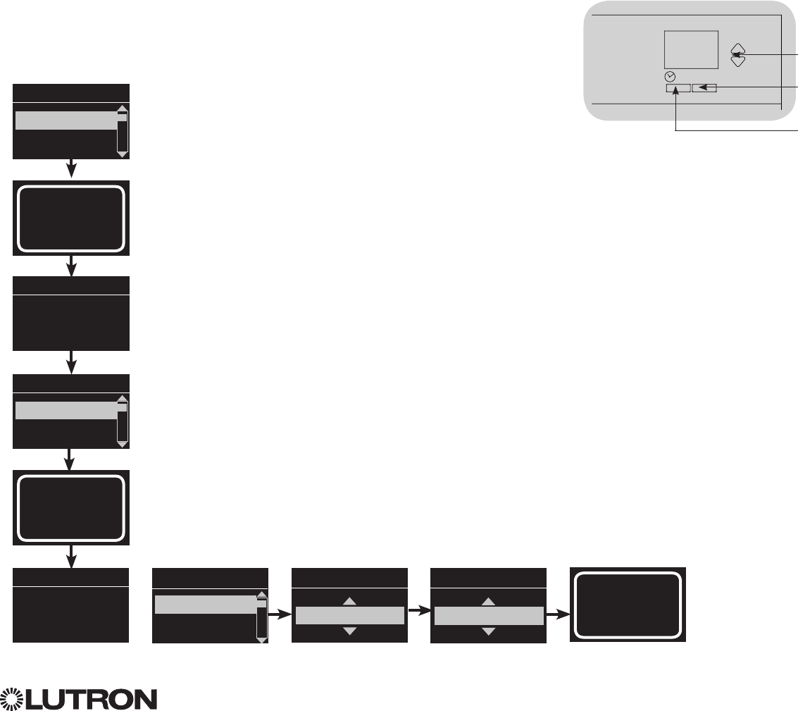
Occupancy Sensor Setup
Configuring Occupancy Sensor Settings (optional)
Occupancy Sensor Settings
Note: These settings affect all sensors assigned to the
GRAFIK Eye® QS control unit.
Grace Period: If the GRAFIK Eye® QS control unit is
transitioning to an unoccupied state, motion detected within
the grace period will return the lights to the previously
occupied level.
Range: 15 – 30 seconds (default 15 seconds).
Vacancy Delay: An additional time delay after vacancy is
detected and before unoccupied action occurs. Use when
occupancy sensor does not provide sufficient delay.
Range: 0 – 30 minutes (default 0 minutes).
Auto Turnoff: If lights assigned to an occupancy sensor are
turned on manually without the sensor reporting occupancy,
the GRAFIK Eye® QS control unit can be set to automatically
turn off the lights after a set time delay. Disable this feature by
setting the time delay to 0 (disabled).
Range: Disabled or 1 – 30 minutes (default Disabled).
Zone Fade: When in Zone Mode, lights can be set to fade to
the unoccupied levels over this period of time.
Range: 0 – 59 seconds; 1 – 10 minutes (default 10 seconds).
Configuring the Sensor Settings:
1. Enter programming mode.
2. Use the Master buttons to highlight “Sensor Setup” and press
the OK button to accept.
3. Use the Master buttons to highlight “Occupancy” and press
the OK button to accept.
4. Use the Master buttons to highlight “Settings” and press the
OK button to accept.
5. Use the Master buttons to highlight the setting you wish to
configure. Press the OK button to accept.
6. Use the Master buttons to adjust the value of the selected
setting. Press the OK button to accept.
7. The info screen will confirm that your setting has been saved.
8. Exit programming mode.
Auto Turnoff
5 minutes
Saved
Saved
Main menu
Zone Setup
Sensor Setup
Occ Sensor
Diagnostics
Settings
Settings
Zone Fade
Auto Turnoff
OK
Master
buttons
OK
button
Timeclock
(back) button
Sensor Setup
Daylight
Occupancy
®
For additional information, see the complete installation and operation guide at www.lutron.com/qs
GRAFIK Eye® QS Control Unit Quick Installation and Operation Guide 18
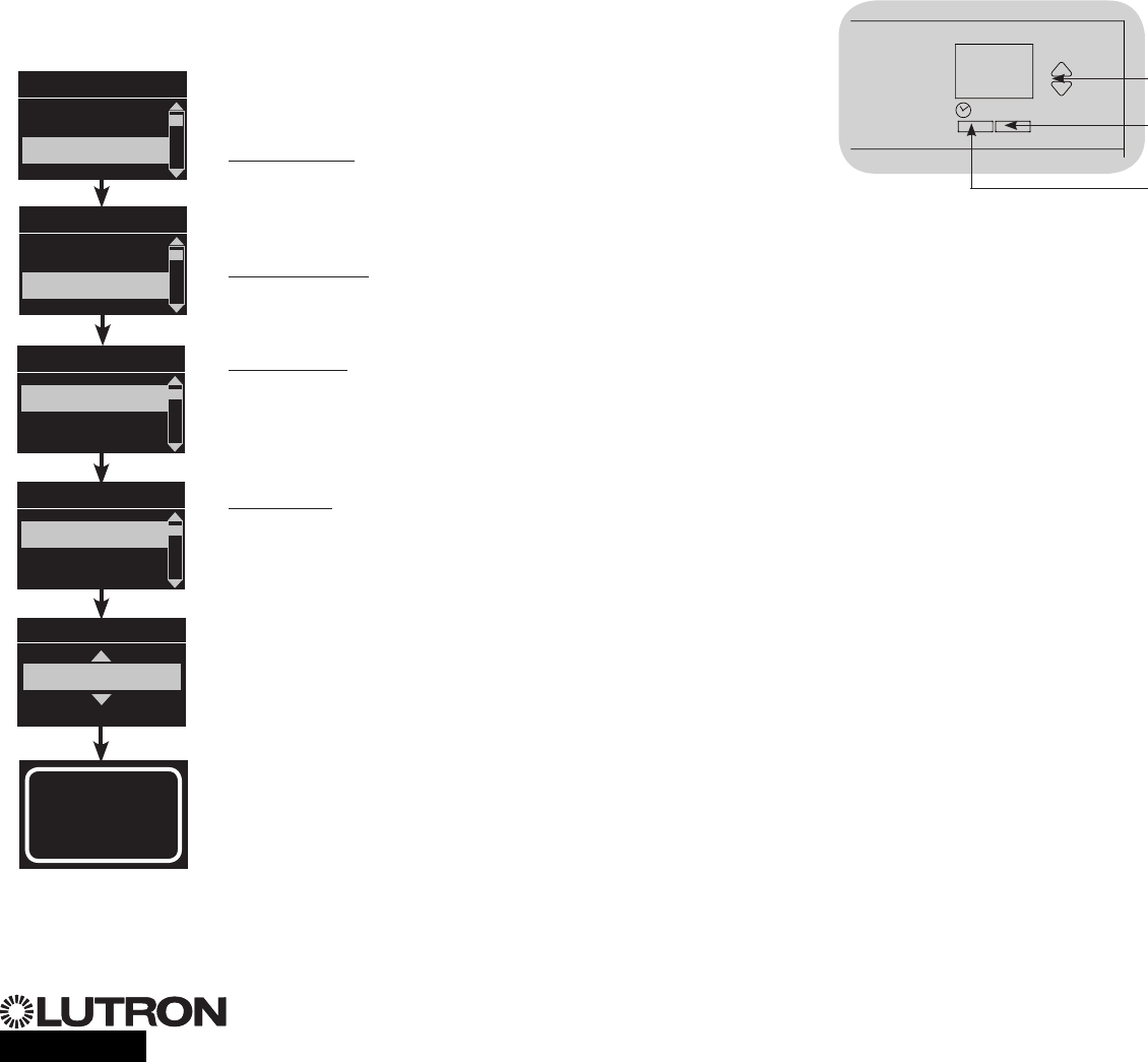
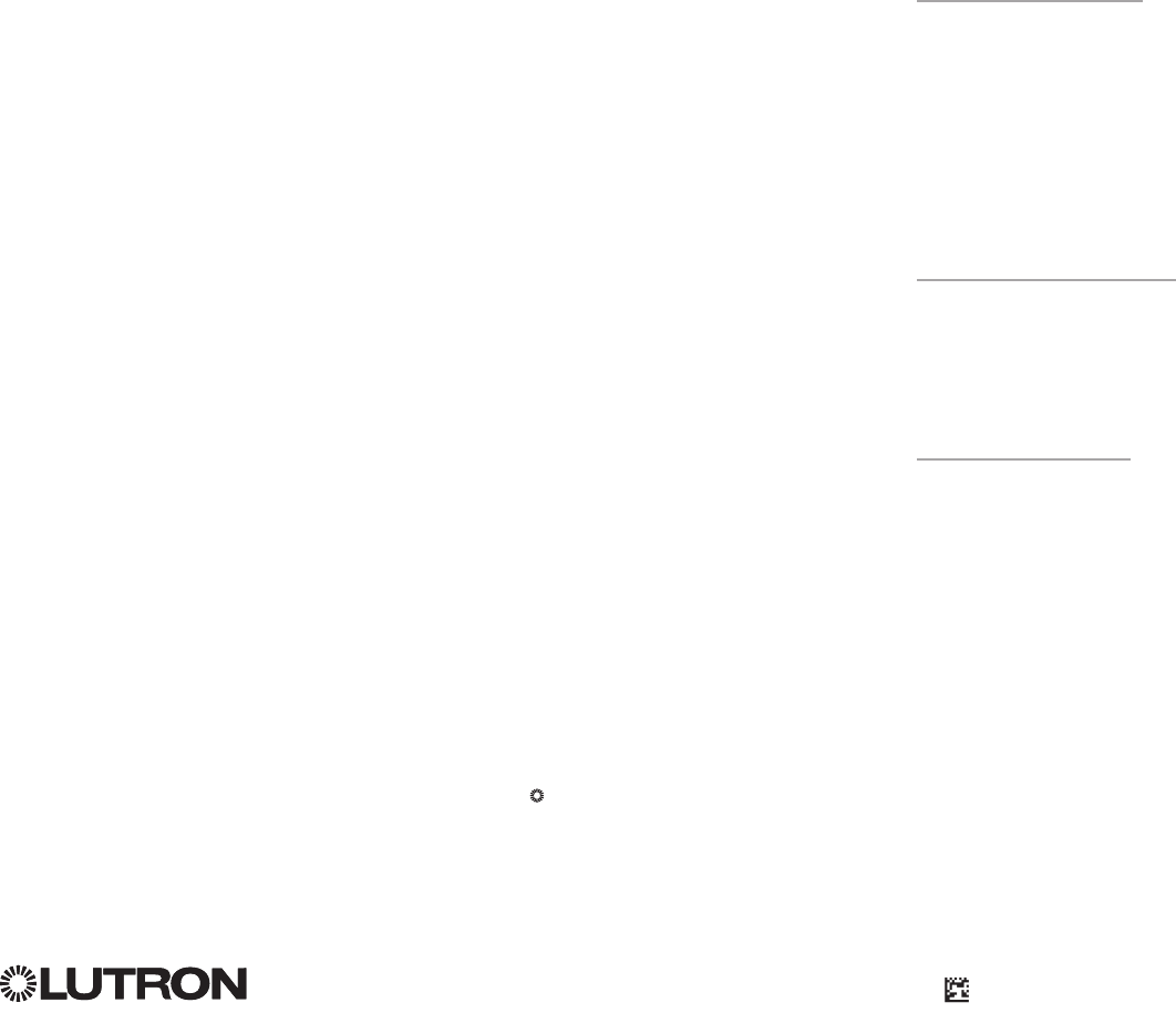
Associating the Pico® wireless control with a GRAFIK Eye® QS Wireless control unit:
(for wireless enabled GRAFIK Eye® QS control units only)
1. Make sure the wireless mode of the GRAFIK Eye® QS control unit is
“Enabled”.
2. On the Pico® wireless control, press and hold the top (on) and bottom (off)
buttons for 3 seconds. The info screen on the GRAFIK Eye® QS control unit
will display the Pico® options. Press the OK button on the GRAFIK Eye® QS
control unit to select the desired operation type for the Pico®.
3a. To assign the Pico® wireless control as a zone controller, use the Master
buttons to select “Zone” and press the OK button to accept. Use the zone
raise/lower buttons for a zone to select a desired preset level, and then
press the zone raise and lower buttons simultaneously for 1 second (until the
zone LEDs flash at the programmed preset level). Repeat for all zones you
wish to control with the Pico® wireless control.
OR
3b. To assign the Pico® wireless control as a scene controller, use the Master
buttons to select “Scene” and press the OK button to accept. Press and
hold the top scene button on the GRAFIK Eye® QS control unit for 3 seconds
(until the scene LEDs flash).
4. On the Pico® wireless control, press and hold the top and bottom buttons for
3 seconds until the LEDs on the GRAFIK Eye® QS control unit stop flashing.
Note:Thewirelesssignalhasarangeof30ft(9m)throughstandard
construction or 60 ft (18 m) line of sight.
Change type?
Zone
Change type?
Scene
Saved
Saved
Pico
Change type?
Press OK
Pico® Wireless Control Setup
OK
Zone LEDs
Zone Raise
Zone Lower
OR
OK
1 2 34569 10 11 12 13 14 7815 16
9-16
1-8
Press and
hold the
top scene
button for
3 seconds
to assign
Pico® as
a scene
controller.
Master
buttons
OK
button
Top/On
button
Bottom/Off
button
Pico®
Wireless
Control

®
For additional information, see the complete installation and operation guide at www.lutron.com/qs
GRAFIK Eye® QS Control Unit Quick Installation and Operation Guide 19
Troubleshooting
Symptom Possible Causes Solution
Unit does not power up
Unit does not control loads
Circuit breaker is tripping
Circuit Breaker is off Switch circuit breaker on
Miswire Verify wiring to unit and loads
System short circuited Find and correct shorts
System overload Verify zone/unit loading is within ratings (see Zone Setup section)
Zone control does not work
Zone control yields incorrect
results
Miswire Make sure loads are connected to the right zones
Loose or disconnected wire Connect zone wires to loads
Burned out lamps Replace bad lamps
Incorrect load type selected Assign the zone to the appropriate load type (see Zone Setup section)
Dimming limits set incorrectly Adjust High End/Low End values (see Zone Setup section)
One or more zones are
always “full on” and zone
intensity is not adjustable
Zone control affects more
than one zone
Miswire Make sure loads are connected to the right zones
Shorted line output Check wiring; if wiring is correct, call Lutron Technical Support
Faceplate is warm Normal operation Solid-state controls dissipate about 2% of the connected load as heat. No action is required
Unit does not allow scene
change or zone adjustments Unit is in wrong save mode Change to correct save mode
QS device in system has locked the unit Check programming and state of QS devices
Cannot program fade time
from “Scene Off” Fade time from “Scene Off” is not
programmable; can only program fade time to
“Scene Off”
Fade time from “Scene Off” is always 3 seconds
Integral (direct-wired) contact
closure input does not work Miswire Check wiring on contact closure input
Input CCI signal is not received Verify the input device is operating properly
Unit is in wrong CCI mode and/or type Change to correct CCI mode and/or type for your application
QS devices on link are not
working Miswire or loose connection on QS link Verify QS link wiring to all devices
QS device is not associated Place the QS device into programming mode, and hold the “Scene 1” button on the
GRAFIK Eye® QS control unit to associate the two devices
QS device programming is incorrect Verify the functionality and programming on the QS devices
Timeclock events do not
occur
Sunrise or sunset events do
not occur at the correct time
Timeclock is disabled Enable the timeclock
Time/date is not set correctly Set the time/date
Location is not set correctly Set the latitude and longitude of the unit’s location
Holiday schedule is in effect Normal schedule will resume when the holiday ends
®
Lutron Electronics Co., Inc.
One Year Limited Warranty
For a period of one year from the date of purchase, and subject
to the exclusions and restrictions described below, Lutron warrants
each new unit to be free from manufacturing defects. Lutron will,
at its option, either repair the defective unit or issue a credit equal
to the purchase price of the defective unit to the Customer against
the purchase price of comparable replacement part purchased
from Lutron. Replacements for the unit provided by Lutron or, at its
sole discretion, an approved vendor may be new, used, repaired,
reconditioned, and/or made by a different manufacturer.
If the unit is commissioned by Lutron or a Lutron approved third
party as part of a Lutron commissioned lighting control system, the
term of this warranty will be extended, and any credits against the
cost of replacement parts will be prorated, in accordance with the
warranty issued with the commissioned system, except that the
term of the unit’s warranty term will be measured from the date of
its commissioning.
EXCLUSIONS AND RESTRICTIONS
This Warranty does not cover, and Lutron and its suppliers are not
responsible for:
1. Damage, malfunction or inoperability diagnosed by Lutron or
a Lutron approved third party as caused by normal wear and
tear, abuse, misuse, incorrect installation, neglect, accident,
interference or environmental factors, such as (a) use of
incorrect line voltages, fuses or circuit breakers; (b) failure to
install, maintain and operate the unit pursuant to the operating
instructions provided by Lutron and the applicable provisions
of the National Electrical Code and of the Safety Standards
of Underwriter’s Laboratories; (c) use of incompatible devices
or accessories; (d) improper or insufficient ventilation; (e)
unauthorized repairs or adjustments; (f) vandalism; or (g) an act
of God, such as fire, lightning, flooding, tornado, earthquake,
hurricane or other problems beyond Lutron’s control.
2. On-site labor costs to diagnose issues with, and to remove,
repair, replace, adjust, reinstall and/or reprogram the unit or any
of its components.
3. Equipment and parts external to the unit, including those sold
or supplied by Lutron (which may be covered by a separate
warranty).
4. The cost of repairing or replacing other property that is damaged
when the unit does not work properly, even if the damage was
caused by the unit.
EXCEPT AS EXPRESSLY PROVIDED IN THIS WARRANTY,
THERE ARE NO EXPRESS OR IMPLIED WARRANTIES OF ANY
TYPE, INCLUDING ANY IMPLIED WARRANTIES OF FITNESS FOR
A PARTICULAR PURPOSE OR MERCHANTABILITY. LUTRON
DOES NOT WARRANT THAT THE UNIT WILL OPERATE WITHOUT
INTERRUPTION OR BE ERROR FREE.
NO LUTRON AGENT, EMPLOYEE OR REPRESENTATIVE HAS
ANY AUTHORITY TO BIND LUTRON TO ANY AFFIRMATION,
REPRESENTATION OR WARRANTY CONCERNING THE UNIT.
UNLESS AN AFFIRMATION, REPRESENTATION OR WARRANTY
MADE BY AN AGENT, EMPLOYEE OR REPRESENTATIVE IS
SPECIFICALLY INCLUDED HEREIN, OR IN STANDARD PRINTED
MATERIALS PROVIDED BY LUTRON, IT DOES NOT FORM A
PART OF THE BASIS OF ANY BARGAIN BETWEEN LUTRON AND
CUSTOMER AND WILL NOT IN ANY WAY BE ENFORCEABLE BY
CUSTOMER.
IN NO EVENT WILL LUTRON OR ANY OTHER PARTY BE LIABLE
FOR EXEMPLARY, CONSEQUENTIAL, INCIDENTAL OR SPECIAL
DAMAGES (INCLUDING, BUT NOT LIMITED TO, DAMAGES FOR
LOSS OF PROFITS, CONFIDENTIAL OR OTHER INFORMATION, OR
PRIVACY; BUSINESS INTERRUPTION; PERSONAL INJURY; FAILURE
TO MEET ANY DUTY, INCLUDING OF GOOD FAITH OR OF
REASONABLE CARE; NEGLIGENCE, OR ANY OTHER PECUNIARY
OR OTHER LOSS WHATSOEVER), NOR FOR ANY REPAIR WORK
UNDERTAKEN WITHOUT LUTRON’S WRITTEN CONSENT ARISING
OUT OF OR IN ANY WAY RELATED TO THE INSTALLATION,
DEINSTALLATION, USE OF OR INABILITY TO USE THE UNIT OR
OTHERWISE UNDER OR IN CONNECTION WITH ANY PROVISION
OF THIS WARRANTY, OR ANY AGREEMENT INCORPORATING
THIS WARRANTY, EVEN IN THE EVENT OF THE FAULT, TORT
(INCLUDING NEGLIGENCE), STRICT LIABILITY, BREACH OF
CONTRACT OR BREACH OF WARRANTY OF LUTRON OR ANY
SUPPLIER, AND EVEN IF LUTRON OR ANY OTHER PARTY WAS
ADVISED OF THE POSSIBILITY OF SUCH DAMAGES.
NOTWITHSTANDING ANY DAMAGES THAT CUSTOMER
MIGHT INCUR FOR ANY REASON WHATSOEVER (INCLUDING,
WITHOUT LIMITATION, ALL DIRECT DAMAGES AND ALL
DAMAGES LISTED ABOVE), THE ENTIRE LIABILITY OF LUTRON
AND OF ALL OTHER PARTIES UNDER THIS WARRANTY ON ANY
CLAIM FOR DAMAGES ARISING OUT OF OR IN CONNECTION
WITH THE MANUFACTURE, SALE, INSTALLATION, DELIVERY,
USE, REPAIR, OR REPLACEMENT OF THE UNIT, OR ANY
AGREEMENT INCORPORATING THIS WARRANTY, AND
CUSTOMER’S SOLE REMEDY FOR THE FOREGOING, WILL BE
LIMITED TO THE AMOUNT PAID TO LUTRON BY CUSTOMER
FOR THE UNIT. THE FOREGOING LIMITATIONS, EXCLUSIONS
AND DISCLAIMERS WILL APPLY TO THE MAXIMUM EXTENT
ALLOWED BY APPLICABLE LAW, EVEN IF ANY REMEDY FAILS
ITS ESSENTIAL PURPOSE.
TO MAKE A WARRANTY CLAIM
To make a warranty claim, promptly notify Lutron within the
warranty period described above by calling the Lutron Technical
Support Center at (800) 523-9466. Lutron, in its sole discretion, will
determine what action, if any, is required under this warranty. To
better enable Lutron to address a warranty claim, have the unit’s serial
and model numbers available when making the call. If Lutron, in its
sole discretion, determines that an on-site visit or other remedial action
is necessary, Lutron may send a Lutron Services Co. representative
or coordinate the dispatch of a representative from a Lutron approved
vendor to Customer’s site, and/or coordinate a warranty service call
between Customer and a Lutron approved vendor.
This warranty gives you specific legal rights, and you may also
have other rights which vary from state to state. Some states do
not allow limitations on how long an implied warranty lasts, so the
above limitation may not apply to you. Some states do not allow
the exclusion or limitation of incidental or consequential damages,
so the above limitation or exclusion may not apply to you.
NEC is a registered trademark of the National Fire Protection
Association, Quincy, Massachusetts.
Advance Mark X is a registered trademark of the Advance
Transformer Company.
Lutron,
®
, Sivoia, Hi-lume, Eco-10, Tu-Wire, Radio RA, Pico,
seeTouch, Quantum, and GRAFIK Eye are registered trademarks and
Radio Powr Savr and Energi Savr Node are trademarks of Lutron Electron-
ics Co., Inc.
© 2012 Lutron Electronics Co., Inc.
Internet: www.lutron.com
E-mail: product@lutron.com
WORLD HEADQUARTERS
USA
Lutron Electronics Co., Inc.
7200 Suter Road, Coopersburg, PA 18036-1299
TEL +1.610.282.3800
FAX+1.610.282.1243
Toll-Free1.888.LUTRON1
Technical Support 1.800.523.9466
North and South America Technical Hotlines
USA, Canada, Caribbean: 1.800.523.9466
Mexico: +1.888.235.2910
Central/South America: +1.610.282.6701
EUROPEAN HEADQUARTERS
United Kingdom
Lutron EA Ltd.
6 Sovereign Close, London, E1W 3JF United Kingdom
TEL +44.(0)20.7702.0657
FAX+44.(0)20.7480.6899
FREEPHONE(UK)0800.282.107
Technical support +44.(0)20.7680.4481
ASIAN HEADQUARTERS
Singapore
Lutron GL Ltd.
15 Hoe Chiang Road, #07-03, Tower 15,
Singapore 089316
TEL +65.6220.4666
FAX+65.6220.4333
Asia Technical Hotlines
NorthernChina:10.800.712.1536
Southern China: 10.800.120.1536
Hong Kong: 800.901.849
Indonesia: 001.803.011.3994
Japan: +81.3.5575.8411
Macau: 0800.401
Singapore: 800.120.4491
Taiwan: 00.801.137.737
Thailand: 001.800.120.665853
Other countries: +65.6220.4666
Warranty
Lutron Electronics Co., Inc.
P/N032-402Rev.A02/2012
Contact Information