Lutron Electronics 0107 In-wall dimmer User Manual
Lutron Electronics Company Inc In-wall dimmer
Contents
User manual
Installation Instructions
Please Read Before Installing
0301742 Rev A
GrafikTT
1. CAUTION: To avoid overheating and possible damage to other equipment, do
not use to control receptacles, fluorescent lighting fixtures, motor-operated
appliances, transformer-supplied appliances, or electronic low-voltage
lighting fixtures.
2. Install in accordance with all national and local electrical codes.
3. When no “grounding means” exist in wallbox, the NEC® allows dimmer without
a grounding connection to be installed as a replacement if 1) a nonmetallic,
noncombustible faceplate is used with nonmetallic attachment screws or 2) the
circuit is protected by a ground fault circuit interrupter (GFCI). For this type of
installation, cap or remove the green ground wire on the dimmer, and use an
appropriate wallplate, such as a Lutron® GrafikTTM series wallplate.
4. GrafikTTM dimmers are not compatible with standard 3-way switches. Use only with
companion dimmers (GT-AD-S or GT-AD).
5. Companion dimmers (GT-AD-S or GT-AD) cannot be used individually but must be
used in conjunction with a GrafikTTM dimmer in a multi-location application.
6. In any multi-location circuit, use only one GrafikTTM dimmer with up to four
companion dimmers.
7. GrafikTTM dimmer settings such as Light Bar Intensity and Speaker On/Off can be
modified using Advanced Programming Mode. For instructions and information on
how to use Advanced Programming Mode, please visit www.lutron.com/grafikT or
call Lutron® Technical Support at 1.800.523.9466.
Lutron Electronics Co., Inc.
7200 Suter Road
Coopersburg, PA 18036-1299
Installation
Important Notes
Compatible LEDs
Dimmers LED Incand. / Halogen Hi-lume® A-Series LTE LED Drivers
GTJ-150 150 W
600 W
—
GT-150 150 W
GT-250M 250 W
350 W
8 maximum
GTJ-250M 250W
RRT-25CL 250 W
HQRT-25CL 250 W
Companion dimmers
GT-AD-S For use with HQRT-25CL and RRT-25CL
GT-AD For use with all other models
120 V~ 60 Hz
Cree®: 499485; CR6X-PP2
Philips®: 426122(9290002330)(822580)(bc=046677426125)
EcoSmart®: ECO-575L
Sylvania®: 78390 (LED8R20/DIM/SE/830/RP)
FEIT (Utilitech): PAR38/LEDG5
For a complete list of compatible LEDs, please visit: www.lutron.com/LED
1.800.523.9466 U.S.A. | Canada | Caribbean
+1.888.235.2910 Mexico
+1.610.282.3800 Others
www.lutron.com
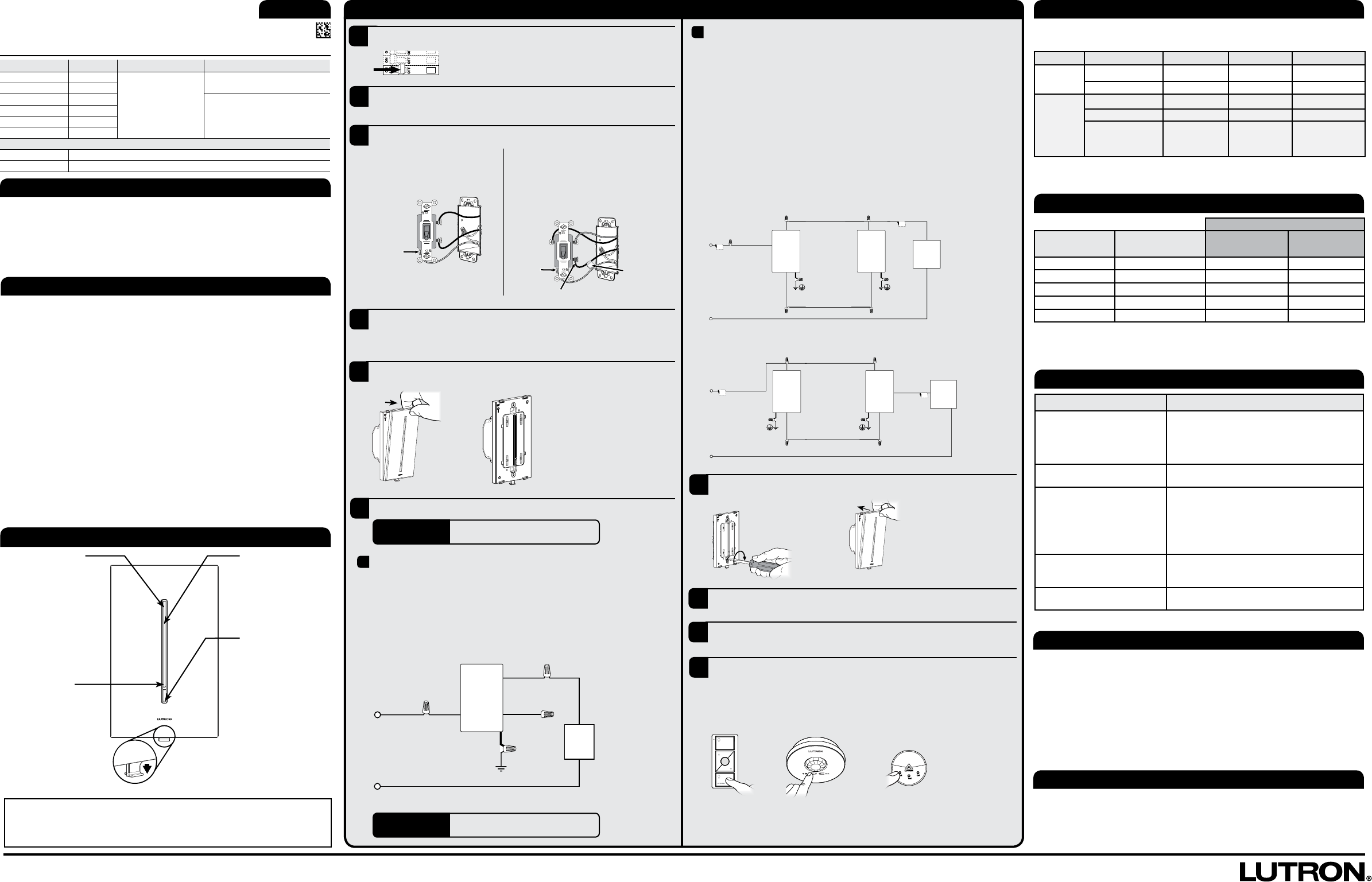
Multi-location - Lights can be dimmed from multiple locations.
One location will be replaced by a GrakTTM dimmer and the other location(s) by a GrakTTM
companion dimmer. The dimmer can be wired on the line-side or the load-side.
Dimmer
Connect the green ground wire on the dimmer to the green or bare ground wire in the wallbox
(See Important Note 3
at left
).
Connect tagged wire removed from the switch to the black wire on the dimmer.
Connect one of the remaining wires removed from switch to the red wire on the dimmer.
Connect the remaining wire removed from the switch to the blue wire on the dimmer.
Companion Dimmer
Connect the green wire on the dimmer to the green or bare ground wire in the wallbox (See
Important Note 3
at left).
Connect the same color wire connected to the red wire on the dimmer to the red wire on the
companion dimmer, along with the tagged wire.
Connect the remaining wire to the blue wire on the companion dimmer.
6a
Ganging and Derating
When combining controls in the same wallbox, derating is required. No derating is
required for companion dimmers.
1 Designed for use with permanently installed LED, incandescent, or tungsten halogen only.
Control 1Load Type Not Ganged End of Gang Middle of Gang
GT-150
GTJ-150
LED 150 W 150 W 150 W
Incand. / Halogen 600 W 500 W 400 W
GT-250M
GTJ-250M
RRT-25CL
HQRT-25CL
LED 250 W 250 W 250 W
Incand. / Halogen 600 W 500 W 400 W
Lutron® Hi-lume®
A-Series LTE LED
Driver
350 W,
8 drivers max
350 W,
8 drivers max
350 W,
8 drivers max
Additional Information
Technical Assistance
For warranty details, please visit:
www/lutron.com/warranty
For FCC/IC information, please visit:
www.lutron.com/fcc-ic
Lutron is a registered trademark and FASS and GrakT are trademarks of Lutron Electronics Co., Inc.
NEC is a registered trademark of the National Fire Protection Association, Quincy, Massachusetts.
© 2014 Lutron Electronics Co., Inc.
IMPORTANT Cap the blue wire with the blue connector.
This wire does not get connected.
IMPORTANT Wire connectors provided are for copper wire
only. For aluminum wire, consult an electrician.
English
3
4
1
! WARNING! Shock Hazard. May result in serious injury or death.
Turn off power at circuit breaker before installing the unit.
Single-pole - Switch will be replaced by a dimmer.
Connect the green ground wire on the dimmer to the
green or bare
ground
wire in the wallbox. (See Important Note 3 at left.)
Connect the black wire on the dimmer to one of the wires removed from the
switch. If you had taped together two wires (see step4), connect both wires
to the black wire on the dimmer and remove the tape.
Connect the red wire on the dimmer to the other wire removed from the
switch.
2
8
9
7
10
Tag
5
6
Remove wallplate and the switch mounting screws. Leaving all wires attached,
carefully pull the switch out from the wall.
Identify switch type.
Single-pole – The switch will have
insulated wires connected to two
screws of the same color plus a green
ground screw.
Multi-location – 3-way switches will have
insulated wires connected to three screws
plus a green ground screw. One of the wires is
connected to a screw of a different color (not
green) or labeled COMMON. Tag this wire.
The switch may have two wires attached to the same screw. Tape these two
wires together before disconnecting. Proceed to disconnect the wires from the
switch.
Remove wallplate from the GrakTTM dimmer and any companion dimmer, but
leave wallplate adapter connected.
Install dimmer and/or companion dimmer.
6b
Black
Tag
Live
Blue
Neutral
Green Green
Dimmer Companion
Dimmer Light
Red
Red
Dimmer Line-Side
Tag
Black
Live
Neutral
Blue
Green Green
Red Red
Dimmer Load-Side
Tag Ta g
Companion
Dimmer Dimmer Light
Carefully push wires into the wallbox. Install dimmer/companion dimmer(s) and
snap on wallplate.
Associate GrakTTM dimmer to Clear Connect® devices (GTJ-models only).
Press and hold the Toggle button on the GrakTTM dimmer for approximately 6
seconds. Once all of the light bar LEDs begin to ash, release the Toggle button.
Press and hold the appropriate button on the device (see pictures below) for
approximately 6 seconds.
Once the dimmer associates the recently added devices, the LEDs and load will
ash 3 times and the GrakTTM dimmer will exit set-up mode.
Turn ON power at circuit breaker.
Turn OFF power at circuit breaker.
If needed, set low-end trim. See Dimming Operation section (at lower left) for
details.
Dimming Operation
Adjust
• Touch to set lights to
desired level
• Slide to adjust light level
Toggle
• Touch to turn Off or to
turn On to previous light
level
• Toggle button is white
when On, orange when
Off
FASSTM - Front Accessible Service Switch
Note: FASSTM is not available on companion
dimmers.
IMPORTANT NOTICE: FASSTM - Front Accessible Service Switch
To replace bulb(s), power may be conveniently removed by pulling the FASSTM down on the dimmer. After
replacing bulb(s), push the FASSTM back up fully to restore power to the dimmer.
For any procedure, other than routine lamp replacement, power must be turned OFF at the main
electrical panel.
Set High-End Trim:
1. Press and hold top of
light bar (approximately 5
seconds) until Toggle button
flashes orange.
2. Slide finger on light bar to
adjust to desired brightness.
3. To exit, press and hold the
Toggle button (approximately
5 seconds) until the Toggle
button stops flashing.
Set Low-End Trim:
1. Press and hold bottom of
light bar (approximately 5
seconds) until Toggle button
flashes orange.
2. Slide finger on light bar to
adjust to desired brightness.
3. To exit, press and hold the
Toggle button (approximately
5 seconds) until the Toggle
button stops flashing.
Troubleshooting
Symptom Possible Cause
Light does not turn On and no
LEDs turn On.
• The FASSTM on the dimmer is pulled down to the
Off position.
• Light bulb(s) burned out.
• Breaker is OFF or tripped.
• Dimmer is miswired. Check wiring.
Unit is non-responsive. • Cycle power to unit by pulling the FASSTM down
and back up to fully restore power.
Light turns On and dimmer
works, but companion dimmer
does not work.
• Wire connected to the blue wire on the dimmer is
not the same wire connected to the blue wire on
the companion dimmer. Check wiring.
• Wire connected to the red wire on the dimmer is
not the same wire connected to the red wire on the
companion dimmer. Check wiring.
Lights repeatedly turn On and
Off.
• Load is less than the minimum load. See the
Minimum Load Chart to determine the acceptable
minimum load.
Lights are ickering or exhibiting
poor dimming range.
• Set low-end trim. See Dimming Operation for
details.
Minimum Load Chart
1 For performance or compatibility information, Lutron recommends visiting our website www.
lutron.com/LED, which is constantly being updated.
Load Type
Application Number of
Companion Dimmers LED
1Incandescent /
Halogen
Single-pole 0 2 LED lamps 40 W
Multi-location 1 3 LED lamps 80 W
Multi-location 2 4 LED lamps 120 W
Multi-location 3 5 LED lamps 160 W
Multi-location 4 6 LED lamps 200 W
Ground
Different-colored screw
120 V~
60 Hz
Black
Ground
Red
Blue
Green
Neutral
Live
Dimmer
Light
Ground
Occupancy /
Vacancy Sensor
Daylight Sensor
O
LUTRON
Pico®
Wireless Controller