Lutron Electronics 0108 Controller User Manual
Lutron Electronics Company Inc Controller
User Manual
Lutron Electronics Co., Inc., 7200 Suter Road
Coopersburg, PA 18036-1299 U.S.A.
Test
Link
B
Hold the indicated button on each transmitter
for 6seconds. The fixture will flash to show that
wireless transmitters have been associated.
To associate another transmitter, repeat steps
4A and 4B.
A
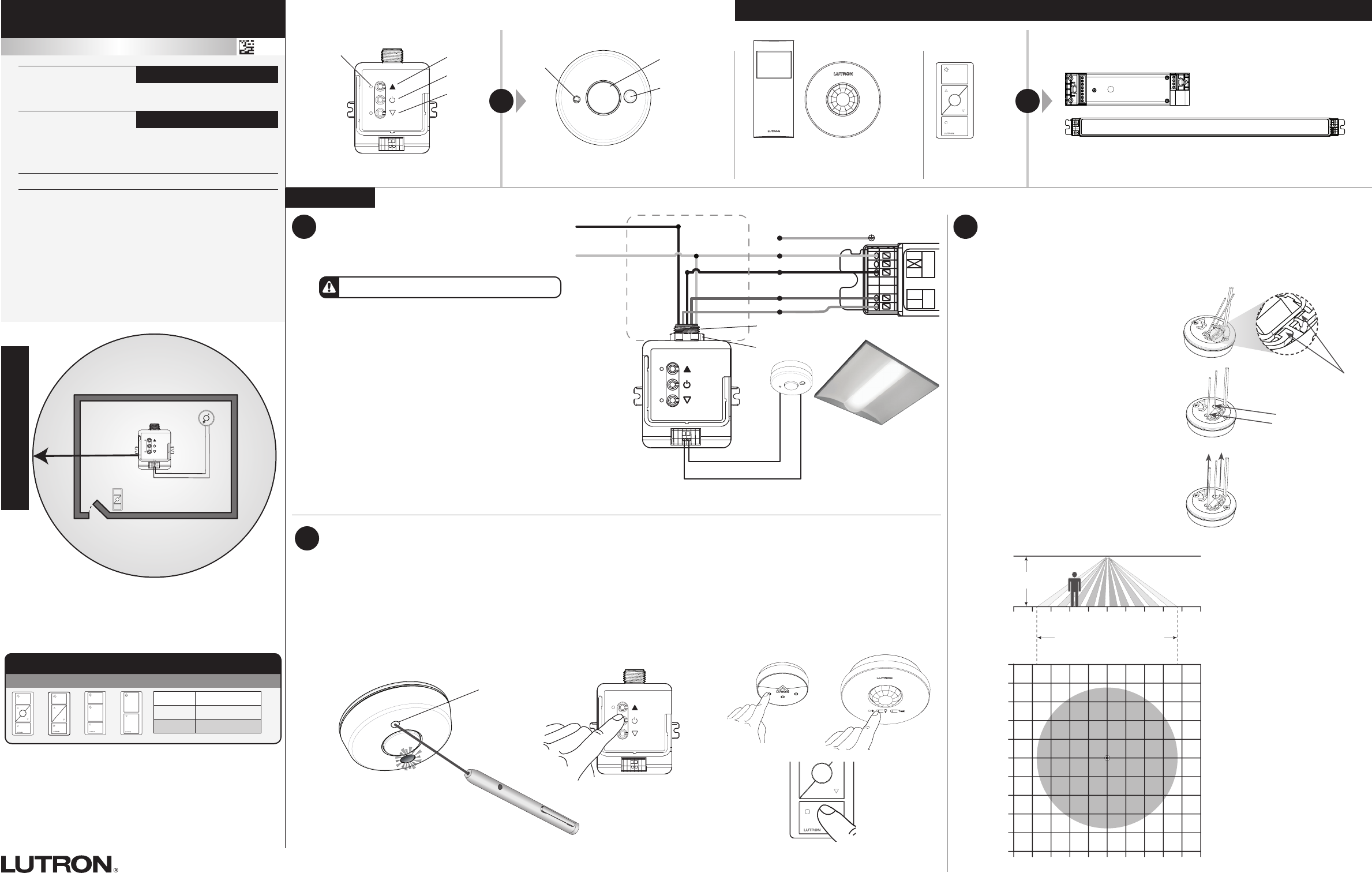
Initiate association mode on the Project 37 Control Module by shining a green
laser pointer at the laser detection hole on the sensor until the load attached to
the Project 37 Control Module starts flashing every 2 seconds.
Alternatively, press and hold the toggle button for 6 seconds on the Project 37
Control Module to initiate association mode.
3
OR
Laser Detection (smallest)
Associate Wireless Transmitters to Project 37 Control Module
Before beginning this step, make sure that there are no other Project 37 Control Modules being set up in the building which are currently in this
association mode.. It is possible that wireless transmitters from other systems can be incorrectly associated to this module.
Green laser specifications:
• Wave output: constant
• Wavelength: 532 nm
• Output power: 5 mW maximum
Technical Assistance | 1.800.523.9466 USA, Canada, and the Caribbean | +44.(0)20.7702.0657 Europe | +1.610.282.3800 Others | www.lutron.com
041467
Rev. A
07/2014
Part of the Energi TriPak® Family
Project 37 | Installation
+
For each fixture, ensure that you have:
One Project 37 Control Module At least one Sensor or Pico® Wireless Control At least one 0 – 10 V Fluorescent Ballast or LED Driver
Required Components
Project 37 Occupancy/Vacancy and
Daylight Sensor (1 maximum)
Pico® Wireless
Control
(10 maximum)
6 mA maximum for the control lines. Switches up to 1 A total. May be
pre-installed in light fixture.
Project 37 Control Module with 0 –10 V
Raise
Toggle
Lower
Load Status LED Consult third-party 0 – 10 V fixtures installation guide for fixture-specific wiring.
Start Here
+
Wireless Controls
On All lights 100%
Favorite All lights 50%
Off All lights off
Default Functionality
English
All Wireless
Transmitters
must be
installed within
30 ft (9 m) of the
Project 37 Control Module.
Control: 0–10 V- 6 mA
Important Notes: Please read before installing.
For installation by a qualified electrician in accordance with all
local and national electrical codes.
• Note: Use copper conductors only.
• Check to see that the device type and rating is suitable for the
application.
• DO NOT install if product has any visible damage.
• If moisture or condensation is evident, allow the product to dry
completely before installation.
• Operate between 0 °C and 40 °C, ambient.
• 0% to 90% humidity, non-condensing.
• For indoor use only.
120 – 277 V~ 50 / 60 Hz 1 A
FC-1 (Project 37
Control Module)
UL 2043 Plenum Rated
12 V- 25 mA
FC-0
(Project 37 Sensor)
Sensor
Pico®
Wireless
Control
Project 37
Control
Module
30 ft (9 m) max
40 ft (12 m)
30 ft (9 m)
Project 37
Control Module
1
PIR Lens
Laser Detection
Daylight Lens
Note: Project 37 Control Module can be used without a Sensor
Install control module directly to fixture or
in junction box nearest the fixture. Install sensor
in ceiling near fixture so as to optimize cover-
age in the desired area.
Radio Powr SavrTM
Occupancy/Vacancy Sensor
(10 maximum)
Install Project 37 Control Module
and Sensor
Suggested Installation Location: Close to the
Fixture/Troffer.
The Project 37 Control Module can be installed in a
fixture/troffer, junction box or marshalling box using the
conduit nut (provided) or with mounting screws (not
provided). Please consult local and national electric
codes for proper installation.
If installing unit inside a junction box, please see
Application Note #423 at
www.lutron.com/TechnicalDocumentLibrary/048423.pdf
B
Ideally mount the sensor to the ceiling tile close to the
fixture using the wire form or using the command strips
(included). The 2 communication wires from the sensor
attaches to the control module poke in connectors.
C
Once installed, energize the Project 37 Control Module.
Green/Yellow
Neutral
Switched
Hot/Live
Violet
Gray
Fixture Earth
+
–
To additional 0 – 10 V fixtures
Hot (Black)
Neutral
+
–
NEU
HOT
Class 2
MAINS
+
–
NEU
HOT
Class 2
MAINS
Switched Hot (Red)
Hot (Black)
Neutral (White)
Neutral
Fixture/Troffer
or Junction
Box 1/2 in (21 mm) Knockout Opening
Conduit Nut
From back of sensor
Violet
Gray
Fixture Earth
Green/Yellow
WARNING! Shock Hazard. May result in serious injury or death.
Turn off power at circuit breaker before installing the unit.
Spring arms
Note: For solid ceilings or
others where the wireform
cannot be utilized, use the
supplied Command strips
to adhere sensor to desired
location on ceiling or fixture.
Sensor Detection Range
2Install the Sensor
The Project 37 sensor mounts to the ceiling surface with a supplied wireform clip.
Two wires connect to the control module and can either be routed through a hole in
the ceiling or across the ceiling surface. DO NOT install on ceilings higher than 12 ft
(3.7 m). The sensor should be installed in a location where it has a good view of the
space that it is meant to cover.
15 ft
(4.6 m) 9 ft
(2.7 m) 3 ft
(0.9 m) 03 ft
(0.9 m) 9 ft
(2.7 m) 15 ft
(4.6 m)
400 ft2 (37 m2) maximum coverage
area of one sensor when mounted
on an 9 ft (2.75 m) ceiling
Ceiling
Floor
9 ft
(2.75 m)
15 ft
(4.6 m)
9 ft
(2.7 m)
3 ft
(0.9 m)
0
3 ft
(0.9 m)
9 ft
(2.7 m)
15 ft
(4.6 m)
15 ft
(4.6 m) 9 ft
(2.7 m) 3 ft
(0.9 m) 03 ft
(0.9 m) 9 ft
(2.7 m) 15 ft
(4.6 m)
A
Slide closed end of wire form under
the two retention arms on the back
of the sensor
B
While continuing to push against the
retention arms, rock the other side of
the wireform down against the sensor
and slide them into place under the
loop retention features
C
Push wireform through tile and
bend on the backside of the tile to
complete the mounting.
041467
Rev. A
07/2014
Part of the Energi TriPakR Family
Project 37 Load Control Module |
Programming
ALL PROGRAMMING IS OPTIONAL
Programming is not required for default functionality
• Set a favorite light level
• Set high-end and low-end trim for all fixtures
Lutron Electronics Co., Inc., 7200 Suter Road
Coopersburg, PA 18036-1299 U.S.A.
Limited Warranty
Lutron EA Ltd. (“Lutron EA”) warrants each unit to be free from
defects in material and workmanship and to perform under
normal use and service. To the extent permitted by law, Lutron
EA and Lutron Electronics Co. Inc. (“Lutron”) make no warranties
or representations as to the units except as set forth herein. This
warranty shall run for a period of two years from the date of purchase
and Lutron’s obligations under this warranty are limited to remedying
any defect, replacing any defective part or replacement (at Lutron
EA’s sole option) and shall be effective only if the defective unit
is shipped to Lutron EA postage prepaid within 24 months after
purchase of the unit. Repair or replacement of the unit does not affect
the expiry date of the warranty. This warranty does not cover damage
or deficiencies due to abuse, misuse, inadequate wiring or insulation
or use or installation other than in accordance with instructions
accompanying the unit.
To the extent permitted by law, neither Lutron EA nor Lutron shall be
liable for any other loss or damage including consequential or special
loss or damages, loss of profits, loss of income, or loss of contracts
arising out of or relating to the supply of the unit or the use of the unit
and the purchaser assumes and will hold harmless Lutron EA and
Lutron in respect of all such loss or damage. Nothing in this warranty
shall have the effect of limiting or excluding Lutron EA’s or Lutron’s
liability for fraud or for death or personal injury resulting from its own
negligence, or any other liability, if and to the extent that the same
may not be limited or excluded as a matter of law.
This warranty does not affect the statutory rights of consumer
purchasers of this product.
Although every attempt is made to ensure that catalogue information
is accurate and up-to-date, please check with Lutron EA before
specifying or purchasing this equipment to confirm availability, exact
specifications, and suitability for your application.
For information on other products, please see the Warranty
enclosed with the product.
Lutron, Pico, PowPak, Energi TriPak, Clear Connect, EcoSystem,
and ) are registered trademarks and Radio Powr Savr is a
trademark of Lutron Electronics Co., Inc.
©2014 Lutron Electronics Co., Inc.
Reset Factory Defaults
Note: In some instances, it may be necessary
to reset the PowPak® Dimming Module and
connected devices back to factory default
settings. Before beginning, make sure that all
devices are connected and powered.
A
Triple-tap any button on the PowPak® Dimming
Module and hold until the LED begins to flash
slowly; release button.
B
Within 3 seconds of the start of flashing, triple-tap
the same button again and the LEDs will flash
rapidly indicating that the unit has been reset to
factory defaults.
Note: Any associations or programming
previously set up with the PowPak® will be erased
and will need to be re-programmed.
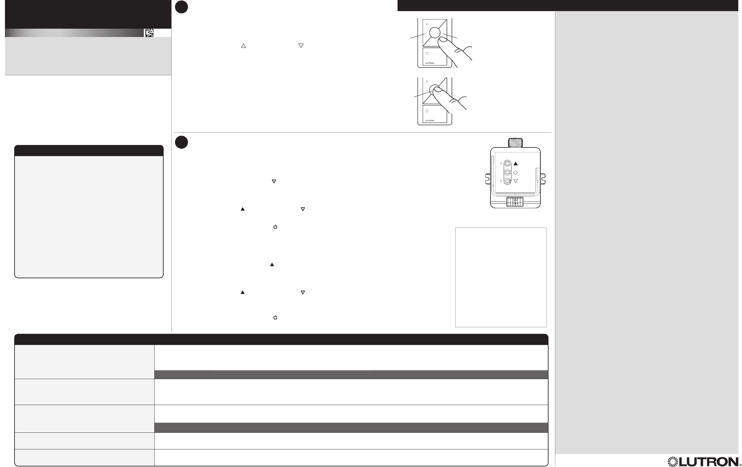
5Set Low-End and High-End Trim
For best results, minimize the amount of sunlight entering the room before performing the following procedures.
Low-End Trim
A
Enter low-end trim adjustment mode:
Press and hold Lower button “ ” for 12 seconds.
Lights will flash high-low-high and LED will begin flashing.
B
Adjust the low-end trim:
Use Raise button “ ” and Lower button “ ” to adjust and set the lights to the desired low-end (1to 45%).
C
Save the low-end trim:
Press and hold Toggle button “ ” for 6seconds to save setting.
LED will begin flashing and then turn solid to indicate new level has been saved.
High-End Trim
D
Enter high-end trim adjustment mode:
Press and hold Raise button “ ” for 12seconds.
Lights will flash high-low-high and LED will flash.
E
Adjust the high-end trim:
Use Raise button “ ” and Lower button “ ” to adjust and set the lights to the desired high-end
(55to 100%).
F
Save the high-end trim:
Press and hold Toggle button “ ” for 6seconds to save setting.
LED will begin flashing and then turn solid to indicate new level has been
Notes
Depending on the fixture
manufacturer or load, low-end
and high-end trim may need to
be adjusted.
• Trim low-end to ensure a stable
light level because some loads
will flicker or drop out if trimmed
too low.
• Be sure that you can turn on the
lights to the low-end trim level
without any abnormal operation.
• The factory default high-end trim
will normally be sufficient for most
applications. Trim as desired.
4
Raise Lower
Favorite
Troubleshooting www.lutron.com
Ballasts cannot be controlled locally from
PowPak® Dimming Module.
• Ensure that the breaker(s) to the PowPak® Dimming Module are energized.
• Ensure that the PowPak® Dimming Module switched hot lead is wired to the ballast(s).
• Ensure that the PowPak® Dimming Module 0 –10 V control lines are wired to the ballast(s).
Reset to factory defaults.
Lights do not dim or turn ON as expected. • Ensure that 0 –10 V control lines are wired properly.
• Ensure that fixture does not require an inverted signal (10 – 0 V control).
• Ensure that the wires are connected between the Project 37 Sensor and Project 37 Control Module
Lights do not respond to Wireless Transmitter(s). • Ensure that the breaker(s) to the PowPak® Dimming Module and ballasts are energized.
• Ensure that Wireless Transmitters are associated to the PowPak® Dimming Module.
Reset to factory defaults.
Lights are unstable at low-end or flash/flicker at
turn-on or turn-off.
• Adjust low-end trim.
Wireless Transmitter(s) cannot be associated to
PowPak® Dimming Module.
• The maximum number of Wireless Transmitters have been associated to the PowPak® Dimming Module. To remove a previously set up Wireless
Transmitter, tap a Wireless Transmitter button three times; on the third tap hold for three seconds and then tap three more times.
FCC Information (FC-0, FC-1 and FC-2 only)
This device complies with part 15 of the FCC Rules and Industry
Canada license-exempt RSS standard(s). Operation is subject
to the following two conditions: (1) This device may not cause
interference, and (2) this device must accept any interference,
including interference that may cause undesired operation.
Modifications not expressly approved by Lutron Electronics Co.,
Inc. could void the user’s authority to operate this equipment.
NOTE: This equipment has been tested and found to comply
with the limits for a Class B digital device, pursuant to part
15 of the FCC Rules. These limits are designed to provide
reasonable protection against harmful interference in a residential
installation. This equipment generates, uses and can radiate radio
frequency energy and, if not installed and used in accordance
with the instructions, may cause harmful interference to radio
communications. However, there is no guarantee that interference
will not occur in a particular installation. If this equipment does
cause harmful interference to radio or television reception, which
can be determined by turning the equipment off and on, the user is
encouraged to try to correct the interference by one or more of the
following measures:
• Re-orient or relocate the receiving antenna.
• Increase the separation between the equipment and receiver.
• Connect the equipment into an outlet on a circuit different from
that to which the receiver is connected.
Set a Favorite Light Level
For Pico® Wireless Controls with a Favorite Button.
A
Adjust lights to desired level:
Use Raise button “ ” or Lower button “ ” on Pico® wireless control.
B
Save favorite level:
Press and hold Favorite button for 6seconds.
The load flashes 3 times to confirm that the set level is saved.
Technical Assistance | 1.800.523.9466 USA, Canada, and the Caribbean | +44.(0)20.7702.0657 Europe | +1.610.282.3800 Others | www.lutron.com