Lyngsoe Systems MC30RG RFID PORTAL FOR POSTAL/DELIVERY TRACKING User Manual
Lyngsoe Systems Ltd. RFID PORTAL FOR POSTAL/DELIVERY TRACKING Users Manual
UserManual.wiki
>
Lyngsoe Systems
>
MC30RG User Manual
Users Manual
Navigation menu
Upload a User Manual
Namespaces
Wiki Guide
HTML
PDF
Info
Views
User Manual
Discussion / Help
Navigation
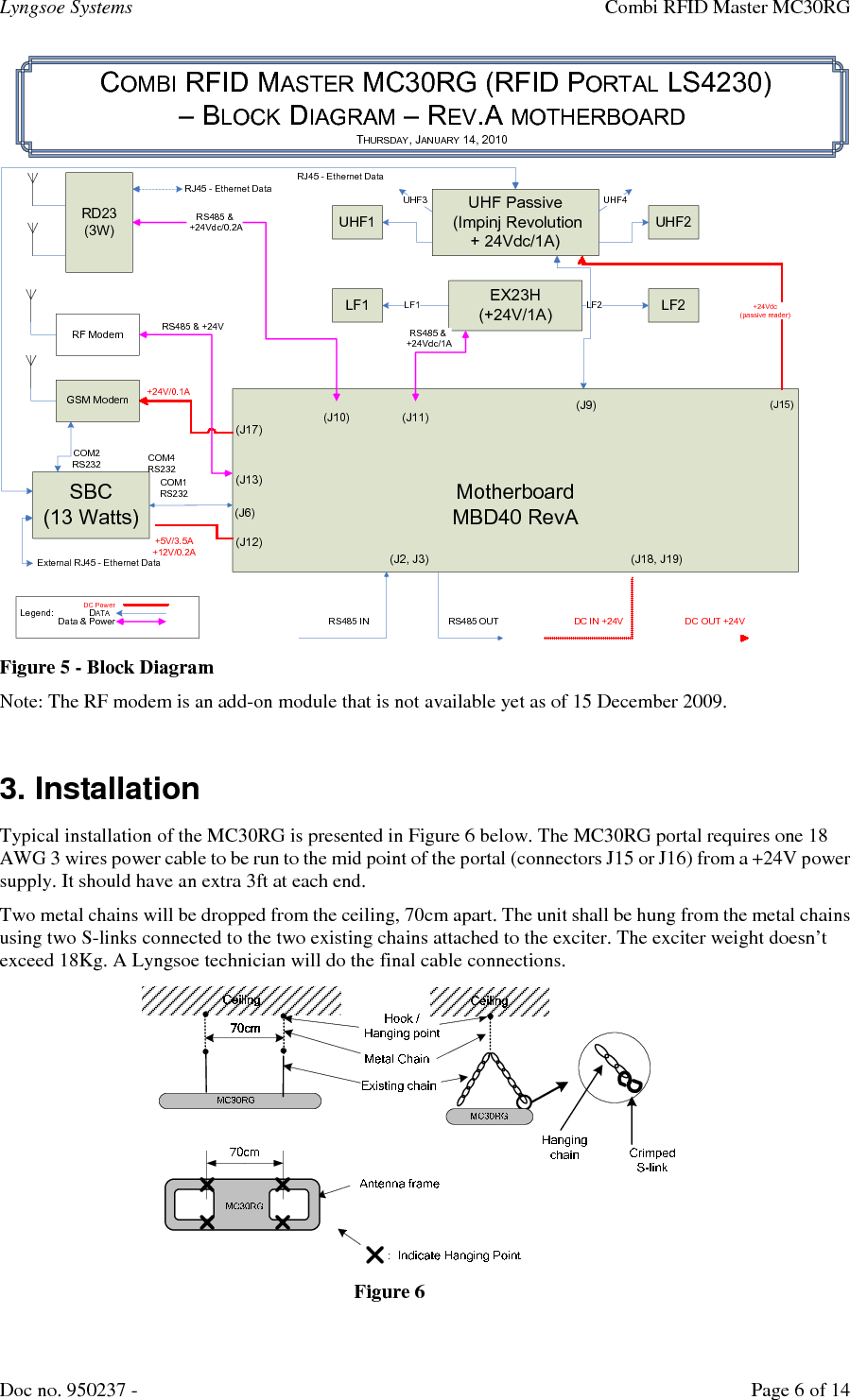
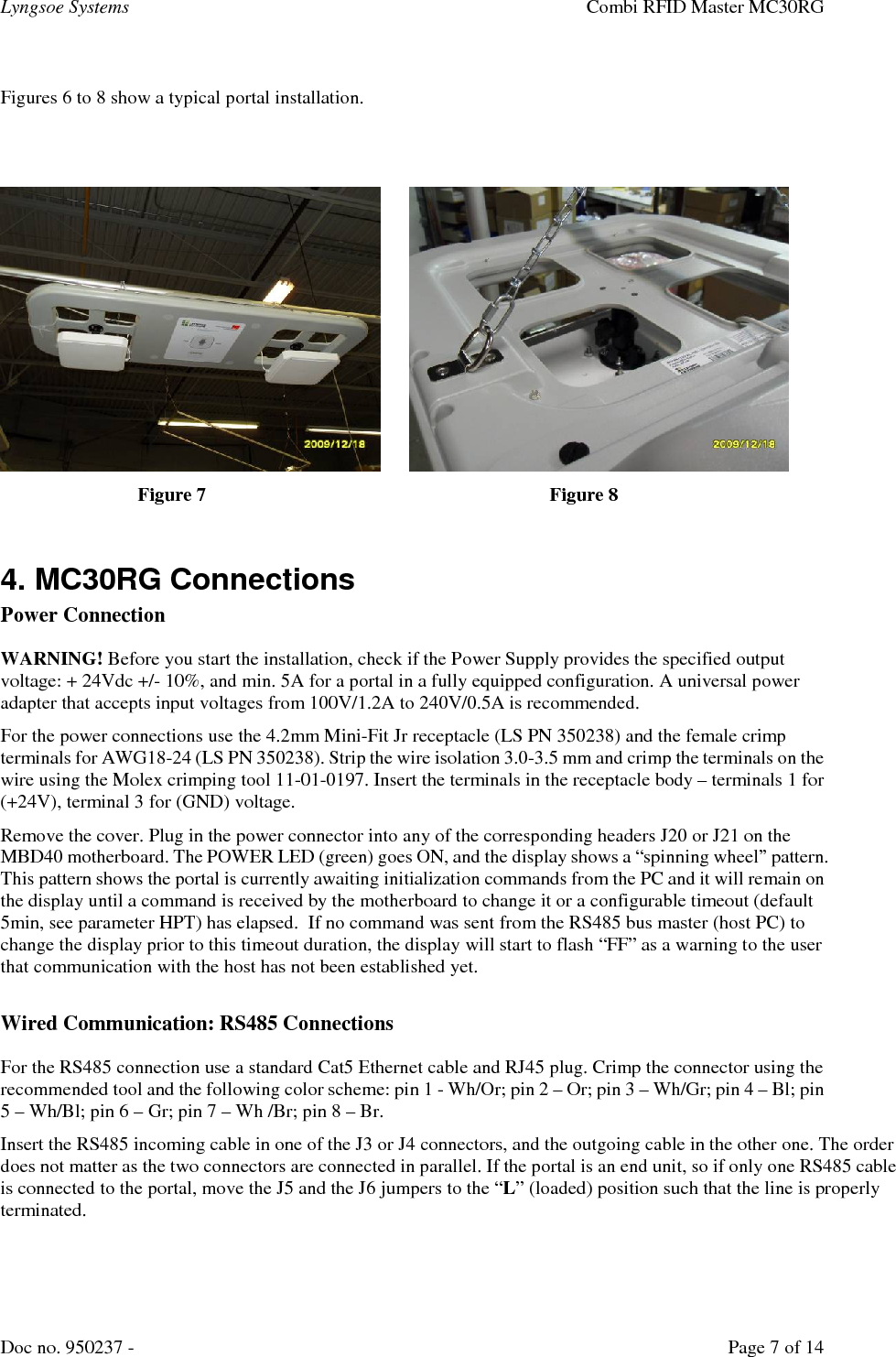
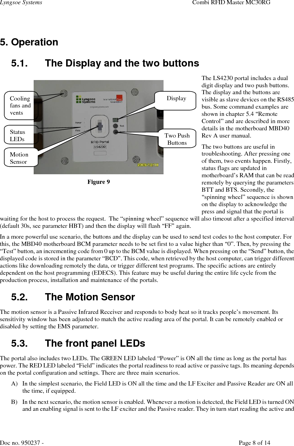
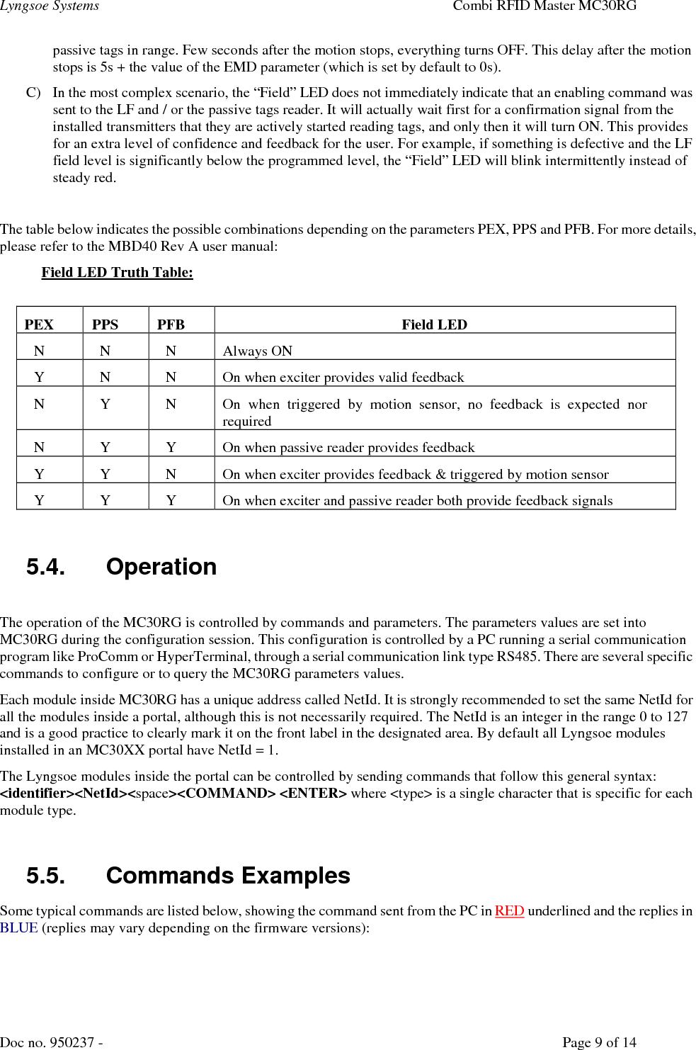
![Lyngsoe Systems Combi RFID Master MC30RG Doc no. 950237 - Page 5 of 14 1. Impinj Speedway Revolution passive reader (Part no IPJ-REV-R440-EU11M1 for Europe and IPJ-REV-R440-USA1M for North America) with two or four antennas (can be band specific EU or USA, or dual band antennas that work on both frequencies), compatible with ISO 18000-6C & EPCglobal UHF Class 1 Gen 2 protocols 2. motherboard MBD40 Rev A that provides mechanical support, power and data communication to all other subassemblies and modules. 3. RFID Exciter EXB40 that generates a 125 kHz excitation field for Lyngsoe active tags. In the pictures below you can see an example of Lyngsoe Active RFID tag model PT23. The EXB40 board also includes the 434MHz transmitter circuitry of an active tag in order to generate self-test messages. 4. receiver RD23 on 434MHz that receives the replies from the active tags PT23, PT30 etc. 5. Single Board Computer (SBC) from Axiomtek – Part no. SBC84620 6. GSM / GPRS Quad band modem from TMAS – Part no. TMA-M55i 7. 2.4 GHz RF modem (ZigBee) from Digi (MaxStream) – part no. XBP24-DMCIT-250J For the included subassemblies, details and technical specifications are completely described by the following documents that are part of this user manual (document name in italics): General: RFID System S23, Reference Guide – S23ReferenceGuide.pdf; Motherboard: Motherboard MBD40 Rev A - User Manual.pdf 125KHz / 434 MHz transmitter: Exciter EXB40 - Functional Specification.pdf; 434MHz receiver (RFID Reader RD23), User Guide – RD23 User Guide 950214.pdf UHF Gen2 Passive reader: Speedway Revolution Installation and Operations Guide.pdf Single Board Computer: SBC84620 User Manual VA3_2-1-2008.pdf GSM modem: Documents tmas_gprs_modem_setup_guide_for_internet[1].pdf and tmas_modem_hardware_user_manual[1].pdf](https://usermanual.wiki/Lyngsoe-Systems/MC30RG/User-Guide-1241482-Page-5.png)