Lyngsoe Systems MC30RG RFID PORTAL FOR POSTAL/DELIVERY TRACKING User Manual
Lyngsoe Systems Ltd. RFID PORTAL FOR POSTAL/DELIVERY TRACKING Users Manual
Users Manual

Lyngsoe Systems Combi RFID Master MC30RG
Doc no. 950237 - Page 1 of 14
Combi RFID Master
MC30RG (LS 4230)
User Guide
Revision A
January 2010
Lyngsoe Systems Combi RFID Master MC30RG
Doc no. 950237 - Page 2 of 14
1.
General.................................................................................................................................................. 3
2.
MC30RG Description ........................................................................................................................... 3
3.
Installation ............................................................................................................................................ 6
4.
MC30RG Connections.......................................................................................................................... 7
5.
Operation .............................................................................................................................................. 8
5.1.
The Display and the two buttons...................................................................................................... 8
5.2.
The Motion Sensor........................................................................................................................... 8
5.3.
The front panel LEDs....................................................................................................................... 8
5.4.
Operation.......................................................................................................................................... 9
5.5.
Commands Examples....................................................................................................................... 9
5.5.1.
Receiver commands ....................................................................................................................... 10
5.5.2.
Exciter commands.......................................................................................................................... 10
5.5.3.
Motherboard commands................................................................................................................. 11
5.5.4.
Passive tags reader (UHF EPCglobal Gen2 compatible) commands ............................................. 12
5.6.
Other commands ............................................................................................................................ 12
6.
FCC compliance ................................................................................................................................. 13
7.
Appendix 1 – Active and Passive RFID Tags Examples .................................................................... 14
Lyngsoe Systems Combi RFID Master MC30RG
Doc no. 950237 - Page 3 of 14
1. General
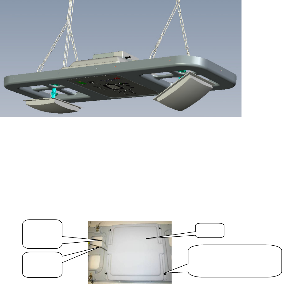
Combi RFID Master MC30RG is a combined unit that can operate completely independent as an RFID Portal
that is able to read RFID active tags on 125 kHz/434MHz as well as passive tags on 868/915MHz (see
Appendix 1 for active and passive tags examples). After reading, the incorporated Single Board Computer
(SBC) can filter the relevant readings and can report them over a wireless GSM / GPRS link to a central
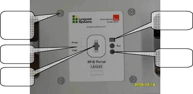
database for processing. The marketing name for MC30RG is LS4230 – this name is printed on the front
label.
Figure 1 - General view
2. MC30RG Description
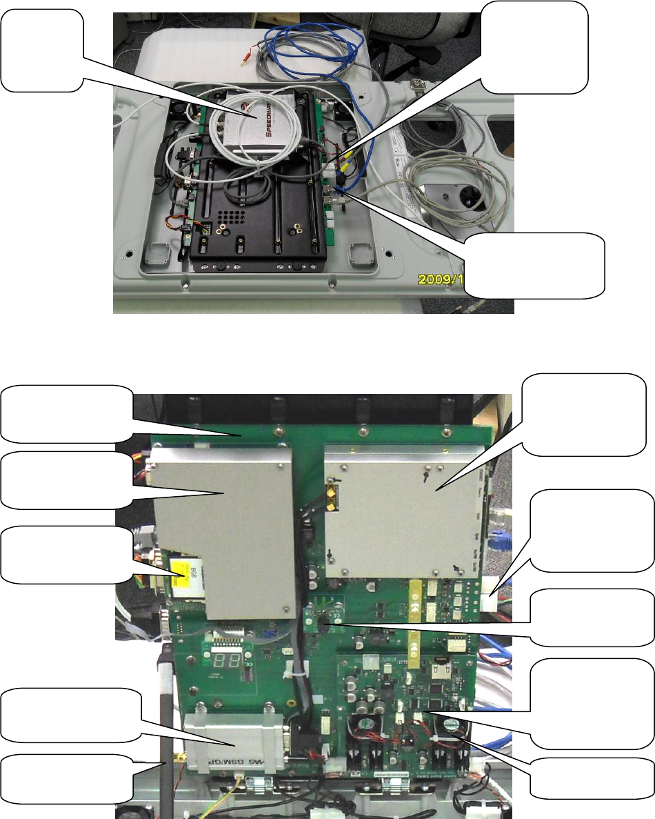
On the top side of the MC30RG portal there is a cover that needs to be removed in order to connect the unit to
power and wired RS485 communication lines. Place the portal on a flat surface with the cover up. If the
passive antennas are installed, it is recommended to place the portal transversal on a narrower work table
with the top cover up such that the two passive antennas hang in the open space.
Remove the plastic quarter-turn screws and lift the cover.
Figure 2 - Cover removal for MC30RG
Remove the four plastic screws
using a coin or a flat screwdriver
10-20mm wide.
Cover
Power
Cable
RS485
Cable
Lyngsoe Systems Combi RFID Master MC30RG
Doc no. 950237 - Page 4 of 14
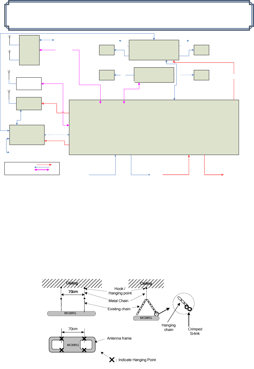
As it can be seen in the above block diagram and from Figure 3 and Figure 4 below, the MC30RG portal
integrates in the same enclosure the following modules and subassemblies:
Figure 3 – MC30RG inside view – tray closed
Figure 4 – MC30RG inside view – tray open
#2. MBD40
motherboard
#3. EXB40
Transmitter on
125kHz and
434MHz
#6. GSM / GPRS
QuadBand Modem
#4. 434MHz
Receiver RDS23
#5. Single Board
Computer (SBC)
Compact Flash
Card (EDECS)
Supporting arm
2 x Cooling Fans
Two RS485
communication
connectors
Two +24Vdc
Power
connectors
#1.
Passive
Tags
Reader
Internal Motion
Sensor
Two +24Vdc
Power
connectors
Lyngsoe Systems Combi RFID Master MC30RG
Doc no. 950237 - Page 5 of 14
1. Impinj Speedway Revolution passive reader (Part no IPJ-REV-R440-EU11M1 for Europe and
IPJ-REV-R440-USA1M for North America) with two or four antennas (can be band specific EU or
USA, or dual band antennas that work on both frequencies), compatible with ISO 18000-6C &
EPCglobal UHF Class 1 Gen 2 protocols
2. motherboard MBD40 Rev A that provides mechanical support, power and data communication to
all other subassemblies and modules.
3. RFID Exciter EXB40 that generates a 125 kHz excitation field for Lyngsoe active tags. In the
pictures below you can see an example of Lyngsoe Active RFID tag model PT23. The EXB40 board
also includes the 434MHz transmitter circuitry of an active tag in order to generate self-test
messages.
4. receiver RD23 on 434MHz that receives the replies from the active tags PT23, PT30 etc.
5. Single Board Computer (SBC) from Axiomtek – Part no. SBC84620
6. GSM / GPRS Quad band modem from TMAS – Part no. TMA-M55i
7. 2.4 GHz RF modem (ZigBee) from Digi (MaxStream) – part no. XBP24-DMCIT-250J
For the included subassemblies, details and technical specifications are completely described by the
following documents that are part of this user manual (document name in italics):
General: RFID System S23, Reference Guide – S23ReferenceGuide.pdf;
Motherboard: Motherboard MBD40 Rev A - User Manual.pdf
125KHz / 434 MHz transmitter: Exciter EXB40 - Functional Specification.pdf;
434MHz receiver (RFID Reader RD23), User Guide – RD23 User Guide 950214.pdf
UHF Gen2 Passive reader: Speedway Revolution Installation and Operations Guide.pdf
Single Board Computer: SBC84620 User Manual VA3_2-1-2008.pdf
GSM modem: Documents tmas_gprs_modem_setup_guide_for_internet[1].pdf and
tmas_modem_hardware_user_manual[1].pdf
Lyngsoe Systems Combi RFID Master MC30RG
Doc no. 950237 - Page 6 of 14
Motherboard
MBD40 RevA
UHF Passive
(Impinj Revolution
+ 24Vdc/1A)
LF1
+5V/3.5A
+12V/0.2A
EX23H
(+24V/1A)
RS485 &
+24Vdc/1A
RS485 &
+24Vdc/0.2A
UHF4
UHF3
+24V/0.1A
COMBI RFID MASTER MC30RG (RFID PORTAL LS4230)
– BLOCK DIAGRAM – REV.A MOTHERBOARD
THURSDAY, JANUARY 14, 2010
(J6)
+24Vdc
(passive reader)
(J17)
(J12)
RF Modem RS485 & +24V
(J13)
GSM Modem
RD23
(3W)
SBC
(13 Watts)
COM1
RS232
COM2
RS232
UHF1 UHF2
LF1 LF2
LF2
(J15)
DC Power
DATA
Data & Power
Legend:
RJ45 - Ethernet Data
RJ45 - Ethernet Data
External RJ45 - Ethernet Data
COM4
RS232
(J9)
(J10) (J11)
DC IN +24V DC OUT +24VRS485 IN RS485 OUT
(J2, J3) (J18, J19)
Figure 5 - Block Diagram
Note: The RF modem is an add-on module that is not available yet as of 15 December 2009.
3. Installation
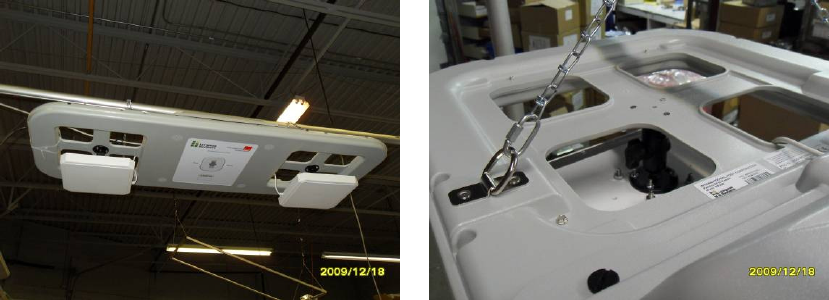
Typical installation of the MC30RG is presented in Figure 6 below. The MC30RG portal requires one 18
AWG 3 wires power cable to be run to the mid point of the portal (connectors J15 or J16) from a +24V power
supply. It should have an extra 3ft at each end.
Two metal chains will be dropped from the ceiling, 70cm apart. The unit shall be hung from the metal chains
using two S-links connected to the two existing chains attached to the exciter. The exciter weight doesn’t
exceed 18Kg. A Lyngsoe technician will do the final cable connections.
Figure 6
Lyngsoe Systems Combi RFID Master MC30RG
Doc no. 950237 - Page 7 of 14
Figures 6 to 8 show a typical portal installation.
Figure 7 Figure 8
4. MC30RG Connections
Power Connection
WARNING! Before you start the installation, check if the Power Supply provides the specified output
voltage: + 24Vdc +/- 10%, and min. 5A for a portal in a fully equipped configuration. A universal power
adapter that accepts input voltages from 100V/1.2A to 240V/0.5A is recommended.
For the power connections use the 4.2mm Mini-Fit Jr receptacle (LS PN 350238) and the female crimp
terminals for AWG18-24 (LS PN 350238). Strip the wire isolation 3.0-3.5 mm and crimp the terminals on the
wire using the Molex crimping tool 11-01-0197. Insert the terminals in the receptacle body – terminals 1 for
(+24V), terminal 3 for (GND) voltage.
Remove the cover. Plug in the power connector into any of the corresponding headers J20 or J21 on the
MBD40 motherboard. The POWER LED (green) goes ON, and the display shows a “spinning wheel” pattern.
This pattern shows the portal is currently awaiting initialization commands from the PC and it will remain on
the display until a command is received by the motherboard to change it or a configurable timeout (default
5min, see parameter HPT) has elapsed. If no command was sent from the RS485 bus master (host PC) to
change the display prior to this timeout duration, the display will start to flash “FF” as a warning to the user
that communication with the host has not been established yet.
Wired Communication: RS485 Connections
For the RS485 connection use a standard Cat5 Ethernet cable and RJ45 plug. Crimp the connector using the
recommended tool and the following color scheme: pin 1 - Wh/Or; pin 2 – Or; pin 3 – Wh/Gr; pin 4 – Bl; pin
5 – Wh/Bl; pin 6 – Gr; pin 7 – Wh /Br; pin 8 – Br.
Insert the RS485 incoming cable in one of the J3 or J4 connectors, and the outgoing cable in the other one. The order
does not matter as the two connectors are connected in parallel. If the portal is an end unit, so if only one RS485 cable
is connected to the portal, move the J5 and the J6 jumpers to the “L” (loaded) position such that the line is properly
terminated.
Lyngsoe Systems Combi RFID Master MC30RG
Doc no. 950237 - Page 8 of 14
5. Operation
5.1. The Display and the two buttons
The LS4230 portal includes a dual
digit display and two push buttons.
The display and the buttons are
visible as slave devices on the RS485
bus. Some command examples are
shown in chapter 5.4 “Remote
Control” and are described in more
details in the motherboard MBD40
Rev A user manual.
The two buttons are useful in
troubleshooting. After pressing one
of them, two events happen. Firstly,
status flags are updated in
motherboard’s RAM that can be read
remotely by querying the parameters
BTT and BTS. Secondly, the
“spinning wheel” sequence is shown
on the display to acknowledge the
press and signal that the portal is
waiting for the host to process the request. The “spinning wheel” sequence will also timeout after a specified interval
(default 30s, see parameter HBT) and then the display will flash “FF” again.
In a more powerful use scenario, the buttons and the display can be used to send test codes to the host computer. For
this, the MBD40 motherboard BCM parameter needs to be set first to a value higher than “0”. Then, by pressing the
“Test” button, an incrementing code from 0 up to the BCM value is displayed. When pressing on the “Send” button, the
displayed code is stored in the parameter “BCD”. This code, when retrieved by the host computer, can trigger different
actions like downloading remotely the data, or trigger different test programs. The specific actions are entirely
dependent on the host programming (EDECS). This feature may be useful during the entire life cycle from the
production process, installation and maintenance of the portals.
5.2. The Motion Sensor
The motion sensor is a Passive Infrared Receiver and responds to body heat so it tracks people’s movement. Its
sensitivity window has been adjusted to match the active reading area of the portal. It can be remotely enabled or
disabled by setting the EMS parameter.
5.3. The front panel LEDs
The portal also includes two LEDs. The GREEN LED labeled “Power” is ON all the time as long as the portal has
power. The RED LED labeled “Field” indicates the portal readiness to read active or passive tags. Its meaning depends
on the portal configuration and settings. There are three main scenarios.
A) In the simplest scenario, the Field LED is ON all the time and the LF Exciter and Passive Reader are ON all
the time, if equipped.
B) In the next scenario, the motion sensor is enabled. Whenever a motion is detected, the Field LED is turned ON
and an enabling signal is sent to the LF exciter and the Passive reader. They in turn start reading the active and
Figure 9
Cooling
fans and
vents
Status
LEDs
Two Push
Buttons
Display
Motion
S
ensor

Lyngsoe Systems Combi RFID Master MC30RG
Doc no. 950237 - Page 9 of 14
passive tags in range. Few seconds after the motion stops, everything turns OFF. This delay after the motion
stops is 5s + the value of the EMD parameter (which is set by default to 0s).
C) In the most complex scenario, the “Field” LED does not immediately indicate that an enabling command was
sent to the LF and / or the passive tags reader. It will actually wait first for a confirmation signal from the
installed transmitters that they are actively started reading tags, and only then it will turn ON. This provides
for an extra level of confidence and feedback for the user. For example, if something is defective and the LF
field level is significantly below the programmed level, the “Field” LED will blink intermittently instead of
steady red.
The table below indicates the possible combinations depending on the parameters PEX, PPS and PFB. For more details,
please refer to the MBD40 Rev A user manual:
Field LED Truth Table:
PEX PPS PFB Field LED
N N N Always ON
Y N N On when exciter provides valid feedback
N Y N On when triggered by motion sensor, no feedback is expected nor
required
N Y Y On when passive reader provides feedback
Y Y N On when exciter provides feedback & triggered by motion sensor
Y Y Y On when exciter and passive reader both provide feedback signals
5.4. Operation
The operation of the MC30RG is controlled by commands and parameters. The parameters values are set into
MC30RG during the configuration session. This configuration is controlled by a PC running a serial communication
program like ProComm or HyperTerminal, through a serial communication link type RS485. There are several specific
commands to configure or to query the MC30RG parameters values.
Each module inside MC30RG has a unique address called NetId. It is strongly recommended to set the same NetId for
all the modules inside a portal, although this is not necessarily required. The NetId is an integer in the range 0 to 127
and is a good practice to clearly mark it on the front label in the designated area. By default all Lyngsoe modules
installed in an MC30XX portal have NetId = 1.
The Lyngsoe modules inside the portal can be controlled by sending commands that follow this general syntax:
<identifier><NetId><space><COMMAND> <ENTER> where <type> is a single character that is specific for each
module type.
5.5. Commands Examples
Some typical commands are listed below, showing the command sent from the PC in RED underlined and the replies in
BLUE (replies may vary depending on the firmware versions):

Lyngsoe Systems Combi RFID Master MC30RG
Doc no. 950237 - Page 10 of 14
5.5.1. Receiver commands
Querying Firmware version in the 434MHz receiver (RD23):
@1 IVN
@1 OK
@1 IVN="RD23_V3.1.02, BUILT: May 19 2009 at 09:56:22"
Reading the first 5 tag records stored in the RD23:
@1 :Y 5
@1 {TS="0406151824Z",LI=-83,UD="\x11"3DU",EX="\xFF",CT="Z",FG="HI"}
@1 {TS="0406151824Z",LI=-71,UD="TR030",EX="\xFF",CT="Z",FG="HI"}
@1 {TS="0406151824Z",LI=-78,UD="TR036",EX="\xFF",CT="Z",FG="HI"}
@1 {TS="0406151824Z",LI=-72,UD="TR030",EX="\xFF",CT="Z",FG="HI"}
@1 {TS="0406151824Z",LI=-83,UD="C\xFD\x00W\xE0",EX="\xFF",CT="@",FG="HI"}
@1 05 ;Comment: this number varies, here it shows that 5 records were displayed
Finding out the total number of tag records from RD23:
@1 DMC
@1 OK
@1 DMC=163
Erasing all tag records from RD23:
@1 :DATA:PURGE
@1 OK
@1 00
5.5.2. Exciter commands
Querying Firmware version in the 125kHz transmitter – the Exciter EXB40 module:
#1 EVN
#1 EVN=0.2
#1 OK
Turning OFF the 125kHz field (after power up the field is ON):
#1 C
#1 OK

Lyngsoe Systems Combi RFID Master MC30RG
Doc no. 950237 - Page 11 of 14
Turning ON the 125kHz field:
#1 B
#1 OK
5.5.3. Motherboard commands
Querying Firmware version in the motherboard MBD40:
%1 IVN
%1 OK
%1 MBD40 RFID Portal Motherboard v2.0.9 Built 9-Sep-09
Displaying the hex value of a number on the 7-segment displays (from 00-FF). If “B” is specified the display will blink
on and off.
%1 DSP=05 B
%1 OK
%1 DSP=05 ;the display will blink “05”, on and off.
Querying the status of the “Test” or “Send” buttons:
%1 BTS
%1 OK
%1 BTS=Y ; Shows that the Send button was pressed at least once since the last reset. Must be cleared manually
after reading by sending the “BTS=N” command or “:RESET”. Use BTT for the “Test” button.
Disconnecting the power for the active equipment (RD23, EX23) for 10 seconds:
%1 CSD
%1 OK
%1 00 ; waits for 10secs before re-applying power, then replies 00.
Disconnecting the power to the Single Board Computer for 10 seconds:
%1 CPC
%1 OK
%1 00 ; waits for 10secs before re-applying power, then replies 00.
Disconnecting the power to the GSM modem for 10 seconds:
%1 CGS
%1 OK
%1 00 ; waits for 10secs before re-applying power, then replies 00.

Lyngsoe Systems Combi RFID Master MC30RG
Doc no. 950237 - Page 12 of 14
Disabling the motion sensor in the motherboard MBD40 (default , LF and UHF readers are ON all the time):
%1 EMS=N
%1 OK
%1 EMS=N
Enabling the motion sensor:
%1 EMS=Y
%1 OK
%1 EMS=Y
5.5.4. Passive tags reader (UHF EPCglobal Gen2
compatible) commands
The passive reader has two connections, one for power +24Vdc internal to the portal and one Ethernet connection to a
computer (internal or external to the portal). For more details referring the passive reader operation, please refer to the
user manual for the Impinj Speedway Revolution Reader. Part no for EU version of the reader is
IPJ-REV-R420-EU11M1 while for the North American version is IPJ-REV-R420-USA1M1.
The portal includes the capability to turn on and off tag scanning on the passive reader based on the internal motion
sensor. This feature helps minimize the potential interference between adjacent gates in a larger deployment and saves
power.
5.6. Other commands
For the complete list of commands and parameters accepted by the Portal, see the documentation for each module:
• the motherboard MBD40
• the LF Exciter EXB40
• the 434MHz reader RD23
• the Impinj Speedway Revolution reader - compatible with the EPCglobal or ISO18000-6 standards
• the GSM / GPRS modem
Lyngsoe Systems Combi RFID Master MC30RG
Doc no. 950237 - Page 13 of 14
6. FCC compliance
Caution:
Changes or modifications not expressly approved by the party responsible for compliance could void the user’s
authority to operate the equipment.
Part 15.105 Information to the user
NOTE: This equipment has been tested and found to comply with the limits for a Class B digital device, pursuant to
part 15 of the FCC Rules. These limits are designed to provide reasonable protection against harmful interference in a
residential installation. This equipment generates, uses, and can radiate radio frequency energy and, if not installed and
used in accordance with the instructions, may cause harmful interference to radio communications. However, there is
no guarantee that interference will not occur in a particular installation. If this equipment does cause harmful
interference to radio or television reception, which can be determined by turning the equipment off and on, the user is
encouraged to try to correct the interference by one or more of the following measures:
—Reorient or relocate the receiving antenna.
—Increase the separation between the equipment and receiver.
—Connect the equipment into an outlet on a circuit different from that to which the receiver is connected.
—Consult the dealer or an experienced radio/TV technician for help.
Lyngsoe Systems Combi RFID Master MC30RG
Doc no. 950237 - Page 14 of 14
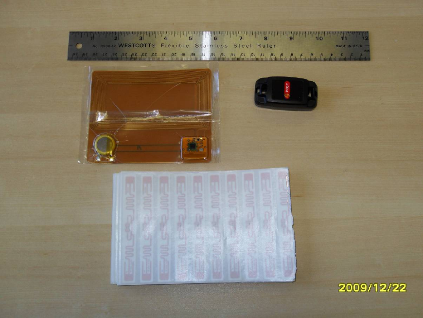
7. Appendix 1 – Active and Passive RFID Tags Examples
Top left – PT30 – active RFID tag used in postal services
Top right – CT23 – active RFID tag used to track roll-cages and containers
Bottom – several Alien “Squiggle” passive RFID tags, ready to peel and apply
Figure 10 – Active and Passive RFID tags