Lytx QCA6134 DC-6000-001 User Manual Repairing the ER SV2 Bracket
Lytx, Inc. DC-6000-001 Repairing the ER SV2 Bracket
Lytx >
User Manual

Lytx ER-SF1 Event Recorder
Installation Instructions
J1939 Network
Last Updated: March 10, 2017
Only a properly qualified technician should install and maintain the ER-SF1. Any electrical work should be performed only by an ASE (minimum T6
& L2), MECP or equivalent certified technician with an expertise in installing and troubleshooting advanced vehicle onboard components including
multiplexed circuits. Lytx, Inc. disclaims all responsibility for any damages arising from improper installation and maintenance of the ER-SF1.
© 2017 Lytx, Inc. – Confidential & Proprietary – For Velociti’s Use Only Re Beta ER-SF1 Installations
This guide is protected as confidential and proprietary information of Lytx, Inc. Copying and use of this guide for any purpose other than
installing ER-SF1 in vehicles of Lytx, Inc.’s customers is expressly prohibited. Information contained in this guide was in effect as of the date set
forth above and is subject to change without notice or liability. Lytx, Inc. reserves the right to revise the information presented or to discontinue
the production of parts described at any time.

ER-SF1 Event Recorder with J1939 Network Instructions for Self Installation
© 2017 Lytx, Inc. – Confidential & Proprietary – For Velociti’s Use Only Re Beta ER-SF1 Installations. Page 1 of 26
CONTENTS
Safety Instructions ..................................................................................................................................... 3
Installation Safety Warnings....................................................................................................................... 3
Driver Safety Warnings ............................................................................................................................... 3
Adherence to Applicable Local, State and Federal Laws ....................................................................... 4
USA Federal Communications Commission (FCC) Notice ...................................................................... 5
Canada – Industry Canada Notice ............................................................................................................. 5
Exposure of Humans to RF Fields.............................................................................................................. 5
Australia & New Zealand – Wireless Notice ............................................................................................. 6
Europe – R&TTE Directive 99/5/EC, Wireless Notice ............................................................................... 6
International Restrictions ........................................................................................................................... 6
Declaration of Conformity .......................................................................................................................... 6
Suppliers Declaration of Conformance .................................................................................................... 8
Device Installation Overview .......................................................................................................................... 8
What’s Covered in the Installation Procedures ....................................................................................... 8
Installation Warnings .................................................................................................................................. 8
Before You Begin ......................................................................................................................................... 9
Additional Support and Product Info ........................................................................................................ 9
Materials ....................................................................................................................................................... 9
Required Tools ........................................................................................................................................... 10
Optional Tools ............................................................................................................................................ 11
Installation Procedures ................................................................................................................................. 11
Mount the Bracket and Event Recorder ................................................................................................. 11
Mounting Location Guidelines ............................................................................................................. 12
Clean and Dry the Windshield.............................................................................................................. 13
Mark the Mounting Location on the Glass ......................................................................................... 14
Attach the Bracket to the Windshield ................................................................................................. 14

ER-SF1 Event Recorder with J1939 Network Instructions for Self Installation
© 2017 Lytx, Inc. – Confidential & Proprietary – For Velociti’s Use Only Re Beta ER-SF1 Installations. Page 2 of 26
Mount the Event Recorder in the Bracket .......................................................................................... 15
Connect Electrical Wiring .......................................................................................................................... 16
Wiring Safety Warnings ......................................................................................................................... 16
Electrical Connection Overview Diagram ........................................................................................... 17
Wiring and Wire Termination Suggestions ......................................................................................... 18
Basic Event Recorder Electrical Connections ..................................................................................... 19
Connect to the J1939 Bus Interface ..................................................................................................... 20
Route the ER Cable ................................................................................................................................ 21
Run Testing and Complete Installation .................................................................................................. 23
Boot Up the ER and Test Event Creation ............................................................................................ 23
Test Wire Connections and Settings in the Lytx Installation Tool ................................................... 23
Complete Installation ............................................................................................................................ 23
Final Checks ............................................................................................................................................ 24
Troubleshooting & Maintenance................................................................................................................. 25
Contact Technical Support ....................................................................................................................... 25

ER-SF1 Event Recorder with J1939 Network Instructions for Self Installation
© 2017 Lytx, Inc. – Confidential & Proprietary – For Velociti’s Use Only Re Beta ER-SF1 Installations. Page 3 of 26
SAFETY INSTRUCTIONS
Installation Safety Warnings
Read and follow the instructions and precautions in this guide and all documents
referenced in this guide when installing this device. Always refer to the vehicle manufacturer’s
service manual for proper installation and wiring of any aftermarket devices, including the ER-SF1.
Failure to do so may result in property damage and/or personal injury.
WARNING: Park the vehicle on a level surface before beginning any maintenance or
installation. Block the wheels to prevent the vehicle from moving. Never work under a vehicle
supported only by jacks as jacks can slip and fall over.
WARNING: All wires that carry electrical current must be fused. Failure to do so can lead
to serious personal injury and/or property damage. If any wires or cables containing fuses/fuse
boxes need to be cut or otherwise shortened, always be certain to replace such fuses/fuse boxes
or install new ones.
WARNING: Wire Protection: Take all necessary measures to protect all wire runs through a
metal surface with a grommet or other device and all wire runs outside the vehicle cab with a
loom. Always protect against wire fatigue and harness abrasion by properly attaching wires at
closely spaced intervals, while avoiding contact with sharp edges or doing anything else that might
result in exposed wires. All wires should be secured with tie wraps at least every two feet or less.
Do not overtighten any tie wraps.
EXPLOSION HAZARD: Do not disconnect equipment unless power has been removed or the area
is known to be non-hazardous.
WARNING: Substituting or supplementing components may impair suitability and
performance. If you are missing any components contact Lytx U.S. Technical Support Center at
866.910.0403 or email support@lytx.com.
WARNING: Wear safe eye protection to prevent serious eye injury when you perform
vehicle maintenance or service.
Driver Safety Warnings
WARNING: Seat belt warning: To reduce the potential danger of injuries, the driver and front
passenger must always be correctly seated with seat belts correctly fastened when operating the
vehicle.

ER-SF1 Event Recorder with J1939 Network Instructions for Self Installation
© 2017 Lytx, Inc. – Confidential & Proprietary – For Velociti’s Use Only Re Beta ER-SF1 Installations. Page 4 of 26
DISCLAIMER: The Lytx Event Recorder is a driver aid only, not a substitute for a safe,
conscientious driver. This device cannot compensate for a driver who is distracted, inattentive or
impaired by fatigue, drugs or alcohol. Whether or not the device is in use, it is always the
responsibility of the driver to take appropriate corrective action. The driver should never wait for
the device to provide a warning before taking measures to avoid an accident. Failure to do so can
result in serious personal injury or death or severe property damage.
Always, it is the driver’s responsibility to:
Use safe driving techniques
Exercise proper judgment
Maintain a safe speed and distance between vehicles
Take measures to avoid an accident
Comply with all applicable laws and regulations
WARNING: The Lytx Event Recorder may have limited to no functionality in certain
conditions, including inclement weather, low visibility, and certain road conditions (including poor
lane markings, construction zones, dirt roads, heavy or complicated traffic, and curvy and winding
roads.) Always keep the lens and view of the device unobstructed and properly calibrated so as
not to inhibit function. Driving in certain conditions or with any interference with the device can
result in false, few, or no warnings. The driver must always monitor traffic and surroundings and
take measures to avoid an accident; failure to do so can result in serious personal injury or death
or severe property damage.
WARNING: Whether or not the Lytx Event Recorder is functioning, it is the driver’s
responsibility to maintain vehicle control; failure to do so can result in serious personal injury
or death or severe property damage. If the device is not functioning properly at any time, the
driver should contact their supervisor to have the device inspected immediately to correct the
issue.
Adherence to Applicable Local, State and Federal Laws
WARNING: Some jurisdictions have adopted, or may in the future adopt, laws that prohibit
objects from being mounted on a vehicle’s windshield or other locations in a vehicle. You are
responsible for complying with such laws, and Lytx, Inc. does not accept responsibility for your
failure to do so.

ER-SF1 Event Recorder with J1939 Network Instructions for Self Installation
© 2017 Lytx, Inc. – Confidential & Proprietary – For Velociti’s Use Only Re Beta ER-SF1 Installations. Page 5 of 26
USA Federal Communications Commission (FCC) Notice
This device complies with part 15 of the FCC Rules. Operation is subject to the following two
conditions: (1) This device may not cause harmful interference, and (2) this device must accept any
interference received, including interference that may cause undesired operation.
Caution: Changes or modifications to this product not expressly approved by Lytx, Inc. could void
the user's authority to operate this equipment.
Note: This equipment has been tested and found to comply with the limits for a Class B digital
device, pursuant to part 15 of the FCC Rules. This equipment generates, uses, and can radiate
radio frequency energy and, if not installed and used in accordance with the instructions, may
cause harmful interference to radio communications.
It is recommended that the antenna must not be co-located or operating in conjunction with any
other antenna or radio transmitter. During operation, the transmitter must be separated at least
20cm (8 inches) from any human contact.
Canada – Industry Canada Notice
This device complies with Industry Canada license-exempt RSS standard(s). Operation is subject to
the following two conditions: (1) This device may not cause harmful interference, and (2) this
device must accept any interference received, including interference that may cause undesired
operation.
Cet appareil est conforme aux normes RSS exemptes de licence d'Industrie Canada. Son utilisation
est soumise aux deux conditions suivantes: (1) Cet appareil ne doit pas causer d'interférences
nuisibles et (2) cet appareil doit accepter toute interférence reçue, y compris les interférences
susceptibles de provoquer un fonctionnement indésirable.
To prevent radio interference to the licensed service, this device must be operated indoors only
and should be kept away from windows to provide maximum shielding.
This Class B digital apparatus complies with Canadian ICES-003.
Cet appareil numérique de la classe B est conforme à la norme NMB- 003 du Canada.
Exposure of Humans to RF Fields
The installer of this radio equipment must ensure that the antenna is located or pointed such that
it does not emit RF field in excess of Health Canada limits for the general population; consult
Safety Code 6, obtainable from Health Canada’s website: http://www.hc-sc.gc.ca/ewh-
semt/pubs/radiation/radio_guidelignes_direct/index-eng.php

ER-SF1 Event Recorder with J1939 Network Instructions for Self Installation
© 2017 Lytx, Inc. – Confidential & Proprietary – For Velociti’s Use Only Re Beta ER-SF1 Installations. Page 6 of 26
Australia & New Zealand – Wireless Notice
This product has been found to be compliant with the wireless regulatory requirements for
Australia and New Zealand and is designated to have met Compliance Level 2. The compliance
mark is designated with the circle and check mark inside is called the “C-Tick” mark.
Europe – R&TTE Directive 99/5/EC, Wireless Notice
This product is designated as a Class 2 type radio device that utilizes non-harmonized frequencies
and power levels for Europe. It is marked with the following warning symbol to bring to your
attention to the fact it might not be legal to use this product in every country. In most cases this
product has already been granted permission for use from individual countries in Europe. If you
are unsure, please contact the communications authority for the country to be operated in.
International Restrictions
In addition to this notice, the following countries in Europe have certain restrictions on the
operation of 2.4 GHz WLAN type devices:
Country
Restriction
France
Outdoor use is limited to 10mW E.I.R.P within the frequency band 2454-
2483.5 MHz
Italy
If used outside of own premises, general authorization is required
Luxembourg
General authorization required for public service
Romania
Individual license is required
Declaration of Conformity
English
Hereby, Lytx, Inc., declares that this ER-SF1 is in compliance with the essential
requirements and other relevant provisions of Directive 1999/5/EC. The
declaration of conformance is below.
Finnish
Lytx, Inc. vakuuttaa täten että ER-SF1 tyyppinen laite on direktiivin 1999/5/EY
oleellisten vaatimusten ja sitä koskevien direktiivin muiden ehtojen mukainen.
Dutch
Hierbij verklaart Lytx, Inc. dat het toestel DriveCamIII in overeenstemming is
met de essentiële eisen en de andere relevante bepalingen van richtlijn
1999/5/EG

ER-SF1 Event Recorder with J1939 Network Instructions for Self Installation
© 2017 Lytx, Inc. – Confidential & Proprietary – For Velociti’s Use Only Re Beta ER-SF1 Installations. Page 7 of 26
Bij deze verklaart Lytx, Inc. dat deze ER-SF1 voldoet aan de essentiële eisen en
aan de overige relevante bepalingen van Richtlijn 1999/5/EC.
French
Par la présente Lytx, Inc. déclare que l'appareil ER-SF1 est conforme aux
exigences essentielles et aux autres dispositions pertinentes de la directive
1999/5/CE.
Par la présente, Lytx, Inc. déclare que ce ER-SF1 est conforme aux exigences
essentielles et aux autres dispositions de la directive 1999/5/CE qui lui sont
applicables.
Swedish
Härmed intygar Lytx, Inc. att denna ER-SF1 står I överensstämmelse med de
väsentliga egenskapskrav och övriga relevanta bestämmelser som framgår av
direktiv 1999/5/EG.
Danish
Undertegnede Lytx, Inc. erklærer herved, at følgende udstyr ER-SF1 overholder
de væsentlige krav og øvrige relevante krav i direktiv 1999/5/EF.
German
Hiermit erklärt Lytx, Inc., dass sich dieser/diese/dieses ER-SF1 in
Übereinstimmung mit den grundlegenden Anforderungen und den anderen
relevanten Vorschriften der Richtlinie 1999/5/EG befindet". (BMWi)
Hiermit erklärt Lytx, Inc. die Übereinstimmung des Gerätes ER-SF1 mit den
grundlegenden Anforderungen und den anderen relevanten Festlegungen der
Richtlinie 1999/5/EG. (Wien)
Greek
ΜΕ ΤΗΝ ΠΑΡΟΥΣΑ Lytx, Inc. ΔΗΛΩΝΕΙ ΟΤΙ ER-SF1 ΣΥΜΜΟΡΦΩΝΕΤΑΙ ΠΡΟΣ ΤΙΣ
ΟΥΣΙΩΔΕΙΣ ΑΠΑΙΤΗΣΕΙΣ ΚΑΙ ΤΙΣ ΛΟΙΠΕΣ ΣΧΕΤΙΚΕΣ ΔΙΑΤΑΞΕΙΣ ΤΗΣ ΟΔΗΓΙΑΣ
1999/5/ΕΚ
Italian
Con la presente Lytx, Inc. dichiara che questo ER-SF1 è conforme ai requisiti
essenziali ed alle altre disposizioni pertinenti stabilite dalla direttiva 1999/5/CE.
Spanish
Por medio de la presente Lytx, Inc. declara que el ER-SF1 cumple con los
requisitos esenciales y cualesquiera otras disposiciones aplicables o exigibles
de la Directiva 1999/5/CE
Portuguese
Lytx, Inc. declara que este ER-SF1 está conforme com os requisitos essenciais
e outras disposições da Directiva 1999/5/CE.

ER-SF1 Event Recorder with J1939 Network Instructions for Self Installation
© 2017 Lytx, Inc. – Confidential & Proprietary – For Velociti’s Use Only Re Beta ER-SF1 Installations. Page 8 of 26
Suppliers Declaration of Conformance
We, Lytx, Inc., hereby declare that the
product listed below, to which this
Declaration of Conformity relates, is in
conformity with the Standards and other
Normative Documents listed below:
Manufacturer’s Name & Address:
Lytx, Inc.
9785 Towne Centre Drive
San Diego, CA 92121 USA
Declares that the following product:
Product Name: Video Event Recorder
Product Model: ER-SF1
The product specified above carries the
marking, by complying with the essential
requirements and provisions. Conformity is
based upon the following standards:
Manufacturer’s Contact:
Lytx, Inc.
9785 Towne Centre Drive
San Diego, CA 92121 USA
Phone Number: (858) 430-4000
Fax Number: (858) 430-4001
EMC & Radio:
CFR Title 47 FCC Part 15, Subpart B and C,
Class B
Industry Canada ICES-003 Issue 4 (2004),
Class B
Industry Canada RSS-Gen Issue 1 (2005)
Industry Canada RSS-210 Issue 6 (2005)
DEVICE INSTALLATION OVERVIEW
What’s Covered in the Installation Procedures
The following instructions are for the installation of the Lytx ER-SF1 event recorder (ER) with
integrated ECM connectivity for ECM data collection. These installation instructions cover the
mounting of the bracket and event recorder in the vehicle, electrical connections and cable
routing, and testing.
These instructions DO NOT cover the installation of any peripheral equipment.
Installation Warnings
THE DEVICE SHOULD BE INSTALLED BY QUALIFIED TECHNICIANS. Only a properly qualified
technician should install and maintain the ER-SF1. Any electrical work should be performed only
by an ASE (minimum T6 & L2), MECP or equivalent certified technician with an expertise in
installing and troubleshooting advanced vehicle onboard components including multiplexed

ER-SF1 Event Recorder with J1939 Network Instructions for Self Installation
© 2017 Lytx, Inc. – Confidential & Proprietary – For Velociti’s Use Only Re Beta ER-SF1 Installations. Page 9 of 26
circuits. Lytx, Inc. disclaims all responsibility for any damages arising from improper installation
and maintenance of the ER-SF1.
THIS GUIDE IS NOT A SUBSTITUTE FOR A QUALIFIED TECHNICIAN.
THE DEVICE SHOULD NOT INTERFERE WITH THE VEHICLE’S COMPUTER SYSTEMS. The ER-SF1
device interfaces with the vehicle’s computer systems to capture data for safety analysis. However,
it should not interfere with any of the vehicle’s computer systems. If there is a malfunction of the
vehicle’s computer systems after installation, contact Lytx U.S. Technical Support Center at
866.910.0403 or email support@lytx.com immediately. Lytx recommends that you do not drive the
vehicle until the malfunction is resolved. Lytx, Inc. disclaims all responsibility for any damages
arising from improper installation and maintenance of the ER-SF1.
Before You Begin
1. Read and understand all instructions and procedures provided for the vehicle and
the ER-SF1. This guide must be read in conjunction with the vehicle manufacturer’s service
manual, the Mounting Regulations, all instructions and procedures issued by Lytx, Inc., and
any applicable federal, state, provincial and local laws that prohibit mounting devices on
vehicle’s windshield or other locations in a vehicle.
2. Read and observe all warnings, cautions, and safety notices in the instructions and
procedures. They provide information to avoid serious personal injury, damage to
components or both.
3. Follow the vehicle’s maintenance, service, installation and diagnostic guidelines
provided by the manufacturer of the vehicle.
4. Check for laws that prohibit objects from being mounted on a vehicle’s windshield or
other locations in a vehicle. You are responsible for complying with such laws, and Lytx, Inc.
does not accept responsibility for your failure to do so.
5. Use special tools and safety equipment to avoid serious personal injury and damage to
components.
Additional Support and Product Info
To obtain additional support and product information, contact the Lytx U.S. Technical Support
Center at 866.910.0403 or email support@lytx.com.
Materials
ER-SF1 unit
Windshield mount bracket
Two T-27 security torx screws
T-8 security torx screw
Alcohol wipe
Standard Power Cable
Vehicle Interconnect Cable with in-line
fuses
J1939 CAN Coupler
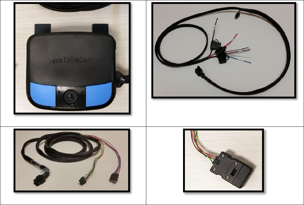
ER-SF1 unit
Vehicle Interconnect Cable with in-line fuses:
Red and Black wires = 5-amp fuses
Brown wire = 1-amp fuse
Standard Power Cable
J1939 CAN Coupler
If you are missing any materials, contact the Lytx U.S. Technical Support Center at 866.910.0403 or
email support@lytx.com to obtain the necessary materials before beginning installation.
Supplementing or substituting shipped materials could impair suitability and performance.
Required Tools
In addition to all guides and reference documents that you should read before beginning
installation, the following tools are required for installation:
Wire cutter
Wire crimper
Voltmeter
Vehicle panel removal tool
Flat-blade screwdriver
Cable ties
Phillips screwdriver
Electric Tape
Marking pen
T27 security Torx bit
T8 security Torx bit
Micro USB cable
Consult the vehicle’s maintenance, service, installation, and diagnostic guidelines provided by the
manufacturer of the vehicle for any additional tools needed.

ER-SF1 Event Recorder with J1939 Network Instructions for Self Installation
© 2017 Lytx, Inc. – Confidential & Proprietary – For Velociti’s Use Only Re Beta ER-SF1 Installations. Page 11 of 26
Optional Tools
The following tools are not required for installation but can be helpful:
Cordless driver
Add-a-circuits or vehicle specific
connectors
Grommets and looms
Flashlight
Paper towels/shop towel
Utility knife
Vehicle-specific panel clips
Spare 18-gauge wire
INSTALLATION PROCEDURES
Installation consists of three sections:
1. Mounting of the bracket and event recorder in the vehicle
2. Electrical connections and cable routing
3. Testing
Mount the Bracket and Event Recorder
CAUTION: To mount the bracket and ER, the air temperature must be at least 50F (10C).
WARNING: Before mounting the bracket and ER, consult the vehicle manufacturer’s
recommendations and any applicable federal, state, provincial and local laws that prohibit
mounting devices on vehicle’s windshield or other locations in a vehicle.
Mounting the bracket and ER consists of five main steps:
1. Review mounting location guidelines.
2. Clean and dry the windshield.
3. Mark the mounting location on the windshield.
4. Attach the bracket to the windshield.
5. Mount the ER to the bracket.
ER-SF1 Event Recorder with J1939 Network Instructions for Self Installation
© 2017 Lytx, Inc. – Confidential & Proprietary – For Velociti’s Use Only Re Beta ER-SF1 Installations. Page 12 of 26
Mounting Location Guidelines
CAUTION: An improperly positioned event recorder can reduce program effectiveness.
The event recorder needs to be mounted in a location that provides an unobstructed view of the
driver and the road in front of the vehicle.
1. Interior-facing Lens View: Must span from the outside shoulder of the driver to the
outside shoulder of a front seat passenger.
2. Exterior-facing Lens View
a. Must be inside the path of the wiper blades.
b. Must capture a clear view of everything in front of the vehicle, beginning as close to
the front of the vehicle as possible without cutting off the horizon.
To use the ER device to temporarily gauge the best position, first loosen the Torx screws so
the ER can rotate in the bracket. Then hold it up to the windshield.
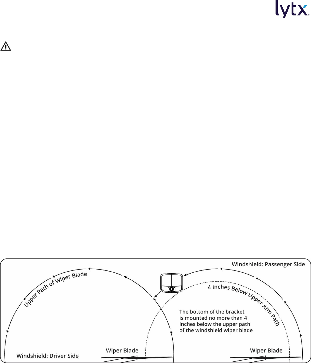
Mounting Location Restrictions and Exemption
The figures below provide Lytx’s recommendations for mounting the ER on the vehicle windshield
that work within the guidelines set forth by the Federal Motor Carrier Safety Administration
(FMCSA)*. However, some states have adopted laws that restrict locations where objects can be
attached to the vehicle windshield. Always refer to any applicable federal, state, provincial and
local laws that concern mounting devices on vehicle’s windshield or other locations in a vehicle
before choosing a mounting location.
ER-SF1 Event Recorder with J1939 Network Instructions for Self Installation
© 2017 Lytx, Inc. – Confidential & Proprietary – For Velociti’s Use Only Re Beta ER-SF1 Installations. Page 13 of 26
*FMCSA Allowance: Allows the event recorder to be mounted not more than 100 mm (four inches)
below the upper edge of the area swept by the windshield wipers or not more than 175 mm (7
inches) above the lower edge of the area swept by the windshield wipers, provided that the event
recorder is located outside the driver’s sight lines to the road and highway signs and signals. See
49 C.F.R. § 393.60(e).
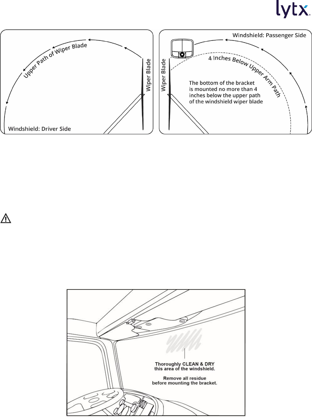
Clean and Dry the Windshield
CAUTION: These steps—especially use of the alcohol wipe—are critical to prevent the bracket
from falling off later.
1. Clean the mounting area on the windshield thoroughly with the alcohol wipe, removing any
debris and moisture. This should be the area behind the rear view mirror on the passenger
side or the equivalent area if there is no rear view mirror (see below).
2. Dry the mounting area thoroughly with a clean, dry cloth.
Thoroughly Clean and Dry the Glass
ER-SF1 Event Recorder with J1939 Network Instructions for Self Installation
© 2017 Lytx, Inc. – Confidential & Proprietary – For Velociti’s Use Only Re Beta ER-SF1 Installations. Page 14 of 26
Mark the Mounting Location on the Glass
CAUTION: Do not peel the backing from the adhesive strips on the bracket in this section.
1. Following the mounting location guidelines above, hold the assembly in place and trace the
outline of the bracket on the windshield with a marker. Make sure the traced guide marks are
level.
2. Remove the event recorder from the mounting bracket.
3. Check the fit of the bracket against the windshield. If the windshield is curved, you may
gently bend the bracket so it will lie flush against the glass.
4. Check again to make sure you’ve selected the best mounting location.
a. Sit in the driver’s seat while holding the ER device up. Make sure it doesn’t block the
driver’s view of the road.
b. Turn on the wipers and rotate mirrors, sun visors, and other objects near the ER to
make sure they cannot block either lens.
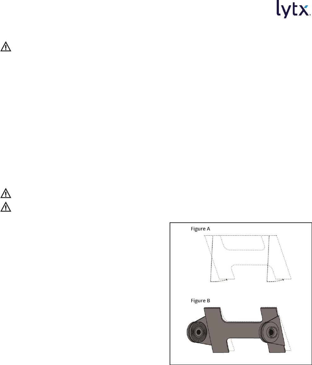
Attach the Bracket to the Windshield
CAUTION: The adhesive is very sticky. Once applied, it will not easily come off.
CAUTION: Do not apply excessive pressure as it may cause the windshield to break.
1. Remove the backing from the adhesive side
of the bracket.
2. Carefully attach the bracket to the
windshield.
a. Place the top edge of the bracket
against the windshield, aligned with
the marks, and make sure it is level.
b. Press the bracket firmly against the
windshield starting at the top and
pressing the sides downward. See
Figures A and B.
3. Check from outside the vehicle for large air
bubbles under the bracket. If you find any:
a. Apply additional pressure to the
bracket.
b. Use a small pin to create an escape path for the air.
ER-SF1 Event Recorder with J1939 Network Instructions for Self Installation
© 2017 Lytx, Inc. – Confidential & Proprietary – For Velociti’s Use Only Re Beta ER-SF1 Installations. Page 15 of 26
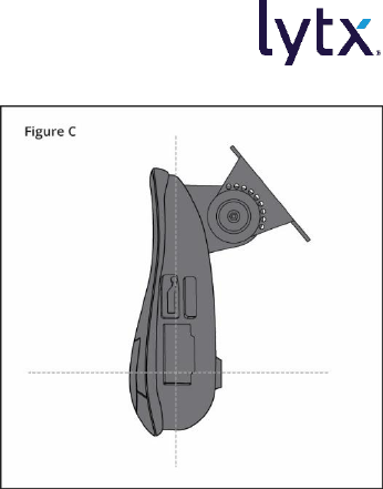
Mount the Event Recorder in the Bracket
1. Place the event recorder in the bracket.
2. Adjust the event recorder so it hangs vertically (plumb).
See Figure C.
3. Secure the event recorder in the bracket using the two
Torx screws.

ER-SF1 Event Recorder with J1939 Network Instructions for Self Installation
© 2017 Lytx, Inc. – Confidential & Proprietary – For Velociti’s Use Only Re Beta ER-SF1 Installations. Page 16 of 26
Connect Electrical Wiring
Connecting the electrical wiring consists of these main steps:
1. Review the electrical connection overview diagram and wiring suggestions.
2. Connect the three basic connections—the red, brown, and black wires on the Vehicle
Interconnect Cable.
3. Connect to the Vehicle J1939 Network Interface.
4. Route the ER cable.
Wiring Safety Warnings
WARNING: Only approved wire connection methods are recommended. Refer to the
vehicle manufacturer’s service manual to determine if Add-A-Circuit, Posi-Tap, sealing butt
connections, or OEM connections to open connection ports are approved. Never use plier tap
products such as scotch locks when installing the ER-SF1.
WARNING: Never wire the ER-SF1 in a manner that shares a connection with another
aftermarket product in the vehicle. Independent connections should always be used.
WARNING: All wires that carry electrical current must be fused. Failure to do so can lead
to serious personal injury and/or property damage. If any wires or cables containing fuses/fuse
boxes need to be cut or otherwise shortened, always be certain to replace such fuses/fuse boxes
or install new ones.
WARNING: Wire Protection: Take all necessary measures to protect all wire runs through a
metal surface with a grommet or other device and all wire runs outside the vehicle cab with a
loom. Always protect against wire fatigue and harness abrasion by properly attaching wires at
closely spaced intervals, while avoiding contact with sharp edges or doing anything else that
might result in exposed wires. All wires should be secured with tie wraps at least every two feet
or less. Do not overtighten any tie wraps.
Make certain that neither the cable nor your installation activities interferes with any
airbag-related mechanisms or otherwise risks affecting airbag deployment. Consult the
vehicle manufacturer for the location of any airbag sensors and systems and restrictions that may
apply.
ER-SF1 Event Recorder with J1939 Network Instructions for Self Installation
© 2017 Lytx, Inc. – Confidential & Proprietary – For Velociti’s Use Only Re Beta ER-SF1 Installations. Page 17 of 26
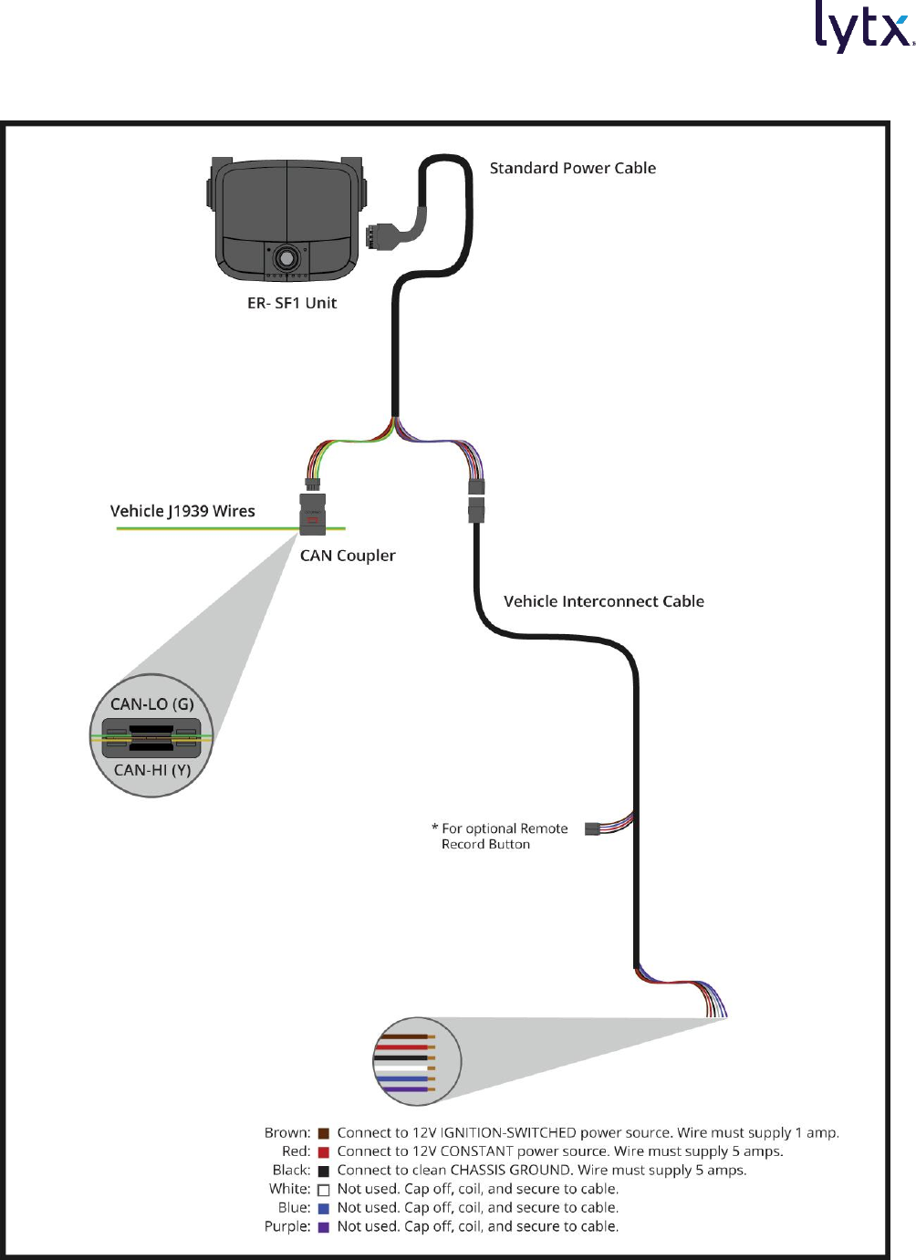
Electrical Connection Overview Diagram
ER-SF1 Event Recorder with J1939 Network Instructions for Self Installation
© 2017 Lytx, Inc. – Confidential & Proprietary – For Velociti’s Use Only Re Beta ER-SF1 Installations. Page 18 of 26
Wiring and Wire Termination Suggestions
WARNING: Failure to use proper wiring and wire terminations could lead to personal injury or
property damage. The following Wire Termination Suggestions should be followed to ensure
proper connections.
When installing the event recorder, there are several key rules to produce reliable electrical
connections:
1. Use ONLY 16- or 18-gauge automotive primary wire to connect to automotive circuits.
Specialty wire might be superior when used in its native environment, but not in the
automotive field (for example, Teflon wire is intended for high heat conditions, but should
never be used for connections of the event recorder in the vehicle).
2. For all connection methods, do not leave any exposed wire near the connector.
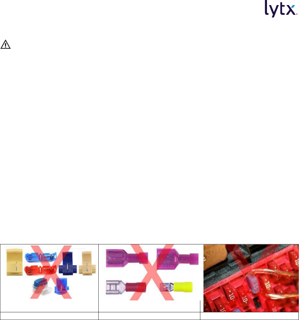
3. Do not use ScotchLoc, quick slide, or non-sealing butt connectors.
4. Posi-Tap connectors: Posi-Tap wiretap connectors may only be used inside the cab of the
vehicle and only for event recorder inputs. These include ignition, turn signals, and brake.
5. Crimp style connectors: All crimp style connectors must be the sealing type. Verify the
crimped connection is secure. Then heat up the connector to melt and seal it.
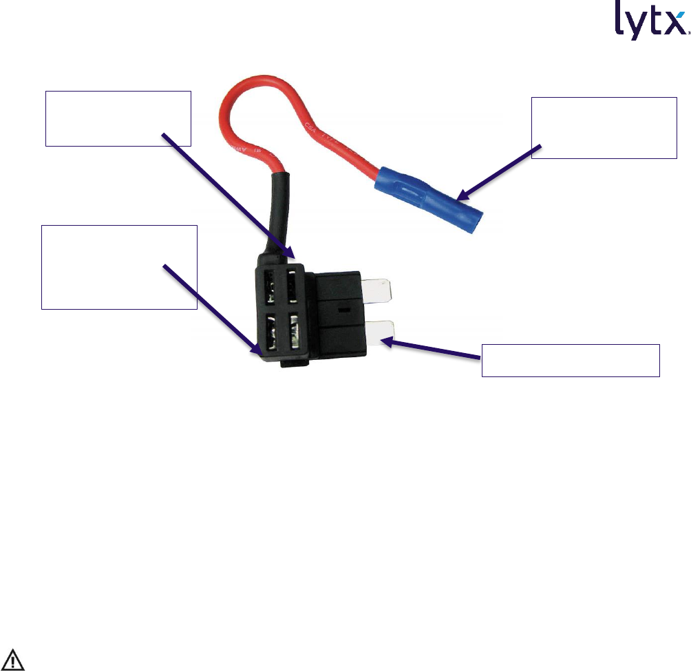
6. Fuse taps/Add-A-Circuits: If using a fuse tap (Add-A-Circuit), make sure that the hot leg of
the fuse receptacle connects to the leg of the fuse tap farthest from the connection wire. If
installed backwards, a fuse tap will compromise the original circuit. Never use a fuse tap on
an ECM, ECU, or control module circuit fuse.
ScotchLoc connectors
Quick Slide connectors
Do not tap wire as shown
ER-SF1 Event Recorder with J1939 Network Instructions for Self Installation
© 2017 Lytx, Inc. – Confidential & Proprietary – For Velociti’s Use Only Re Beta ER-SF1 Installations. Page 19 of 26
Basic Event Recorder Electrical Connections
A minimum of three connections are required for the event recorder to function. These leads are
found on the Vehicle Interconnect Cable terminating at the female end of the Molex connector.
The red and black leads have 5-amp inline fuses; the brown lead has a 1-amp inline fuse.
Required Connections
1. Red wire: Provides primary power and must be connected to a continuous power source.
2. Brown wire: Functions as an ignition-sense, used by the event recorder to perform
functions such as activating the IR Illuminator when the vehicle ignition is switched on.
3. Black wire: Functions as ground.
Connect the RED WIRE to a 12V-24V power source that is ALWAYS ON
CAUTION: THIS IS A FUSED CONNECTION. DO NOT CUT OFF OR REMOVE THE FUSE
HOLDER.
The event recorder always remains “on.” This requires a 12V or 24V power source that is not
controlled by the key nor any other device or switch. Typically, this connection is made just after
the fuse box on the battery-side of any vehicle control modules. Use a voltmeter to make sure the
circuit provides continuous 12V or 24V power when the key is removed from the ignition and all
lights, devices and switches are off.
Ensure Sufficient Current Draw: If you’re tapping into an existing vehicle wire, make sure it can
handle the additional current draw of the event recorder. A wire that reads 12V on a voltmeter
may not necessarily be able to supply enough current to the existing circuit and the event
Bottom fuse is
original circuit
fuse.
Top fuse is new
fuse for event
recorder.
Must be sealing
style connector.
“Hot” or powered leg.

ER-SF1 Event Recorder with J1939 Network Instructions for Self Installation
© 2017 Lytx, Inc. – Confidential & Proprietary – For Velociti’s Use Only Re Beta ER-SF1 Installations. Page 20 of 26
recorder. The gauge of wire being tapped into provides a good indication. A larger gauge wire is
often the best choice.
Connect the BROWN WIRE to a 12V-24V power source that is IGNITION-SWITCHED
CAUTION: THIS IS A FUSED CONNECTION. DO NOT CUT OFF OR REMOVE THE FUSE
HOLDER.
CAUTION: The brown wire to a 12V-24V power source that is ignition-switched is important to
ensure the event recorder can identify when the ignition is switched on and off and to control the
event recorder’s Hibernation mode. This connection requires a 12V or 24V power source that is
“on” either when the ignition is keyed all the way forward to the ON position and all the way back
to the OFF position. Failure to properly connect this fused connection may lead to vehicle battery
drain.
Common Mistake for Brown Wire Connections: This connection is often mistakenly made to a
modulated circuit—one that comes out of a computer control module running some subsystem in
the vehicle. This can give false ignition on/off signals. To avoid this, connect this wire to a circuit
that is on the battery side of any modules. Consult the vehicle wiring schematics or a local
authorized dealership to obtain this info.
Connect the BLACK WIRE to a Good Solid Vehicle Ground
CAUTION: THIS IS A FUSED CONNECTION. DO NOT CUT OFF OR REMOVE THE FUSE
HOLDER.
This connection is usually made via ring terminal to ground lug in the vehicle, supplied by the
vehicle manufacturer for aftermarket products. If one is not available, ensure that the connection
is solid to a metal portion of the vehicle which is directly grounded to the vehicle frame. Ensure
there is no corrosion or paint interfering with this connection.
Instructions for Basic Connections
1. Find a suitable location to make electrical connections (usually behind/under the
dashboard or power distribution center).
2. Connect the red, brown, and black wires from the Vehicle Interconnect Cable leads to the
vehicle as shown in the Electrical Connections Overview Diagram above. Be sure to follow
the parameters for each wire, detailed above.
Connect to the Vehicle J1939 Network Interface
Connectivity to the vehicle J1939 network is achieved with a coupling device called the CAN
Coupler. This device makes use of inductive technology to allow the ER to read the data on the
J1939 network without requiring any puncture, cut, or splice into the vehicle cabling.

ER-SF1 Event Recorder with J1939 Network Instructions for Self Installation
© 2017 Lytx, Inc. – Confidential & Proprietary – For Velociti’s Use Only Re Beta ER-SF1 Installations. Page 21 of 26
Refer to the Electrical Connection Overview Diagram above for the following steps.
1. Connect the CAN Coupler to the Standard Power Cable.
2. Find a suitable location along the vehicle J1939 network backbone to insert the CAN
Coupler. The CAN Coupler MUST be installed in the vehicle cab. It cannot be exposed to
moisture or inclement weather conditions.
3. Untwist approximately 2 inches of the vehicle’s J1939 wires, which are always a green and
yellow twisted pair.
4. Insert the vehicle’s J1939 wires into the CAN Coupler with the yellow wire on the CAN-HI (Y)
side and the green wire on the CAN-LO (G) side. Ensure that the wires are secured in the
tabs provided and properly oriented.
5. Place the cap on the CAN Coupler.
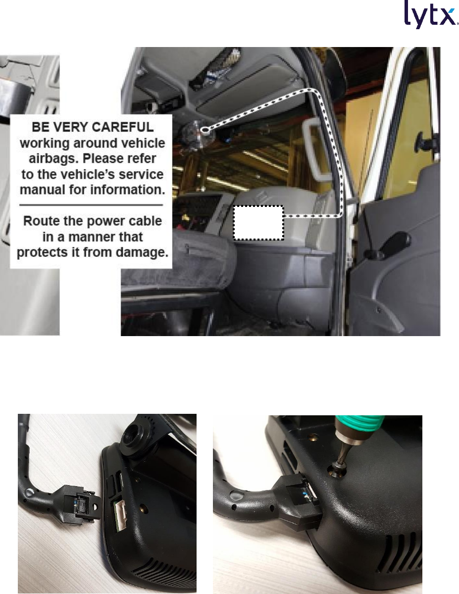
Route the ER Cable
Note: You may need to remove the window and door trim to route the cable underneath. These
typically snap on and off using special clips. In vehicles with side and curtain airbags, the clips are
often one-time use and may need to be replaced after removal. Please refer to the vehicle service
manual for information.
1. Route the end of the ER cable from the adapter to the nearest door pillar. Route the cable
behind and underneath the dash until reaching the kick panel.
2. Starting from below the dash near the kick panel, route the end of the ER cable up the door
pillar underneath the vertical door/window trim to the top of the door pillar.
3. Route the ER cable across the top of the windshield under the window trim or headliner to
the ER device (see below).
WARNING: WHEN INSTALLING THE CABLE IN A VEHICLE WITH SIDE OR CURTAIN
AIRBAGS, BE CERTAIN THAT NEITHER THE CABLE NOR YOUR INSTALLATION ACTIVITIES
INTERFERES WITH ANY AIRBAG-RELATED MECHANISMS OR OTHERWISE RISKS AFFECTING
AIRBAG DEPLOYMENT.
ER-SF1 Event Recorder with J1939 Network Instructions for Self Installation
© 2017 Lytx, Inc. – Confidential & Proprietary – For Velociti’s Use Only Re Beta ER-SF1 Installations. Page 22 of 26
Example Cable Routing in Vehicle
4. Connect the ER connector to the event recorder. Use the T8 security locking screw to lock
and secure the connector in place (see below).
ER-SF1 Locking Tab with T8 Security Screw
5. Make sure the cable is clear of any sharp edges, moving parts, and cannot get pinched in
the door jam.
Vehicle
Network
ER-SF1 Event Recorder with J1939 Network Instructions for Self Installation
© 2017 Lytx, Inc. – Confidential & Proprietary – For Velociti’s Use Only Re Beta ER-SF1 Installations. Page 23 of 26
6. Make sure the cable is tucked away and secured so that it cannot come loose. We
recommend using cable-ties every few inches along the route of the cable to secure it in
place.
Run Testing and Complete Installation
Boot Up the ER and Test Event Creation
1. Key the ignition to ON and plug the Vehicle Interconnect Cable to the Standard Power
Cable.
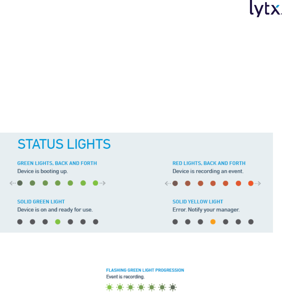
2. Observe the event recorder. The center LED status lights should turn green, then turn off.
The LED status lights then light up from left to right twice, indicating the device is booting
up. The center LED status light will then go to solid green.
3. Press either blue button on the unit to create a manual event. The LED status lights will
light up green one by one from left to right until all are lit (lasts ~10 seconds). Confirm this
light pattern.
Test Wire Connections and Settings in the Lytx Installation Tool
1. Connect a Windows laptop running the Lytx Installation Tool program to the ER-SF1 with
the USB cable.
a. Note: You may use a USB extension cable up to 3 feet in length.
2. Refer to the Lytx Installation Tool Guide for instructions on how to finalize the installation.
Ignition and the vehicle J1939 connection (via engine RPM) can be verified via the Lytx
Installation Tool.
Complete Installation
The ER-SF1 event recorder is installed and ready to use.

ER-SF1 Event Recorder with J1939 Network Instructions for Self Installation
© 2017 Lytx, Inc. – Confidential & Proprietary – For Velociti’s Use Only Re Beta ER-SF1 Installations. Page 24 of 26
1. Finalize all electrical connections. Use cable-ties to bundle and secure all wires.
2. Replace any trim pieces on the door pillar and dash that were removed.
3. Make sure the cable is routed safely and cannot get pinched in any moving parts.
4. Reaffirm you have taken the appropriate safety precautions while working around vehicle
airbags.
5. Keep the Torx wrench and this guide in a safe place for future use.
Final Checks
After installation of the ER-SF1 but prior to any operation of the vehicle, check all vehicle system
lights, signals, and any other devices (such as electronic log devices systems or CB radios) to make
sure they are working properly. Minimum checks should include the following (consult the vehicle
manufacturer’s service manual for additional checks that must occur):
1. Constant power: Ensure the ER is powered when the ignition is off (12V to red wire).
2. Switched power: Confirm 12V to the brown wire when the ignition is on.
3. Ground: Ensure the black wire is connected to a solid grounding point in the vehicle with
no paint or rust.
4. Event creation: Turn the vehicle on and press either blue button on the ER. Confirm an
event is created by verifying the LED’s light up green from left to right, one by one.
5. Check-in: Hold either blue button on the ER down for ~6 seconds. The center LED on the
unit should go out and come back on. Release the button and confirm that the unit has
attempted to contact Lytx, Inc. During the check-in process, the LEDs will blink and then
turn solid green progressively from left to right.
a. If an LED turns red, the check-in has failed and must be attempted again. There will
be some instances where check in is not possible due to cellular coverage and the
installation is still okay. After check in or failure, the center green LED will come on.
6. Start the vehicle, cycle the transmission, and confirm there are no error codes/check
engine lights.
7. Test the other vehicle components on the power circuit of the ER-SF1 to confirm their
functionality, especially if the circuit is shared.
8. Verify and diagnose all active faults in the vehicle system, other devices, and the ER-SF1
prior to completing the installation.
9. Place the driver safety card and the warning card included with the ER packaging on the
driver’s seat.
10. Place the decal indicating the vehicle is equipped with a recording device on the driver’s
seat. The customer is responsible for visibly displaying this decal.

ER-SF1 Event Recorder with J1939 Network Instructions for Self Installation
© 2017 Lytx, Inc. – Confidential & Proprietary – For Velociti’s Use Only Re Beta ER-SF1 Installations. Page 25 of 26
TROUBLESHOOTING & MAINTENANCE
Only a properly qualified technician should install and maintain the ER-SF1. Only a properly
qualified technician should install and maintain the ER-SF1. Any electrical work should be
performed only by an ASE (minimum T6 & L2), MECP or equivalent certified technician with an
expertise in installing and troubleshooting advanced vehicle onboard components including
multiplexed circuits. Lytx, Inc. disclaims all responsibility for any damages arising from improper
installation and maintenance of the ER-SF1.
Refer to the Lytx Maintenance Supplement for periodic maintenance requirements for the
ER-SF1.
Contact Technical Support
To obtain additional support and product information, contact the Lytx U.S. Technical Support
Center at 866.910.0403 or email support@lytx.com.
Troubleshooting Steps
Problem
Possible Causes and Solutions
The ER-SF1 is not booting
properly. The device briefly
connects to the Lytx Installation
Tool, then disconnects.
There may be insufficient current on the constant power connection.
Check that connection. Ensure the source wire is capable of supplying 5 amps.
There may be a loose or insufficient chassis ground. Inspect the ground
connection to ensure it's tight and it's in a location free of paint or rust.
The device does not connect to
the laptop at all.
There may be an issue with that specific USB port. Try connecting to a different
USB port on the laptop.
The laptop may not be detecting the device. Open Device Manager on your
laptop. Verify that "Remote NDIS6 based Device" shows up under "Network
Adapters".
The ER-SF1 may not be detecting Ignition from the brown wire. Check the wire for
damage. Check the wire with a voltmeter for 12V/24V with the ignition on. Check
the vehicle fuse for that circuit.
The Model and Device Serial
Number do not appear in the
Lytx Installation Tool.
There may be an issue with Windows Firewall. Plug the device in again and verify
that the Lytx Installation Tool is allowed through Windows Firewall.
The Lytx Connection is not being
detected in the Lytx Installation
Tool.
There may have been a momentary issue. Try creating a manual event and then
doing a forced check-in.
To manually create an event, push either of the blue manual record buttons on
the ER-SF1. The LED status lights on the ER-SF1 will light up green one-by-one
from the left to right until all are lit, indicating the event has been created.
After the event is created, hold one of the manual record buttons for 10 seconds
to attempt a forced check-in to Lytx. The LED status lights will light up and blink
one-by-one from the left to right until all are lit, indicating the check-in was
successful.
The device may be in an area without reception. Bypass this for now by checking
the "Known Issue Bypass" box. Re-test this connection when the device is in a
location with better reception.

ER-SF1 Event Recorder with J1939 Network Instructions for Self Installation
© 2017 Lytx, Inc. – Confidential & Proprietary – For Velociti’s Use Only Re Beta ER-SF1 Installations. Page 26 of 26
Problem
Possible Causes and Solutions
Engine RPM is not being
detected in the Lytx Installation
Tool.
Ensure the vehicle is running. Turn the device off and on either by disconnecting
the power cable or by entering the device's Diagnostic Mode.
The wires may be reversed over the CAN Coupler. Ensure that the Yellow wire is
on the CAN-HI (Y) side of the Coupler and the Green wire is on the CAN-LO (G)
side.
The connector may not be fully seated. Check the CAN Coupler to make sure it is
fully engaged.
The CAN Coupler may not have been placed on the CAN backbone, but on a stub.
Try moving the Coupler to a different location.
Ignition is not being detected in
the Lytx Installation Tool.
If the engine is already turned on, turn the engine off and then back on.
There may be an issue with the brown wire connection. Check the wire for
damage. Check the wire with a voltmeter for 12V/24V with the ignition on. Check
the vehicle fuse for that circuit.
The GPS time and coordinates
are not being detected OR only
zeroes are detected in the Lytx
Installation Tool.
The device may be in an area with poor reception. Try re-locating to a different
area and re-testing the signal.
The ER-SF1 fails to power up
after installation.
The vehicle battery may be disconnected. Reconnect the battery or check the
battery cut-off switch.
Ensure the red wire on the vehicle interconnect cable is connected to a constant
power source.
The fuse may be missing or open. Check the fuse panel location for constant
power. Ensure the proper value fuse is installed and not open.
The connection between the standard power cable and the vehicle interconnect
cable may not be fully secured. Check the connection. Disconnect and reconnect
the cables, ensuring the connection “snaps”.
The red wire on the vehicle interconnect cable may be damaged. Check the entire
length of the wire for damage/cuts. Fix any issues.
The ER-SF1 does not come out
of Hibernate mode when the
ignition is activated.
There may be an issue with the brown wire connection. Check the wire for
damage. Check the wire with a voltmeter for 12V/24V with the ignition on. Check
the vehicle fuse for that circuit.
The ER-SF1 boots up and
displays a solid Yellow LED
status light.
There is an issue with the cellular modem. In the case of a CDMA unit, it indicates
that the cellular modem has not been provisioned properly. In the case of a GSM
modem, it could be that the SIM card is not seated properly. Reseat and see if the
light changes to Green. If the status light stays Yellow, contact Lytx Technical
Support.