M Labs Technologies PH01 GPS Tracker User Manual Manual
M-Labs Technologies, LLC GPS Tracker Manual
UserManual.wiki
>
M Labs Technologies
>
PH01 User Manual
Manual
Navigation menu
Upload a User Manual
Namespaces
Wiki Guide
HTML
PDF
Info
Views
User Manual
Discussion / Help
Navigation
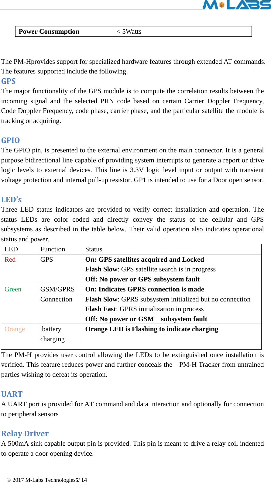
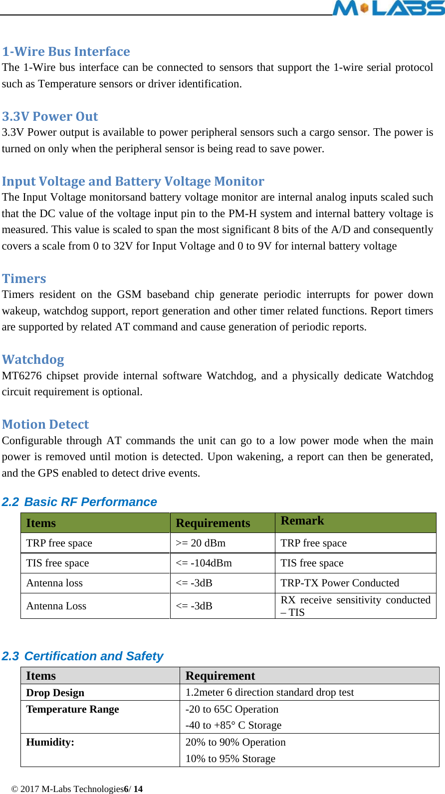
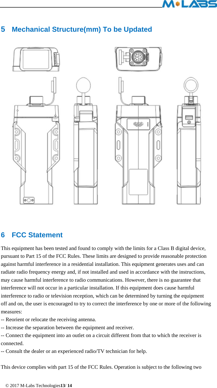
![© 2017 M-Labs Technologies4/ 14 The device will use one dual band antenna(GSM900&PCS1800)and one dedicate GPS antenna. 2 Hardware Design 2.1 Basic Hardware Items Requirement Baseband Chipset MT6276A RF 2G Transceiver RF3235 RF 3G Transceiver RF7411TR7 Memory MCP_NAND 1Gb(x16) / mobile DDR 512Mb(x16) Air Interface Supportfor WCDMA Class 12 GPRS, GPS Frequency 2G band support :GSM850 and PCS1900 Support for 12 class GPRS 3G band support : Band2 and Band5 Antenna Internal Antenna[850M&1900M] GPS Antenna Dedicate high performance ceramic antenna UIM requirement No-UIM mode, GSM card connector optional Interface UART TX UART RX 12V DC Input(1.2A max current) Main/Aux/Solar inputs Relay Drive (Open Drain ,500mA current) GPIO1 1-Wire Bus Interface 3.3V Power out Voltage/Battery Monitor internal analog input scaled Build in battery manager Supported Dedicate Timers No Watchdog Supported Motion Detect GPS/Accelerometer LED 3 LED’s (Red, Green, Orange) Battery Built in battery(4400mAh Lion) Working Time >40 hours (Continuously On) > 250 days Standby Power switch No Power Cable color 12 colors Power Cable connector type 12pin](https://usermanual.wiki/M-Labs-Technologies/PH01/User-Guide-3728420-Page-4.png)