M Labs Technologies PH01 GPS Tracker User Manual Manual
M-Labs Technologies, LLC GPS Tracker Manual
Manual

© 2017 M-Labs Technologies1/ 14
User Manual
For the
PM-H
Vehicle Tracking Device
November28, 2017
R1.0
Author Revision Changes Date
1.0
Initial version
2017-11-28
The information presented in this document is strictly confidential and contains trade secrets
and other confidential information that are the exclusive property of M-Labs Technologies

© 2017 M-Labs Technologies2/ 14
Contents
1 Introduction ............................................................................................................................... 3
2 Hardware Design....................................................................................................................... 4
2.1 Basic Hardware ................................................................................................................. 4
2.2 Basic RF Performance....................................................................................................... 6
2.3 Certification and Safety..................................................................................................... 6
3 Software Features ...................................................................................................................... 8
3.1 Basic Software .................................................................................................................. 8
3.2 Remote Update .................................................................................................................. 8
3.3 Auto Execute ..................................................................................................................... 8
3.4 Power Modes ..................................................................................................................... 8
3.5 Report ................................................................................................................................ 9
Report Queuing ......................................................................................................................... 9
Ack’ed Mode ............................................................................................................................ 9
Event Report Format ............................................................................................................... 10
3.6 Reset ................................................................................................................................ 10
Context Preservation ............................................................................................................... 10
3.7 Startup Banner ................................................................................................................. 10
4 Test Method ............................................................................................................................. 11
4.1 Hardware ......................................................................................................................... 11
4.2 Software Test ................................................................................................................... 11
5 Mechanical Structure(mm) To be Updated ............................................................................. 13
6 FCC Statement ........................................................................................................................ 13
7 IC STATEMENT ..................................................................................................................... 14
© 2017 M-Labs Technologies3/ 14
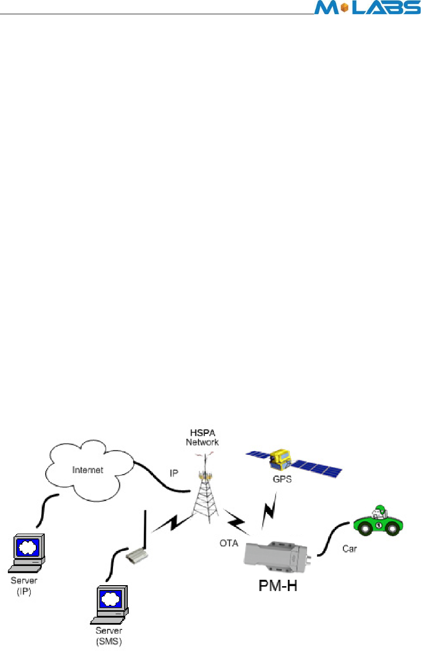
1 Introduction
ThePM-His a self-Contained vehicle tracking device that combines GPS location with
GSM/GPRS/WCDMA connectivity.
ThePM-H appears to a user or a server application as a single endpoint device. It can be
queried, updated and configured either through a serial connection, or an over the air GPRS or
WCDMA IP connection, or through SMS messaging. ThePM-Hpresents itself over these
connections as an enhanced cellular modem with attached functional elements. These
elements include:
GPS location engine
1 General Purpose Bidirectional I/O (GPIO) pin
1 Relay drive pin output
1 1-Wire Bus Interface
3.3V Power out for Peripheral Sensors
Serial UART port
Input voltagesand Battery Voltage monitor
Timers
Watchdog lockup protection
Motion detection
Access to these elements and general-purpose interfaces is done through an extended AT
command set as defined herein.
Application scene:
This product will be designed based on the 2G or WCDMAwirelessdata/MT6276
Baseband chipset, which includes GPS functionality, ARM CPU and GPRS protocol.
This baseband internal connection 8M serial flash, GSM 900M/1800M/GPS RF
Transceiver, and RF Front end circuit.

© 2017 M-Labs Technologies4/ 14
The device will use one dual band antenna(GSM900&PCS1800)and one dedicate GPS
antenna.
2 Hardware Design
2.1 Basic Hardware
Items
Requirement
Baseband Chipset
MT6276A
RF 2G Transceiver
RF3235
RF 3G Transceiver
RF7411TR7
Memory
MCP_NAND 1Gb(x16) / mobile DDR
512Mb(x16)
Air Interface
Supportfor WCDMA Class 12 GPRS, GPS
Frequency 2G band support :GSM850 and PCS1900
Support for 12 class GPRS
3G band support : Band2 and Band5
Antenna
Internal Antenna[850M&1900M]
GPS Antenna
Dedicate high performance ceramic antenna
UIM requirement No-UIM mode, GSM card connector optional
Interface UART TX
UART RX
12V DC Input(1.2A max current)
Main/Aux/Solar inputs
Relay Drive (Open Drain ,500mA current)
GPIO1
1-Wire Bus Interface
3.3V Power out
Voltage/Battery Monitor internal analog input scaled
Build in battery manager Supported
Dedicate Timers No
Watchdog Supported
Motion Detect
GPS/Accelerometer
LED
3 LED’s (Red, Green, Orange)
Battery
Built in battery(4400mAh Lion)
Working Time >40 hours (Continuously On)
> 250 days Standby
Power switch No
Power Cable color 12 colors
Power Cable connector type 12pin

© 2017 M-Labs Technologies5/ 14
Power Consumption < 5Watts
The PM-Hprovides support for specialized hardware features through extended AT commands.
The features supported include the following.
GPS
The major functionality of the GPS module is to compute the correlation results between the
incoming signal and the selected PRN code based on certain Carrier Doppler Frequency,
Code Doppler Frequency, code phase, carrier phase, and the particular satellite the module is
tracking or acquiring.
GPIO
The GPIO pin, is presented to the external environment on the main connector. It is a general
purpose bidirectional line capable of providing system interrupts to generate a report or drive
logic levels to external devices. This line is 3.3V logic level input or output with transient
voltage protection and internal pull-up resistor. GP1 is intended to use for a Door open sensor.
LED’s
Three LED status indicators are provided to verify correct installation and operation. The
status LEDs are color coded and directly convey the status of the cellular and GPS
subsystems as described in the table below. Their valid operation also indicates operational
status and power.
LED Function Status
Red GPS On: GPS satellites acquired and Locked
Flash Slow: GPS satellite search is in progress
Off: No power or GPS subsystem fault
Green
GSM/GPRS
Connection
On: Indicates GPRS connection is made
Flash Slow: GPRS subsystem initialized but no connection
Flash Fast: GPRS initialization in process
Off: No power or GSM subsystem fault
Orange
battery
charging
Orange LED is Flashing to indicate charging
The PM-H provides user control allowing the LEDs to be extinguished once installation is
verified. This feature reduces power and further conceals the PM-H Tracker from untrained
parties wishing to defeat its operation.
UART
A UART port is provided for AT command and data interaction and optionally for connection
to peripheral sensors
Relay Driver
A 500mA sink capable output pin is provided. This pin is meant to drive a relay coil indented
to operate a door opening device.

© 2017 M-Labs Technologies6/ 14
1-Wire Bus Interface
The 1-Wire bus interface can be connected to sensors that support the 1-wire serial protocol
such as Temperature sensors or driver identification.
3.3V Power Out
3.3V Power output is available to power peripheral sensors such a cargo sensor. The power is
turned on only when the peripheral sensor is being read to save power.
Input Voltage and Battery Voltage Monitor
The Input Voltage monitorsand battery voltage monitor are internal analog inputs scaled such
that the DC value of the voltage input pin to the PM-H system and internal battery voltage is
measured. This value is scaled to span the most significant 8 bits of the A/D and consequently
covers a scale from 0 to 32V for Input Voltage and 0 to 9V for internal battery voltage
Timers
Timers resident on the GSM baseband chip generate periodic interrupts for power down
wakeup, watchdog support, report generation and other timer related functions. Report timers
are supported by related AT command and cause generation of periodic reports.
Watchdog
MT6276 chipset provide internal software Watchdog, and a physically dedicate Watchdog
circuit requirement is optional.
Motion Detect
Configurable through AT commands the unit can go to a low power mode when the main
power is removed until motion is detected. Upon wakening, a report can then be generated,
and the GPS enabled to detect drive events.
2.2 Basic RF Performance
Items Requirements
Remark
TRP free space >= 20 dBm TRP free space
TIS free space <= -104dBm TIS free space
Antenna loss <= -3dB TRP-TX Power Conducted
Antenna Loss <= -3dB
RX receive sensitivity conducted
– TIS
2.3 Certification and Safety
Items
Requirement
Drop Design 1.2meter 6 direction standard drop test
Temperature Range -20 to 65C Operation
-40 to +85° C Storage
Humidity: 20% to 90% Operation
10% to 95% Storage

© 2017 M-Labs Technologies7/ 14
Altitude: -500 to +18,000m
Vehicle ISO Test ISO7637-2-2004; ISO7637-3-2007; ISO10605-2008;
ISO16750-2-2010
FCC Certification
FCC 47 CFR Part 15 ,Part2,Part 22,Part 24
Others Operator Requirement Industry Canada/ AT&T (optional)
ESD Requirement 10KV non-Conductive

© 2017 M-Labs Technologies8/ 14
3 Software Features
3.1 Basic Software
Items
Requirement
Air Interface GSM850, PCS1900, WCDMA Band II, WCDMA Band V,
GPS
GPRS Data Supported
IP Stack
Ipv4/IPV6
Upgrade Method
Remote update/ PC tool
Remote Update
Supported
Power Modes
Supported
AT Command
Supported
Report
Supported;3000records
Driver
GPIO,LED,GPS,UART,3.3V out
GPIO Interrupt for Door Open Detect
LEDs
GPS Status, WCDMA Status
Watch Dog
Supported
Reset
Soft reset
Startup Banner
Supported
3.2 Remote Update
The PM-Hsupports OTA field upgrades of the PM-Hresident application. An over the air
TFTP (Trivial File Transfer Protocol) connection is made over a UDP/IP connection. A
replacement file is then transferred from a server to the PM-Hand that file replaces the
previous application image.
3.3 Auto Execute
The Auto Execute Utility copies the contents of file system.exf into system executable RAM
and executes it from there. This file is the factory default application. Another file named
custom.exf can be loaded into the file system.
Auto Execute will look first for a file named update.exf and load and execute that in place of
custom.exf if it exists. If update.exf executes successfully, the previous copy of custom.exf is
deleted from the file system and update.exf is renamed to custom.exf.
3.4 Power Modes
The PM-H device supports several power modes that are set by the power mode command. In
full power mode the GPS is active and the cellular subsystem will maintain a persistent
cellular connection whenever service is available. IP connection is maintained according to
© 2017 M-Labs Technologies9/ 14
the configuration of the device.
The device can be put into several levels of low power mode whenever it runs on the internal
backup battery, or if the external input voltage is low or if it is not movingdepending on how
the unit is configured through AT commands.
Power Mode
Cellular
GPS
Full Power (Track)
On
On
Listen
On
Off
Stealth Off Off
The device would return to full power whenever an event occurs that triggers a report. Those
events include:
Report timer
GPIO change
IP change
Battery threshold
Heartbeat
Watchdog
Power-up
Motion Detected
Any hardware or software reset will return the device to full power mode.
3.5 Report
The PM-H captures data and forms a report record with that data. A report is a data structure
containing all of the sensory and other typically useful data on the device. Reports are
generated in response to specified events, such as periodic timeout, speed threshold,
geo-fence crossing, etc., or in response to a Report Now command (AT+XRN).
Report Queuing
If a report trigger occurs while UDP connection is unavailable, it will be queued until
connection becomes available and transmitted at such time. The only way report(s) can be lost
is if too many reports are queued and the report-queue is overflowing. In such case the earliest
report(s) will be discarded. The size of the queue can be configured via the Report Queue
(AT+XRPQ) command.
Ack’ed Mode
UDP is not a 100% reliable connection and occasional reports or command/responses may be
lost. Since all commands have responses, the server can repeat any command to which there
is no response. In order to assure reliable reception of reports, Arsenal devices can be
configured either in Normal or Ack’ed mode to send the reports. In the Normal mode the
reports are simply sent “as is” with no acknowledgment from the server. In the Ack’ed mode
every report sent is expected to be acknowledged by the server by sending back an ACK
message back. If acknowledgement is not received within the specified timeout, the report is

© 2017 M-Labs Technologies10/ 14
re-sent. If the report is not acknowledged after the specified number of attempts, it is queued.
If acknowledgement is received after the report is queued (i.e. past timeout of the last attempt),
it is ignored.
Report is not considered “complete” until its acknowledgement is received. Thus, if report X
is sent and report X+1 is triggered while waiting for acknowledgement of X, report X+1 will
be queued until such acknowledgement is received and only then sent. The Arrow will
attempt to re-send queued report(s) every time a new report is triggered. If there is more than
one report queued, the reports will attempt to be sent in the order of triggering and only once
the report is acknowledged, the next report is attempted. This assures that reports are sent and
received in order.
Ack’ed mode assures that all reports are received, but adds overhead in time and data. Report
that is not acknowledged is sent again and eventually will be queued and sent again. The
number and frequency of re-tries is configurable via the Report Acknowledgement command
(AT+XRPA).
Event Report Format
Reports can be generated in either an ASCII representation of hex or as actual binary encoded
hex. The reporting format is selected via Report Format (AT+XRPF) command. Note that
whilethe logical content of the report is the same in both representations, the size for an
ASCII report is twice the size of actual numbers of bytes compared to binary representation.
3.6 Reset
There are a number of resets available on the device. Soft reset resets the baseband only by
using an internal watchdog, while hard reset power cycles the whole device. There is also an
option to reset the GPS sub-system only.
Context Preservation
When a reset is caused by the Network Watchdog or by the Reset command (modes 0,1), the
context of the system is being preserved and is restored after the reset. The context includes
all the periodic timers, the report queue, the odometer, etc. This allows to reset the unit as a
troubleshooting measure either periodically or due to Network Watchdog without losing
reports that are already in the queue or are pending on running timers. Note that the reset
process may cause 1-2min of inaccuracy in the timers and should not be considered as very
precise.
3.7 Startup Banner
After a reset a startup banner is printed through the UART only. The format and content of
the banner shown below:
PROD: PUMA-H
IMEI: 353782066499613
IMSI: 310410964436268
ICCID: 89014103279644362684

© 2017 M-Labs Technologies11/ 14
MDL: 3005R04
BIN: 2.0.6
APP: 3.2.4
IO: 1.1.2
CFG: 0025 Puma/Jaguar-HSPA-KORE
IP: "34.224.196.58",15030
LPORT: 17006
APN: C2.KOREM2M.COM
SIM: Detected
Ready
4 Test Method
4.1 Hardware
Test Item Description
Baseband Function Test
• Power Input Test
• Power Consumption and Current Test
• Heat Dissipation Test
• UART Stability Test
• GPIO Level Test
• LED Stability Test
• Drop Down Test
• ESD Test
• High/Low Temperature Test
• Humidity Test
RF Test • RF Performance Test
• GPS Performance Test
• Antenna Performance Test
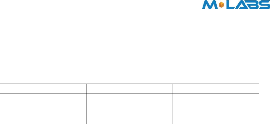
4.2 Software Test
Test Environment Construct
Message Test environment
1. USB dongle and PC as message server
2. Send message to PM-H
UDP Test environment
1. Connect dongle to PC and create dialup as ip server
2. PM-H create IP connection to server
UART Test environment
1. Connect PM-H to pc with com serial cable
2. Open Terminal tool and send at command
3. Response can be shown at terminal window
© 2017 M-Labs Technologies12/ 14
© 2017 M-Labs Technologies13/ 14
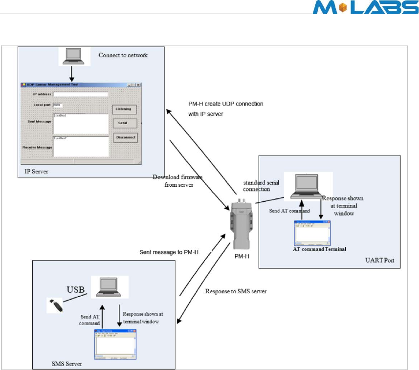
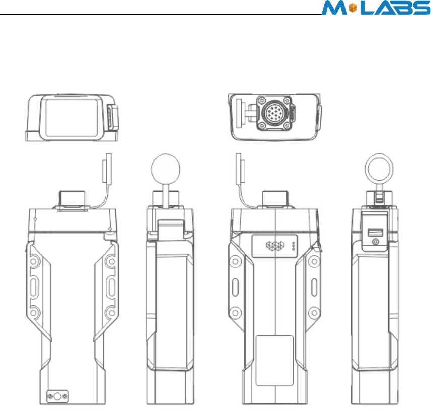
5 Mechanical Structure(mm) To be Updated
6 FCC Statement
This equipment has been tested and found to comply with the limits for a Class B digital device,
pursuant to Part 15 of the FCC Rules. These limits are designed to provide reasonable protection
against harmful interference in a residential installation. This equipment generates uses and can
radiate radio frequency energy and, if not installed and used in accordance with the instructions,
may cause harmful interference to radio communications. However, there is no guarantee that
interference will not occur in a particular installation. If this equipment does cause harmful
interference to radio or television reception, which can be determined by turning the equipment
off and on, the user is encouraged to try to correct the interference by one or more of the following
measures:
-- Reorient or relocate the receiving antenna.
-- Increase the separation between the equipment and receiver.
-- Connect the equipment into an outlet on a circuit different from that to which the receiver is
connected.
-- Consult the dealer or an experienced radio/TV technician for help.
This device complies with part 15 of the FCC Rules. Operation is subject to the following two

© 2017 M-Labs Technologies14/ 14
conditions:
(1) This device may not cause harmful interference, and (2) this device must accept any
interference received, including interference that may cause undesired operation.
Changes or modifications not expressly approved by the party responsible for compliance could
void the user's authority to operate the equipment.
RF Exposure Warning Statements:
The antenna(s) used for this transmitter must be installed to provide a separation distance of at
least 20 cm from all persons during the normal operations.
7 IC STATEMENT
This device complies with Industry Canada licence-exempt RSS standard(s). Operation is subject
to the following two conditions: (1) this device may not cause interference, and (2) this device
must accept any interference, including interference that may cause undesired operation of the
device.
Le présentappareilestconforme aux CNR d'Industrie Canada applicables aux appareils radio
exempts de licence. L'exploitationestautorisée aux deux conditions suivantes : (1) l'appareil ne doit
pas produire de brouillage, et (2) l'utilisateur de l'appareildoit accepter tout
brouillageradioélectriquesubi, mêmesi le brouillageest susceptible d'encompromettre le
fonctionnement.
In order to avoid the possibility of exceeding the IC radio frequency exposure limits, human
proximity to the antenna shall not be less than 20cm (8 inches) during normal operation.
Afind'éviter la possibilité de dépasser les limitesd'exposition aux fréquences radio de la IC
CNR102, la proximitéhumaine à l'antenne ne doit pas êtreinférieure à 20 cm (8 pouces) pendant
le fonctionnement normal.