M Labs Technologies TV01 GPS Tracker User Manual
Montage Systems, Inc. GPS Tracker
UserManual.wiki
>
M Labs Technologies
>
TV01 User Manual
User manual
Navigation menu
Upload a User Manual
Namespaces
Wiki Guide
HTML
PDF
Info
Views
User Manual
Discussion / Help
Navigation
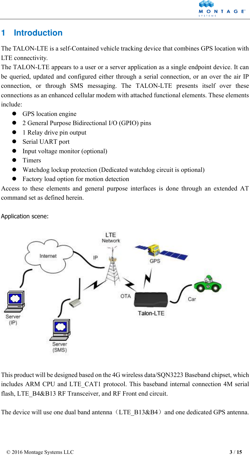
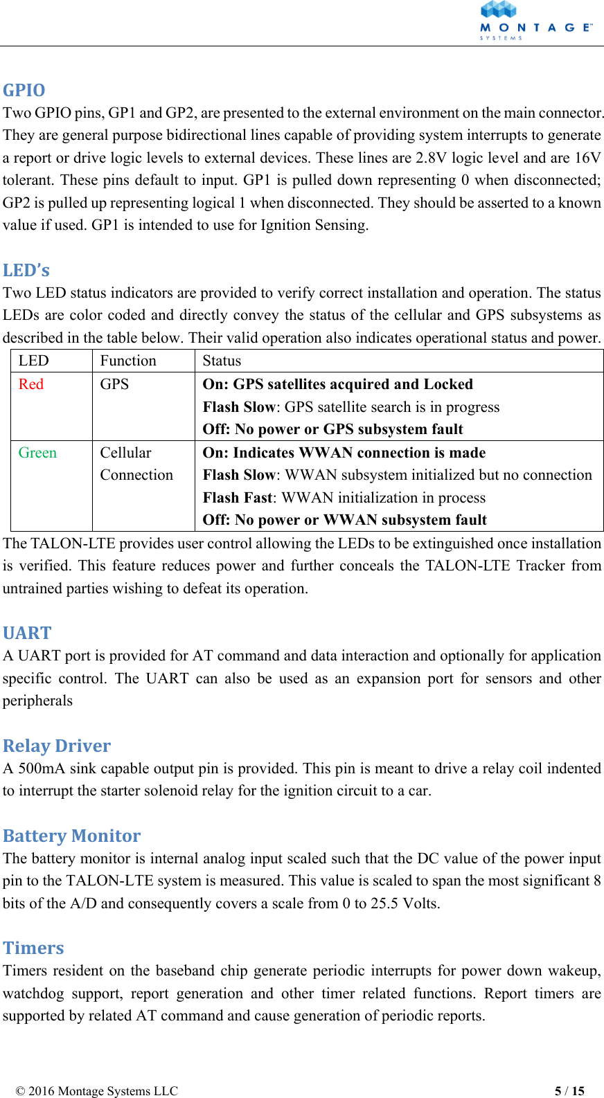
![© 2016 Montage Systems LLC 4 / 15 2 Hardware Design 2.1 Basic Hardware Items Requirement Baseband Chipset SQN3223 RF 4G Transceiver SQN3241 Air Interface Support for LTE_B13, LTE_B4 Frequency B4(MHZ): TX(1710-1755) RX(2110-2155) B13(MHZ): TX(777-787) RX(746-756) Antenna Internal Dual Antennas(Main & Diversity) [B4&B13] GPS Antenna Dedicate high performance ceramic antenna UIM requirement Support: 2FF SIM Interrupt Mode No Support:Hot Plug/Unplug Interface UART TX UART RX USB Battery Monitor UART RX Build in battery manager 12V DC Input(1A current) Relay Drive (12V Output ,500mA current) GPIO1 GPIO2 internal analog input scaled (Optional) Supported Dedicate Timers No Watchdog Supported Motion Detect Supported(GPS/G-Sensor) LED 2 LED Supported 2 LED’s (one is RED,one is Green) Battery Build in battery(80MAH Lion) Working Time 4 hours Power switch Yes(built in power switch) Power Cable color 10 colors Power Cable connector type 10pin connector Power Consumption < 5Watts The TALON-LTE provides support for specialized hardware features through extended AT commands. The features supported include the following. GPS The major functionality of the GPS module is to compute the correlation results between the incoming signal and the selected PRN code based on certain Carrier Doppler Frequency, Code Doppler Frequency, code phase, carrier phase, and the particular satellite the module is tracking or acquiring.](https://usermanual.wiki/M-Labs-Technologies/TV01/User-Guide-3164183-Page-4.png)