M2Communication 8001UX36LDRZ24 Sigfox Verified Uplynx RCZ24 Module User Manual rev
M2Communication Inc. Sigfox Verified Uplynx RCZ24 Module rev
User Manual rev.pdf
RM-UPLYNX-E003 version 1.0
Confidential and Proprietary
1
Uplynx-M-RCZ24
Module
Users Manual
M2COMMUNICATION Inc.

RM-UPLYNX-E003 version 1.0
Confidential and Proprietary
2
COPYRIGHT AND DISCLAIMER
Copyright © 2017 M2COMMUNICATION Inc.
All rights reserved. This document is the property of M2COMMUNICATION Inc. It contains
information which is confidential and proprietary to M2COMMUNICATION Inc. No part of this
document may be copied, reproduced or disclosed to third parties without the prior written
consent of M2COMMUNICATION Inc.
Disclaimer
This document contains confidential information and is subject to the terms and conditions set
forth in the Non-Disclosure Agreement between the Recipient Entity and M2Communication,
Inc. (“M2COMM”) The information in this document is believed to be accurate in all respects at
the time of publication but is subject to change without notice. M2COMM assumes no
responsibility for errors and omissions, and disclaims responsibility for any consequences
resulting from the use of information included herein. Additionally, M2COMM assumes no
responsibility for the functioning of un-described features or parameters. M2COMM reserves
the right to make changes without further notice. M2COMM makes no warranty,
representation or guarantee regarding the suitability of its products for any particular purpose,
nor does M2COMM assume any liability arising out of the application or use of any product or
circuit, and specifically disclaims any and all liability, including without limitation consequential
or incidental damages. M2COMM products are not designed, intended, or authorized for use in
applications intended to support or sustain life, or for any other application in which the failure
of the M2COMM product could create a situation where personal injury or death may occur.
Should Buyer purchase or use M2COMM products for any such unintended or unauthorized
application, Buyer shall indemnify and hold M2COMM harmless against all claims and damages.
Trademarks
M2COMM and the M2COMM logo are trademarks or registered trademarks of
M2COMMUNICATION INC. All other company or product names mentioned herein are
trademarks or registered trademarks of their respective companies.
Contact Information
M2COMMUNICATION Inc.
15F-1, No.32, Gaotie 2nd Road,
Zhubei City,
Hsinchu County 302,
Taiwan, R.O.C.

RM-UPLYNX-E003 version 1.0
Confidential and Proprietary
3
Revision Control
Rev
Date
Description of Change
Approved
1.0
04/20/2017
Released
Charles Lee

RM-UPLYNX-E003 version 1.0
Confidential and Proprietary
4
Federal Communication Commission Interference Statement
This device complies with Part 15 of the FCC Rules. Operation is subject to the following two
conditions: (1) This device may not cause harmful interference, and (2) this device must accept
any interference received, including interference that may cause undesired operation.
This equipment has been tested and found to comply with the limits for a Class B digital device,
pursuant to Part 15 of the FCC Rules. These limits are designed to provide reasonable
protection against harmful interference in a residential installation. This equipment generates,
uses and can radiate radio frequency energy and, if not installed and used in accordance with
the instructions, may cause harmful interference to radio communications. However, there is
no guarantee that interference will not occur in a particular installation. If this equipment does
cause harmful interference to radio or television reception, which can be determined by
turning the equipment off and on, the user is encouraged to try to correct the interference by
one of the following measures:
Reorient or relocate the receiving antenna.
Increase the separation between the equipment and receiver.
Connect the equipment into an outlet on a circuit different from that to which the
receiver is connected.
Consult the dealer or an experienced radio/TV technician for help.
FCC Caution: Any changes or modifications not expressly approved by the party responsible for
compliance could void the user's authority to operate this equipment.
This transmitter must not be co-located or operating in conjunction with any other antenna or
transmitter.
Radiation Exposure Statement:
This equipment complies with FCC radiation exposure limits set forth for an uncontrolled
environment. This equipment should be installed and operated with minimum distance 20cm
between the radiator & your body.

RM-UPLYNX-E003 version 1.0
Confidential and Proprietary
5
This device is intended only for OEM integrators under the following conditions:
I. The antenna must be installed such that 20 cm is maintained between the antenna and
users, and
II. The transmitter module may not be co-located with any other transmitter or antenna.
As long as 2 conditions above are met, further transmitter tests will not be required. However,
the OEM integrator is still responsible for testing their end-product for any additional
compliance requirements required with this module installed
IMPORTANT NOTE: In the event that these conditions cannot be met (for example certain
laptop configurations or co-location with another transmitter), then the FCC authorization is no
longer considered valid and the FCC ID cannot be used on the final product. In these
circumstances, the OEM integrator will be responsible for re-evaluating the end product
(including the transmitter) and obtaining a separate FCC authorization.
End Product Labeling
This transmitter module is authorized only for use in devices where the antenna may be
installed such that 20 cm is maintained between the antenna and users. The final end product
must be labeled in a visible area with the following:
“Contains FCC ID: 2AFXU8001UX36LDRZ24”
The grantee's FCC ID can be used only when all FCC compliance requirements are met.
Manual Information to the End User
The OEM integrator has to be aware not to provide information to the end user regarding how
to install or remove this RF module in the user’s manual of the end product which integrates
this module.
The end user manual shall include all required regulatory information/warning as show in this
manual.

RM-UPLYNX-E003 version 1.0
Confidential and Proprietary
6
Table of Contents
1 Product Overview ................................................................................. 9
2 Product Features ................................................................................. 9
3 Functional Description .........................................................................10
4 Pin Assignment and Package Mechanicals .........................................11
5 Electrical Specifications ......................................................................13
6 Preloaded Software ............................................................................16
6.1 Sigfox Verified AT command ........................................................................................ 16
6.2 Special Notes for Sigfox AT command interface ........................................................... 18
6.3 Bootloader ..................................................................................................................... 18
6.4 Device ID, KEY and Portable access code ...................................................................... 19
7 Transmission Power and Current Consumption ..................................19
7.1 Transmission Power vs. Input Voltage .......................................................................... 19
7.2 Current Profile and Measurement ................................................................................. 20
8 Application Information ........................................................................21
8.1 Mounting Considerations .............................................................................................. 21
8.2 Recommended connection to essential pins ................................................................. 21
8.3 Switch ON and OFF procedure ...................................................................................... 22
8.4 RF power and current measurement. ............................................................................ 22
8.5 RF Grounding for FCC compliance ................................................................................. 22
8.6 Recommended Antenna ................................................................................................ 23
9 Certification .........................................................................................23
10 Order Information ................................................................................23

RM-UPLYNX-E003 version 1.0
Confidential and Proprietary
7
List of Figures
Figure 4-1 Bottom view of module ......................................................................................... 11
Figure 4-2 Module Pinout........................................................................................................ 12
Figure 7-1 Current Profile ........................................................................................................ 20
Figure 8-1 Typical Application Circuit ...................................................................................... 22

RM-UPLYNX-E003 version 1.0
Confidential and Proprietary
8
List of Tables
Table 5-1 Absolute Maximum Ratings .................................................................................... 13
Table 5-2 Recommended Operating Conditions ..................................................................... 13
Table 5-3 DC Current Characteristics ...................................................................................... 13
Table 5-4 Transmitter RF Performance ................................................................................... 13
Table 5-5 Synthesizer Specification ......................................................................................... 14
Table 5-6 32kHz RC Oscillator Specification ............................................................................ 14
Table 5-7 24MHz Crystal Oscillator Specification ................................................................... 15
Table 5-8 Pin IO Voltage ......................................................................................................... 15
Table 6-1 AT Command Set ..................................................................................................... 18
Table 7-1 Recommended Pin Connections ............................................................................. 19
Table 8-1 Recommended Pin Connections ............................................................................. 21

RM-UPLYNX-E003 version 1.0
Confidential and Proprietary
9
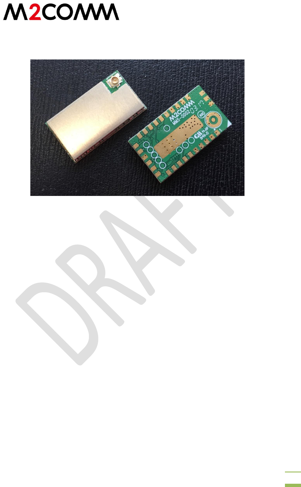
1 Product Overview
The UPLYNX-M-RCZ24 is a Sigfox Verified modem module for the low power wide area network
(LPWAN) market. It is designed with M2COMM’s Uplynx M2C8001 SOC. The module was
designed for high performance, high quality, small form factor and a low cost. The design is fully
compliant with FCC part 15.209. The Sigfox application is ported over the Uplynx M2C8001 and
executed at high efficiency using its internal 32bit core processor. Every module is preloaded
with Sigfox application software and module specific ID/KEY/PAC as specified by the Sigfox
network system. The preloaded software also includes a bootloader which allows software
updates or future user application development.
2 Product Features
Sigfox VerifiedTM RF modem (reference design fully certified)
Maximum output power: 22dBm typical
Operating Voltage: 3.4V to 5.5V (2.5V min for 20dBm+ transmission power)
Operating Temperature: -40°C to 80°C
Module enabling pin (POW_EN)
0.05µA OFF current
LGA 29 24mm x 13.5mm (RF IPEX connector) Land Grid Array
Frequency range: 902.1375-904.6625 MHz
Current consumption: 170mA continuous wave, 130mA AT$SB at 22dBm@902.2MHz

RM-UPLYNX-E003 version 1.0
Confidential and Proprietary
10
3 Functional Description
The core of the Uplynx-M-RCZ24 module is the Uplynx M2C8001 SOC. The module design is
based on the M2C8001 Sigfox VerifiedTM reference design. The Uplynx-M-RCZ24 has 6 sets of
analogue/digital multi-function pins and digital only multi-function pins. Each multi-function pin
can be configured by the user.
The Uplynx-M-RCZ24 communicates with the host MCU over a UART interface. The preloaded
UART interface firmware is configured at 9600bps baud rate, 8-bit data, no parity bit, 1 stop bit
and no flow control.
The STATUS pin indicates the activity of the Sigfox AT command interface. The module is
switched ON and OFF with the POW_EN pin. In OFF mode, the module current consumption
can be cut to its minimum (0.05µA) for longer battery operating time, an essential requirement
for Sigfox where modem activity is very low.
The RF output is a 50Ω IPEX connector and the whole module is shielded for best spurious
containment.
RM-UPLYNX-E003 version 1.0
Confidential and Proprietary
11
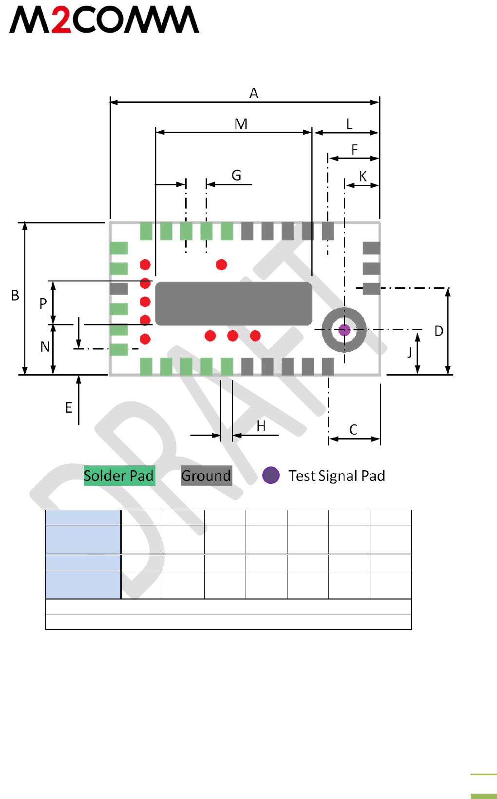
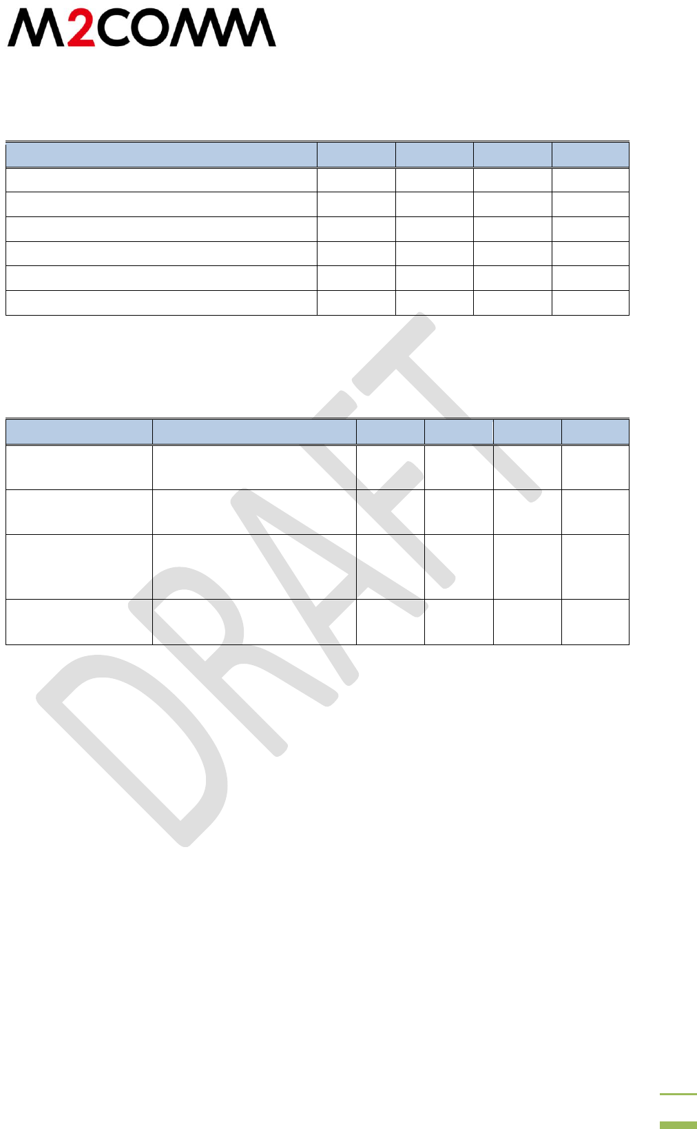
4 Pin Assignment and Package Mechanicals
Dimension
A
B
C
D
E
F
G
mm
24
13.5
4.6
7.65
2.25
4.6
1.8
TYP.
Dimension
H
J
K
L
M
N
P
mm
1.0
TYP.
4.1
3.3
5.9
14
4.5
3.9
Pad Length: 1.68 TYP.
Maximum thickness: 3.0
Figure 4-1 Bottom view of module
PCB Layout and Gerber files are available upon request
RM-UPLYNX-E003 version 1.0
Confidential and Proprietary
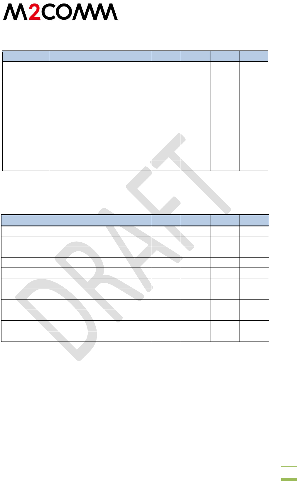
12
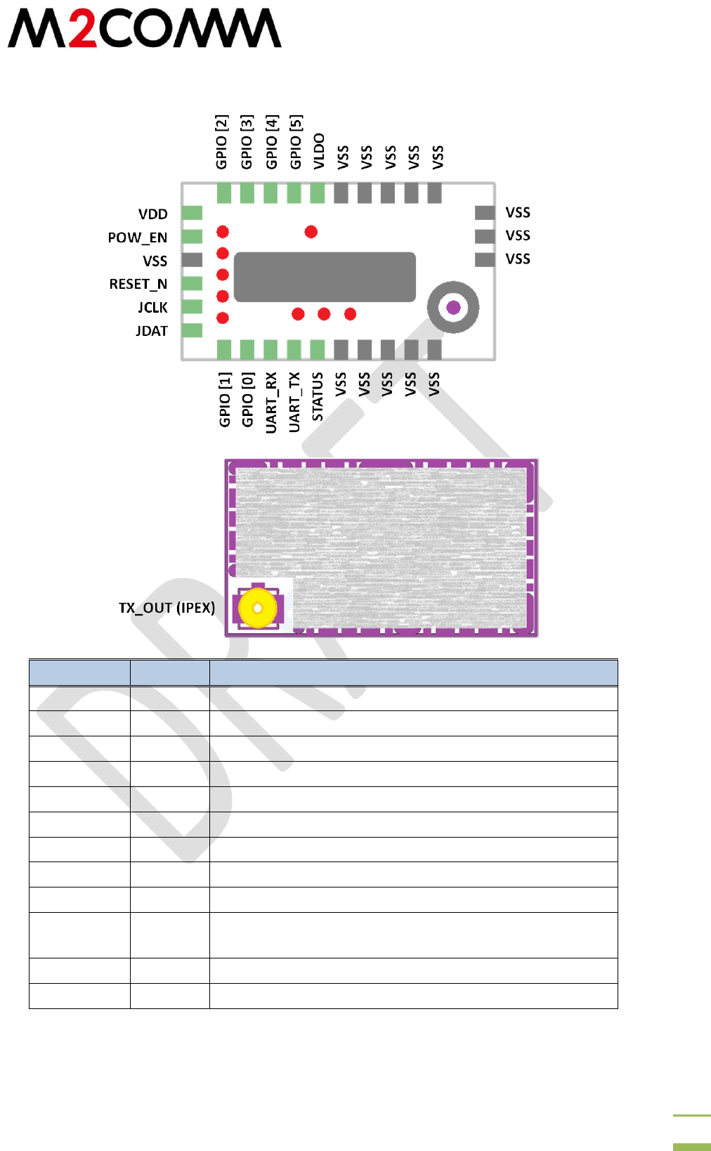
Pad Name
IO
Description
VDD
VDD
Power
VSS
GND
GND
VLDO
O
Operating voltage monitor point
RESET_N
I
Reset: When asserted LOW sets module to INITIAL state
POW_EN
I
Enable: Logic low for Disable; Logic high for Enable
UART_TX
O
UART Tx data (9600bps)
UART_RX
I
UART Rx data (9600bps)
TX_OUT
O
50Ω antenna output
GPIO [0:5]
IO
Reserved
STATUS
O
Logic High: AT Command Interface ready
Logic Low: Module busy
JDAT
I
JTAG Interface
JCLK
I
JTAG Interface
Figure 4-2 Module Pinout
RM-UPLYNX-E003 version 1.0
Confidential and Proprietary
13
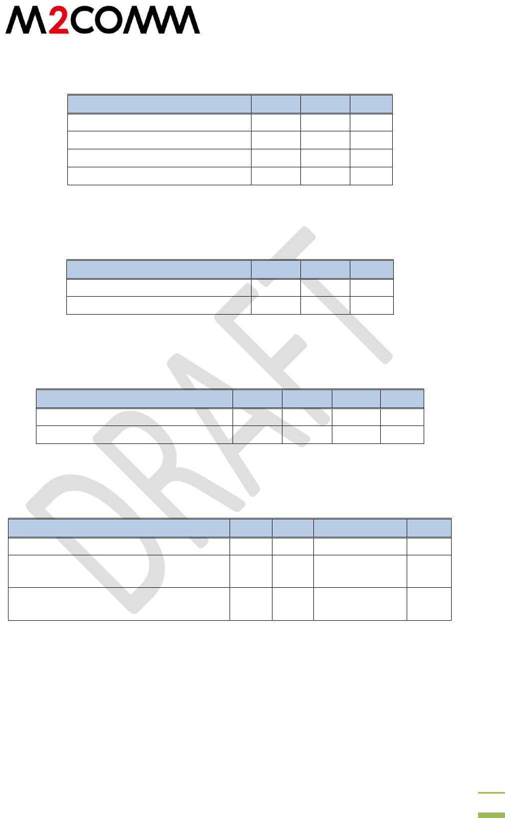
5 Electrical Specifications
Parameter
Min
Max
Unit
Power (VDD)
-0.3
5.5
V
Voltage on GPIO
-0.3
3.6
V
Storage Temperature
-40
140
°C
Maximum soldering temperature
250
°C
Table 5-1 Absolute Maximum Ratings
Parameter
Min
Max
Unit
VDD
3.4
5.5
V
Operating Temperature
-40
80
°C
Table 5-2 Recommended Operating Conditions
Parameter
Min
Typ.
Max
Unit
Off mode
0.05
1
µA
Sigfox Tx mode 902MHz 22dBm @5V
170
mA
Table 5-3 DC Current Characteristics
Parameter
Min
Typ.
Max
Unit
Output power
22
23
dBm
Harmonics conducted 915MHz 22dBm
output
FCC Compatible
dBm
Output Power deviation vs Input voltage
(2.6V ~5.5V)
1
dB
Table 5-4 Transmitter RF Performance
RM-UPLYNX-E003 version 1.0
Confidential and Proprietary
14
Parameter
Min
Typ.
Max
Unit
Reference Frequency
24
MHz
Frequency Range: High band
MHz
In-Band Phase Noise Floor
-89.77
dBc/Hz
Phase Noise @ 1MHz Offset from Carrier
-104
dBc/Hz
Settling time from power on
100
µs
Lock Time
30
µs
Table 5-5 Synthesizer Specification
Parameter
Note
Min
Typ.
Max
Unit
Calibrated
frequency
±5% course calibration
32.768
kHz
Frequency accuracy
after calibration
With software offset
adjustment routine
±1
%
Supply voltage
coefficient
Frequency drift when
supply voltage changes
after calibration
+10
%/V
Initial calibration
time
2.5
ms
Table 5-6 32kHz RC Oscillator Specification
902.1375 904.6625
RM-UPLYNX-E003 version 1.0
Confidential and Proprietary
15
Parameter
Condition/Note
Min
Typ.
Max
Unit
Crystal
Frequency
24
MHz
Crystal
Frequency
accuracy
requirement
This is the total tolerance
including
a) initial tolerance
b) crystal loading
c) aging
d) temperature dependence
The acceptable crystal tolerance
depends on RF frequency and
channel spacing / bandwidth
±20
ppm
Startup time
2
ms
Table 5-7 24MHz Crystal Oscillator Specification
Parameter
Min
Typ.
Max
Unit
Input Low Voltage
-0.3
0.8
V
Input High Voltage
2
3.6
V
Threshold point
1.36
1.45
1.55
V
Output High Voltage
2.4
V
Output Low Voltage
0.4
V
Schmitt Trigger Low to High Threshold Point
1.56
1.66
1.76
V
Schmitt Trigger High to Low Threshold Point
1.1
1.19
1.27
V
Input Leakage Current
±10
µA
Pull up resistor
42k
59k
88k
Ω
Pull down resistor
34k
54k
92k
Ω
Output current drive
20
mA
Table 5-8 Pin IO Voltage
RM-UPLYNX-E003 version 1.0
Confidential and Proprietary
16
6 Preloaded Software
The Uplynx-M-RCZ24 is loaded with the following software prior shipping:
1. Sigfox VerifiedTM Application
2. Bootloader
3. Device ID, KEY and Portable Access Code (PAC)
More detailed information can be found in document “RM-UPLYNX-E001: Uplynx AT Command
GUI and EasyAT User Guide”
6.1 Sigfox Verified AT command
The Uplynx-M-RCZ24 is designed to be compliant with the Sigfox uplink specification. The Sigfox
VerifiedTM AT command set is a standard deliverable and is used to access the network. For API
interface request, please contact our sales representatives.
The Uplynx-M-RCZ24 communicates with the host MCU over a UART interface. The UART
interface is configured at 9600bps baud rate, 8-bit data, no parity bit, 1 stop bit and no flow
control. When the AT command interface is running at startup, the pin STATUS will be pulled
high.
The following AT commands are supported.
Command
Description
Value
AT$302=pwr
Set Tx power
Pwr = Tx power [14 to 22]
AT$302?
Get current TX power
Return Current transmission power
setting
AT$400=v1,v2,v3,v4
Set Sigfox configuration
word for RCZ2 and RCZ4
settings
v1 = config_words_0
v2 = config_words_1
v3 = config_words_2
v4 = default FCC Channel
AT$400?
Inquire the Sigfox
configuration words
AT$410=mode
Enable Public Key for
emulator mode
Mode: 0-normal mode; 1- Public key
enabled (emulator mode)
AT$SB=bitvalue
Send a bit value of 0 or 1
Bitvalue = 0/1
AT$SF=frame
Send payload data, 1 to 12
bytes
Frame: data bytes (0,1,2,3…C,D,E,F)
to be sent, 12 byte maximum
AT$RC
SIGFOX_API_reset
AT$ID?
Get device ID
return ID
AT$PAC?
Get device PAC
return PAC
AT$IF=freq
Set transmission
frequency in Hz
e.g. 868000000
AT$IF?
Inquire current frequency
setting
Return frequency in Hz
AT$CW= freq, mode
Test mode with
continuous wave emission
Freq: 868000000
mode: 0-disable; 1-enable

RM-UPLYNX-E003 version 1.0
Confidential and Proprietary
17
AT$CM= packetlength
Test mode with random
data packet at fixed
frequency
Packet length = number of bytes to
be transmitted (1~26)
AT$V?
Read firmware
information
AT$O=mode, standard
Open Sigfox API library
Mode: 1 to load Sigfox library
Standard: 1-RCZ1; 2-RCZ2; 4-RCZ4
AT$RCZ=standard
Sigfox library regional
setting
Standard: 1-RCZ1; 2-RCZ2; 4-RCZ4
AT$RCZ?
Inquire Sigfox library
regional setting
Standard: 1-RCZ1; 2-RCZ2; 4-RCZ4
AT$O?
Inquire Sigfox API library
open or not
Mode: 1 to load Sigfox library
standard: 0(EU)/1(US)
AT$OOB?
Get operation condition
Return values:
[Battery voltage before active
transmission in mV]
[Battery voltage during active
transmission in mV]
[10x silicon temperature ]
e.g.
2650 [battery voltage 2.65V before
transmission]
2550 [battery voltage 2.55V during
transmission]
270 [27C silicon temperature]
AT$FW=mode
Firmware update mode
0: normal mode
1: update firmware with UART at
115200
After asserting the command, the
device needs to be rebooted into
XMODEM mode with UART speed of
115200bps. New binary can be
loaded via XMODEM protocol over
UART.
AT$GPIODIR=gpio, val
Set GPIO pin direction.
gpio = 1-GPIO0; 2-GPIO1; … , 6-
GPIO5
val: 0-input (weak pull high); 1-
output (input float)
AT$GPI=gpio
Return GPIO value
gpio = 1-GPIO0; 2-GPIO1; … , 6-
GPIO5
AT$GPO=gpio, val
Set GPIO output high or
output low
gpio = 1-GPIO0; 2-GPIO1; … , 6-
GPIO5
val: 0(output low)/1(output high)
AT$FEAT=page
Erase flash page
Page: 0 ~ 13 [EasyAT Commander
related]
AT$SIO=port
Scan GPIO input values
and execute relevant flash
Port: 6-bit input for GPIO0 to GPIO5.
A “1” represents the relevant GPIO

RM-UPLYNX-E003 version 1.0
Confidential and Proprietary
18
page
input will be scanned. [EasyAT
Commander related] e.g. port =
“100000”, GPIO0 value is scanned
and either GPIO0_Input(High) or
GPIO0_input(Low) flash page will be
executed [EasyAT Commander
related]
AT$IFVTH=voltage
Set battery detection
voltage threshold
Voltage supply is measured and the
AT command on page 12 or page 13
will be executed if the voltage is
lower and higher than the threshold
respectively [EasyAT Commander
related]
AT$DLY=count
No operation delay
Count: number of 100ms delays
Table 6-1 AT Command Set
6.2 Special Notes for Sigfox AT command interface
To load the Sigfox library for specific region X, one should set (AT$RCZ) and confirm
(AT$RCZ?) the value stored for RCZ then execute AT$O=1,X
The configuration set by the following AT commands will be stored on flash and the
value will be retained even after power off
o Transmitting frequency (i.e. AT$IF)
o Transmitting power (i.e. AT$302)
o Sigfox configuration word (i.e. AT$400)
o The following setting must be loaded to ensure normal Sigfox network activity:
RCZ2: AT$IF=902200000, AT$400=1,0,0,1
o Set RCZ region by AT$RCZ
6.3 Bootloader
The preloaded bootloader allows the user to reprogram the flash in the SOC. To enter the
firmware update mode, user can
I. Pull pin 16 low at startup (i.e. the STATUS pin of module)
On start up, the bootloader polls the module “STATUS” pin which is pin 16 of the SOC. If
the pin is logically low, the UART on the SOC is configured as 115200bps and the
bootloader is waiting for firmware via XMODEM. User can then upload the application
binary file to the SOC via XMODEM. Details can be found in “RM-UPLYNX-E001: Uplynx
AT Command GUI and EasyAT User Guide”. The application will be stored at the
application startup address and be uploaded after the system is rebooted. Details can
be found in the “Uplynx Software Development Kit User Guide”. Since the “STATUS” pin
is an output pin at normal operation, it is important to ensure the pin is NOT pulled
down by the application circuit during normal startup.
II. Enter AT$FW=1 when the Sigfox verified AT command interface is uploaded, the module
enters XMODEM mode after the AT$FW command is asserted. The speed of UART is
RM-UPLYNX-E003 version 1.0
Confidential and Proprietary
19
configurable to 115200bps. The new firmware is to be transmitted via XMODEM
protocol over UART and will be installed automatically. Upon successful update, the new
firmware will be uploaded on the next reboot. Details can be found in “RM-UPLYNX-
E001: Uplynx AT Command GUI and EasyAT User Guide”
6.4 Device ID, KEY and Portable access code
As part of the Sigfox operation requirements, each Sigfox device must be assigned a unique
identification number (ID), encryption key (KEY) and portable access code (PAC). This
information is preloaded in the module and only the ID and PAC can be read via AT command.
7 Transmission Power and Current Consumption
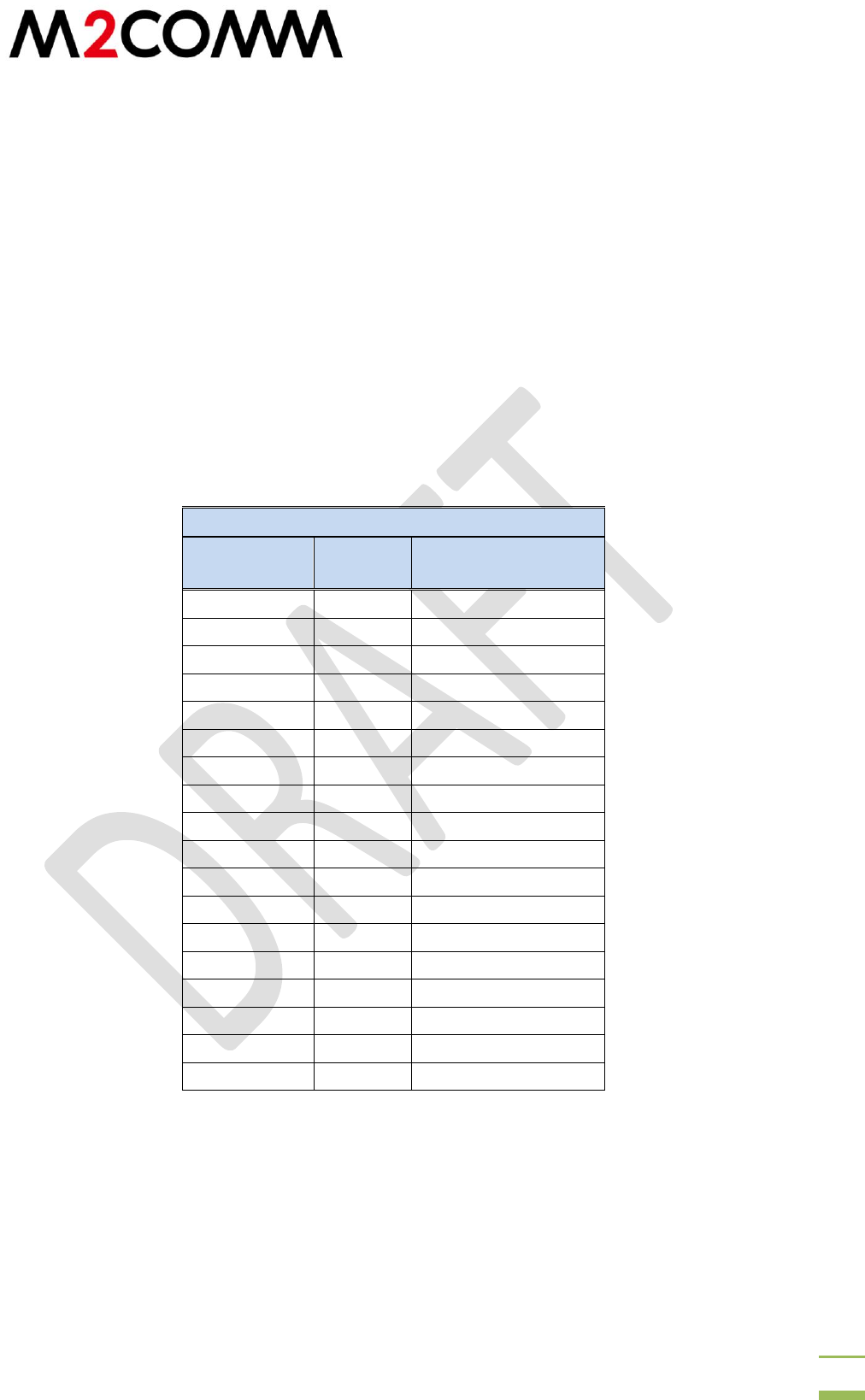
7.1 Transmission Power vs. Input Voltage
902.2MHz
VDD
Power
Current
(Continuous Wave)
5
22.3
170.6
4.5
22.3
170.6
4
22.3
170.6
3.9
22.3
170.6
3.8
22.3
170.6
3.7
22.3
170.6
3.6
22.3
170.6
3.5
22.3
170.6
3.4
22.3
170.6
3.3
22.16
167.5
3.2
21.96
163.4
3.1
21.75
159.6
3
21.53
155.9
2.9
20.31
152.5
2.8
21.06
149.3
2.7
20.8
146.1
2.6
20.5
142
2.5
20.1
135.8
Table 7-1 Recommended Pin Connections
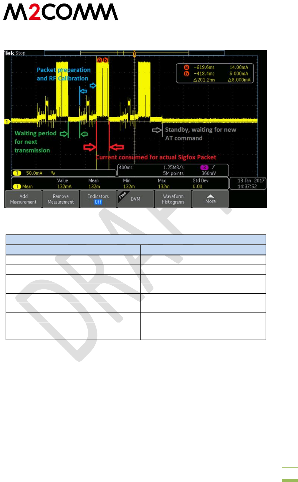
The current consumption of the Uplynx-M-RCZ24 is measured and data is presented as a
reference. The current is measured using the evaluation kit for Uplynx-M-RCZ24. Current
through J2 is measured by a Tektronix MDO3104 and a TCPA300. The module is configured for
RCZ2 and AT$SB=1 is executed to send a bit.
RM-UPLYNX-E003 version 1.0
Confidential and Proprietary
20
7.2 Current Profile and Measurement
Figure 7-1 Current Profile
VDD @ 5V, 902.2MHz
Output Power
Current
AT$302 to give
Average Current consumption AT$SB=1
14dBm
59.3mA
16dBm
70.6mA
18dBm
83mA
20dBm
124mA
22dBm
132mA
Standby Current (waiting for AT command)
2.5mA
Average current between packets (waiting
period + calibration + packet preparation)
14.5mA

RM-UPLYNX-E003 version 1.0
Confidential and Proprietary
21
8 Application Information
8.1 Mounting Considerations
Please note this module is designed for inclusion in an embedded design. If you need an off-
the-shelf solution you can purchase one of the Uplynx-M-RCZx Evaluation boards.
Surface mount board layout is a critical portion of the total design. The footprint for the module
must be the correct size to ensure proper solder connection interface between the board and
the module. With the correct pad geometry, the module will self align when subjected to a
solder reflow process.
User should surface mount the module onto their hosting PCB with all pads soldered properly.
All the control signal and ground pads must be connected properly to ensure correct operation.
8.2 Recommended connection to essential pins
PIN
Recommendation
TX_OUT
The 50Ω RF output should be connected to a pi/T antenna matching circuit
for potential antenna tuning. An ESD diode could be placed at the antenna
port to protect the product against an ESD event induced due to human
activity.
VSS
The RF performance relies strongly on a good quality ground. It is
recommended to use a ground plane if possible or thick and close ground
traces are required to minimize radiation and ensure the best RF
performance
STATUS
Can be connected to the host processor to detect module status or the pin
can lead to a status LED for displaying purposes
VDD
The voltage supply can come directly from a cell, ac adapter or USB. A
decoupling capacitor of size 10µF placed close to the 5V input is
recommended. The allowable voltage at this power input is below 5.5V
and above 2.6V.
POW_EN
It is connected to a host processor to switch on and off the modem
module.
RST_N
This can be tied to a universal reset pin or the host processor. It is
internally pulled high to VLDO. In other words, RST_N only works when
POW_EN is set high. A 10µF capacitor would be recommended in place
close to the module pin in case the supply voltage to the module. The pull
high resistance onto pin RESET_N from the system must be smaller than
50k Ω to ensure proper module startup.
VLDO
This is the output of the internal LDO of the module. This voltage supply is
used by the module RF system and it is highly recommended to leave this
pin unconnected. In case this supply is used by another part of the system,
a 1µF capacitor is recommended to be put close to the module.
Table 8-1 Recommended Pin Connections

RM-UPLYNX-E003 version 1.0
Confidential and Proprietary
22
Figure 8-1 Typical Application Circuit
8.3 Switch ON and OFF procedure
To ensure proper operation, POW_EN must be asserted high after 5V has settled then wait for
5ms before AT commands can be passed down the UART interface. The settling time is required
for the LDO and crystal oscillator to settle to their operating conditions. A software routine can
be used to poll the status of STATUS pin before any actual payload is passed to the module.
After switching the module OFF, by pulling POW_EN low, it is highly recommended that the
system should wait for at least 10ms before another attempt to power ON.
8.4 RF power and current measurement.
The Uplynx M2C8001 operates from 1.8V to 3.6V and the module is designed to leave enough
headroom for battery voltage variation and also provide maximum RF transmission power.
3.6V is selected.
With AT$302, the module transmission power is configured within the range of 14 to 22.
The transmission power and current consumption are measured and are shown below. The
user can select an appropriate power level setting to accommodate losses.
8.5 RF Grounding for FCC compliance
The Uplynx-M-RCZ24 is designed to deliver ~22dBm and is compliant to FCC emission
regulations. To achieve the tight emission limitation of the restricted bands, the grounding of
the module must be maintained by connecting all the ground pads to a large ground plan in the
PCB stack. It is highly recommended that the mother board be designed with dedicated ground
plane which connect to all the VSS pins on the module. The VSS pads must be connected to the
ground plane with a minimum of 3 vias. Decoupling capacitors must be located close to the
module supply voltage. To maximize heat dissipation, the large ground pad must be connected
RM-UPLYNX-E003 version 1.0
Confidential and Proprietary
23
to the “mother” PCB. Special care must be paid to the solder mask on the mother board to
ensure highest yield.
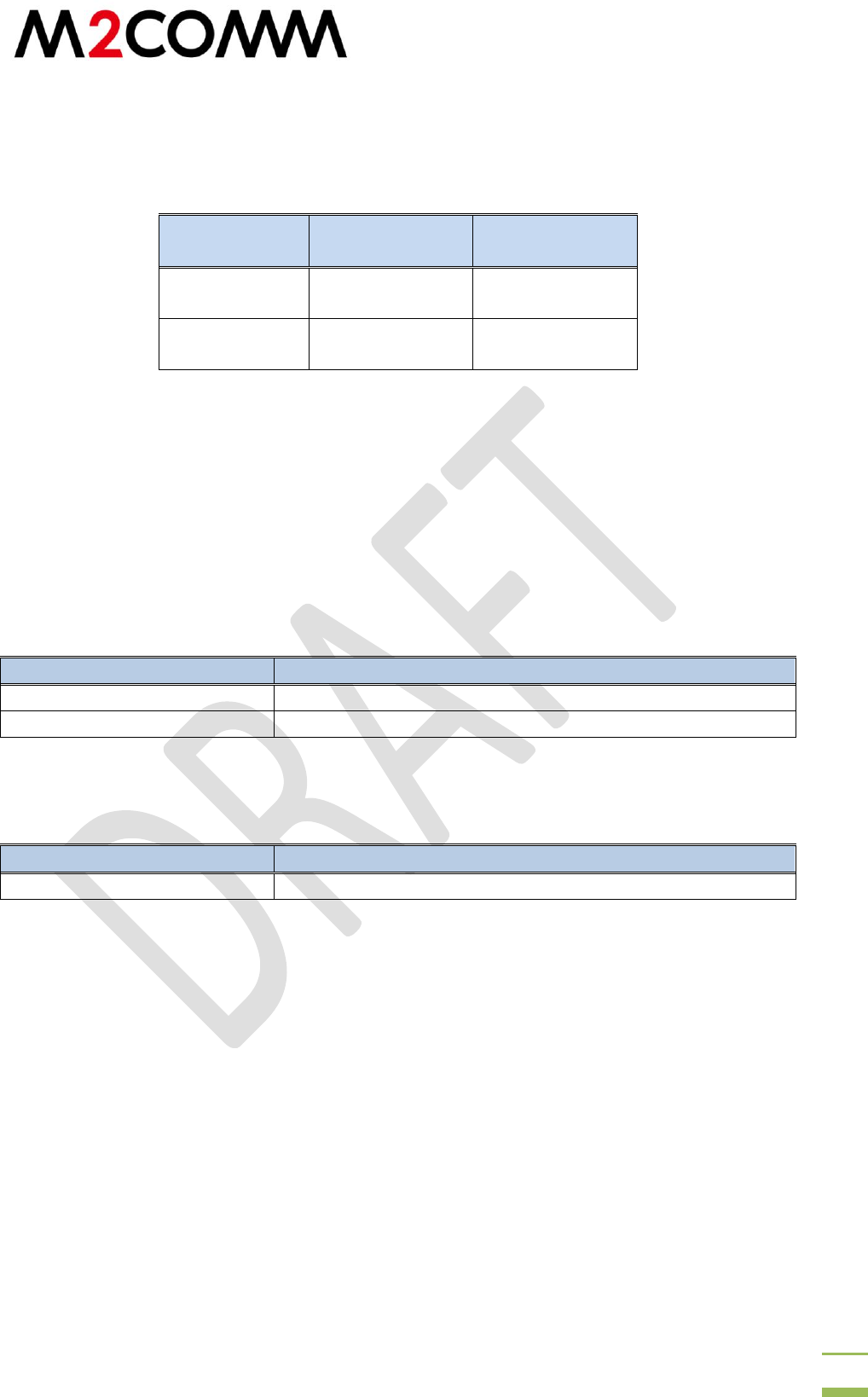
8.6 Recommended Antenna
Vendor
Part number
Type
Taoglas
TI.09.B.0151
Dipole antenna
Antenova
SRF2I019
ISM Flat Patch RF
Antenna
9 Certification
Sigfox RCZ24 reference design certification
FCC
10 Order Information
Part Number
Description
UPLYNX-M-RCZ24
Uplynx Sigfox Verified RCZ24 modem module 3.3V
UPLYNX-M-RCZ24-1.5V*
Uplynx Sigfox Verified RCZ24 modem module 1.5V
*Please contact our sales representatives for detail information.
Related products
Part Number
Description
UPLYNX-M-RCZ24-EVB
Uplynx Sigfox Verified RCZ24 modem Evaluation Kit