MAESTRO WIRELESS HER010 MAESTRO HERITAGE GSM/GPRS MODEM User Manual
MAESTRO WIRELESS HOLDINGS LIMITED MAESTRO HERITAGE GSM/GPRS MODEM Users Manual
Users Manual

www.maestro-wireless.com Email: contact@maestro-wireless.com
Tel: 852 2869 0688 Fax: 852 2525 4701
Address: Room 3603-3609, 36/F, 118 Connaught Road West, Sheung Wan, Hong Kong
Maestro Heritage
GSM GPRS Modem
850 / 900 / 1800 / 1900
USER MANUAL
Rev. 03
Confidential, the whole present document is the sole property of Maestro Wireless
Solutions Limited. 1
REVISION HISTORY
Rev. Date Details Originated by
00 11 Sept 2007 First release K.K Chan
01 04 Oct 2007 Second release K.K Chan
02 04 Jan 2008 Third release K.K Chan
03 28 Jan 2008 Fourth release Cecile Lin
This manual is written without any warranty.
Maestro Wireless Solutions Ltd. reserves the right to modify or improve the product and its
accessories which can also be withdrawn without prior notice.
Besides, our company stresses the fact that the performance of the product as well as
accessories depends not only on the proper conditions of use, but also on the environment
around the places of use.
Maestro Wireless Solutions Ltd. assumes no liability for damage incurred directly or
indirectly from errors, omissions or discrepancies between the modem and the manual.

Confidential, the whole present document is the sole property of Maestro Wireless
Solutions Limited. 2
TABLE OF CONTENTS
REVISION HISTORY.................................................................1
TABLE OF CONTENTS............................................................... 2
SAFETY PRECAUTIONS............................................................. 3
Using the modem in vehicle...................................................3
Protecting your modem.........................................................3
CHAPTER 1: Introduction .........................................................4
1. Package..........................................................................4
2. Interfaces .......................................................................4
a. Status indicator......................................................... 4
b. SMA female antenna connector ...................................5
c. 9-Pin D-Sub Female connector (RS232)........................5
d. 4-Pin connector (Power input).....................................6
3. Optional accessories.........................................................6
CHAPTER 2: INSTALLATION......................................................7
1. Install the SIM card.......................................................... 7
2. Connect the external antenna (SMA type)............................7
3. Connect the modem to external device................................8
4. Connect the DC power supply ............................................8
CHAPTER 3: WORKING WITH MAESTRO HERITAGE......................9
1. Checking the modem (using Microsoft Windows XP
HyperTerminal as example) ................................................... 9
2. Basic operation.............................................................. 11
CHAPTER 4: SPECIFICATIONS................................................. 12
CHAPTER 5: APPENDIX .......................................................... 13
CHAPTER 6: TROUBLESHOOTING ............................................ 14
1. The modem’s LED does not light....................................... 14
2. The modem’s LED lights but does not blink long time after power
up ....................................................................................14
3. The modem does not respond to the terminal program........ 14

Confidential, the whole present document is the sole property of Maestro Wireless
Solutions Limited. 3
SAFETY PRECAUTIONS
• The modem generates radio frequency (RF) power. When using the modem care must be
taken on safety issues related to RF interference as well as regulations of RF equipment.
• Do not use your phone in aircraft, hospitals, petrol stations or in places where using GSM
products is prohibited.
• Be sure that the modem will not be interfering with nearby equipment. For example:
pacemakers or medical equipment. The antenna of the modem should be away from
computers, office equipment, home appliance, etc.
• An external antenna must be connected to the modem for proper operation. Only used
approved antennas with the modem. Please contact authorized dealer on finding an
approved antenna.
• Always keep the antenna with minimum safety distance of 26.6 cm or more from human
body. Do not put the antenna inside metallic box, containers, etc.
Using the modem in vehicle
• Check for any regulation or law authorizing the use of GSM in vehicle in your country
before installing the modem
• Install the modem by qualified personnel. Consult your vehicle dealer for any possible
interference of electronic parts by the modem.
• The modem should be connected to the vehicle’s supply system by using a fuse-protected
terminal in the vehicle’s fuse box
• Be careful when the modem is powered by the vehicle’s main battery. The battery may be
drained after extended period.
Protecting your modem
• To ensure error-free usage, please install and operate your modem with care. Do
remember the following:
• Do not expose the modem to extreme conditions such as high humidity/rain, high
temperatures, direct sunlight, caustic/harsh chemicals, dust, or water.
• Do not try to disassemble or modify the modem. There is no user serviceable part inside
and the warranty would be void.
• Do not drop, hit or shake the modem. Do not use the modem under extreme vibrating
condition.
• Do not pull the antenna or power supply cable. Attach/ detach by holding the connector.
• Connect the modem only according to the instruction manual. Failure to do it will void
the warranty.
Confidential, the whole present document is the sole property of Maestro Wireless
Solutions Limited. 4
CHAPTER 1: Introduction
Maestro Heritage is a ready-to-use GSM modem for data, fax and SMS services. It also
supports GPRS (Class 10) and EDGE for hi-speed data transfer. Maestro Heritage can be easily
controlled by using AT command for all kinds of operations. With standard 9 - pin RS232 port,
the Maestro Heritage can be set up with minimal effort.
Maestro Heritage also having an Expansion Slot to make the modem becomes even more
powerful. Add-on unit such as Input/Output, Ethernet Router and GPS etc…
1. Package
The Maestro Heritage package should include the following:
- Maestro Heritage x 1
- Power cord with fuse x 1
- Safety note x 1
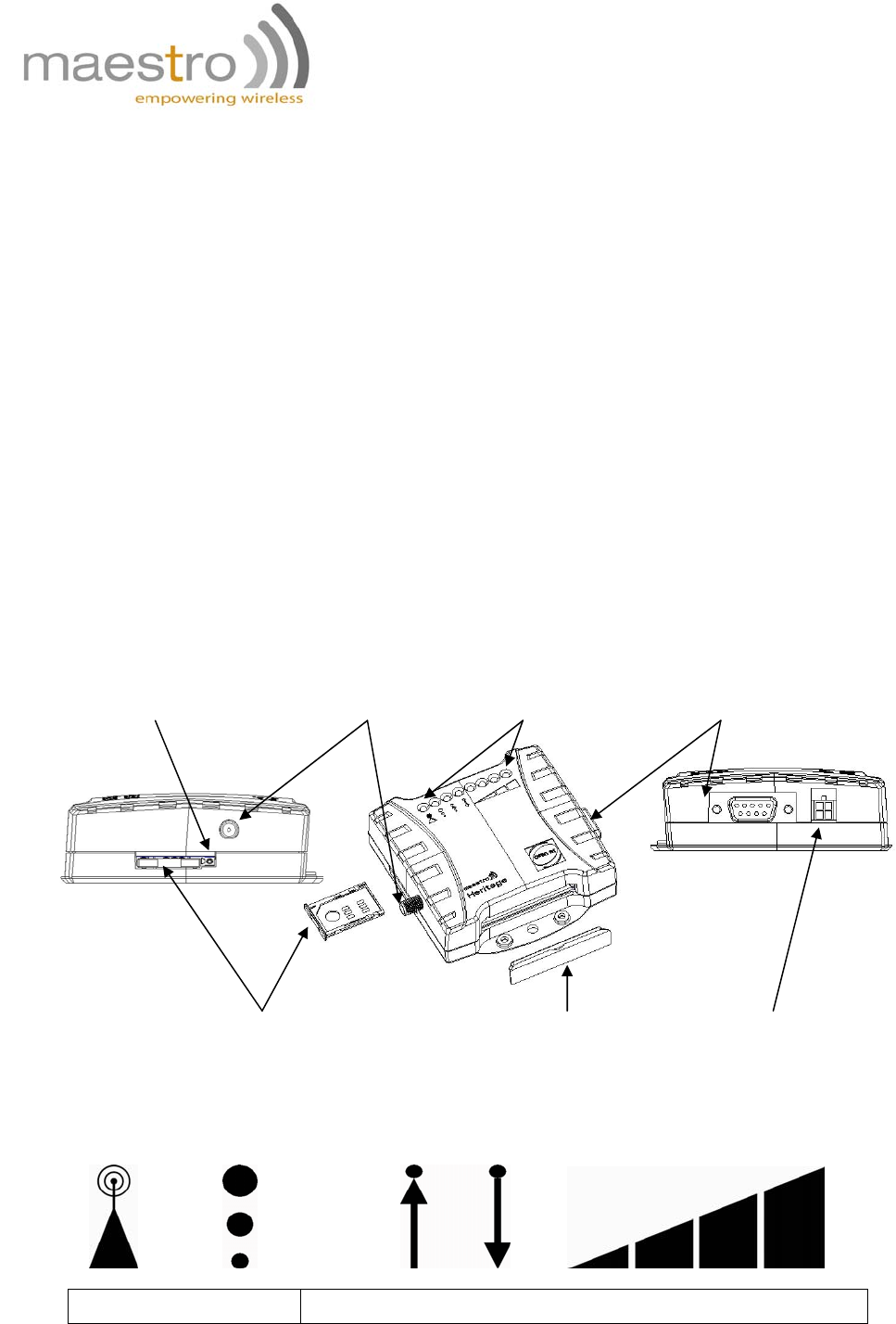
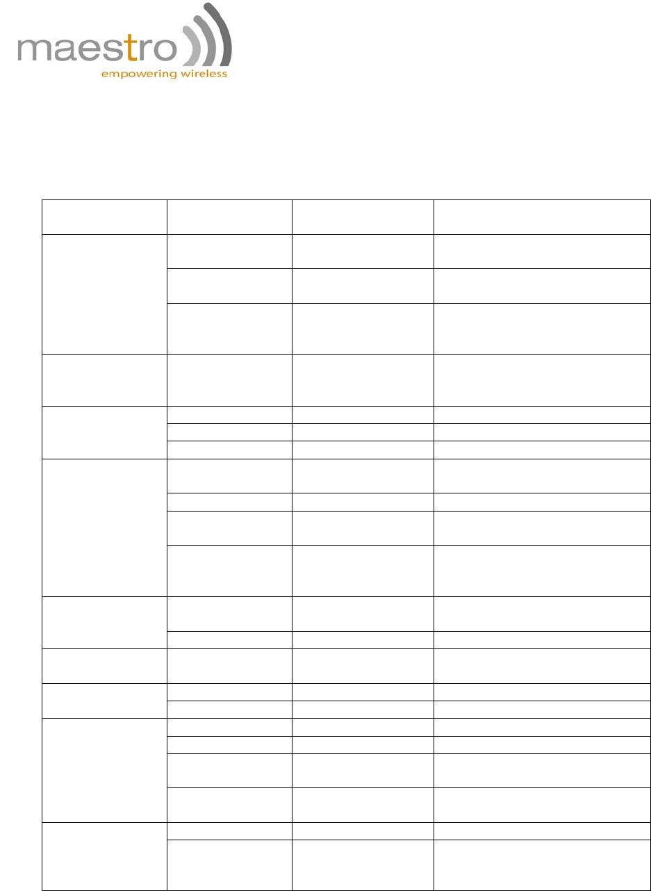
2. Interfaces
a. Status indicator
The LED will indicate different status of the modem:
ON/OFF EDGE Rx Tx Signal Strength
Name Descriptions
SIM holder Rubber
cover 4-PIN connector (Power
input)
9 pin Sub-D Female
Connector (RS232)
Status
indicator
SMA female antenna
connector
SIM holder
eject button
Confidential, the whole present document is the sole property of Maestro Wireless
Solutions Limited. 5
Sub-D 9
p
in
Signal Strength Strong (CSQ 27 or higher)
Signal Strength Medium (CSQ 23 – 26)
Signal Strength Low (CSQ 14 – 22)
Signal Strength Weak (CSQ 1 – 13)
Rx Data receive over TCP/UDP
Tx Data transmit over TCP/UDP
EDGE Availability of EDGE
GSM Status OFF – Modem is off
On – Modem is not registered to GSM network
Slow blinking – Modem is registered to GSM network
Fat blinking – Modem is in GSM communication
b. SMA female antenna connector
Connect this to an external antenna with SMA male connector. Make sure the antenna is
for the GSM 900 / 1800 or GSM 850 / 1900 frequency with impedance of 50ohm, and also
connector is secured tightly.
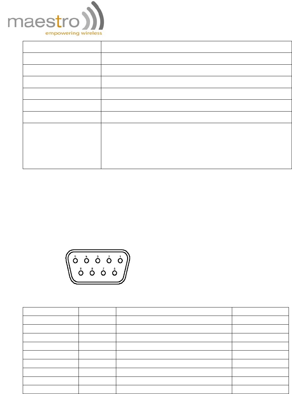
c. 9-Pin D-Sub Female connector (RS232)
The connector provides serial link to the modem
Pin number Name EIA designation Type
1 DCD Data Carrier Detect Output
2 RXD Receive Data Output
3 TXD Transmit Data Input
4 DTR Data Terminal Ready Input
5 GND Ground Ground
6 DSR Data Set Ready Output
7 RTS Request To Send Input
8 CTS Clear To Send Output
9 RI Ring Indicator Output
Confidential, the whole present document is the sole property of Maestro Wireless
Solutions Limited. 6
RS232 Cable
- Direct connection with standard 9-pin
RS-232 port (DTE)
- Shielded cable
- Cable length 1.1m (w/ connector)
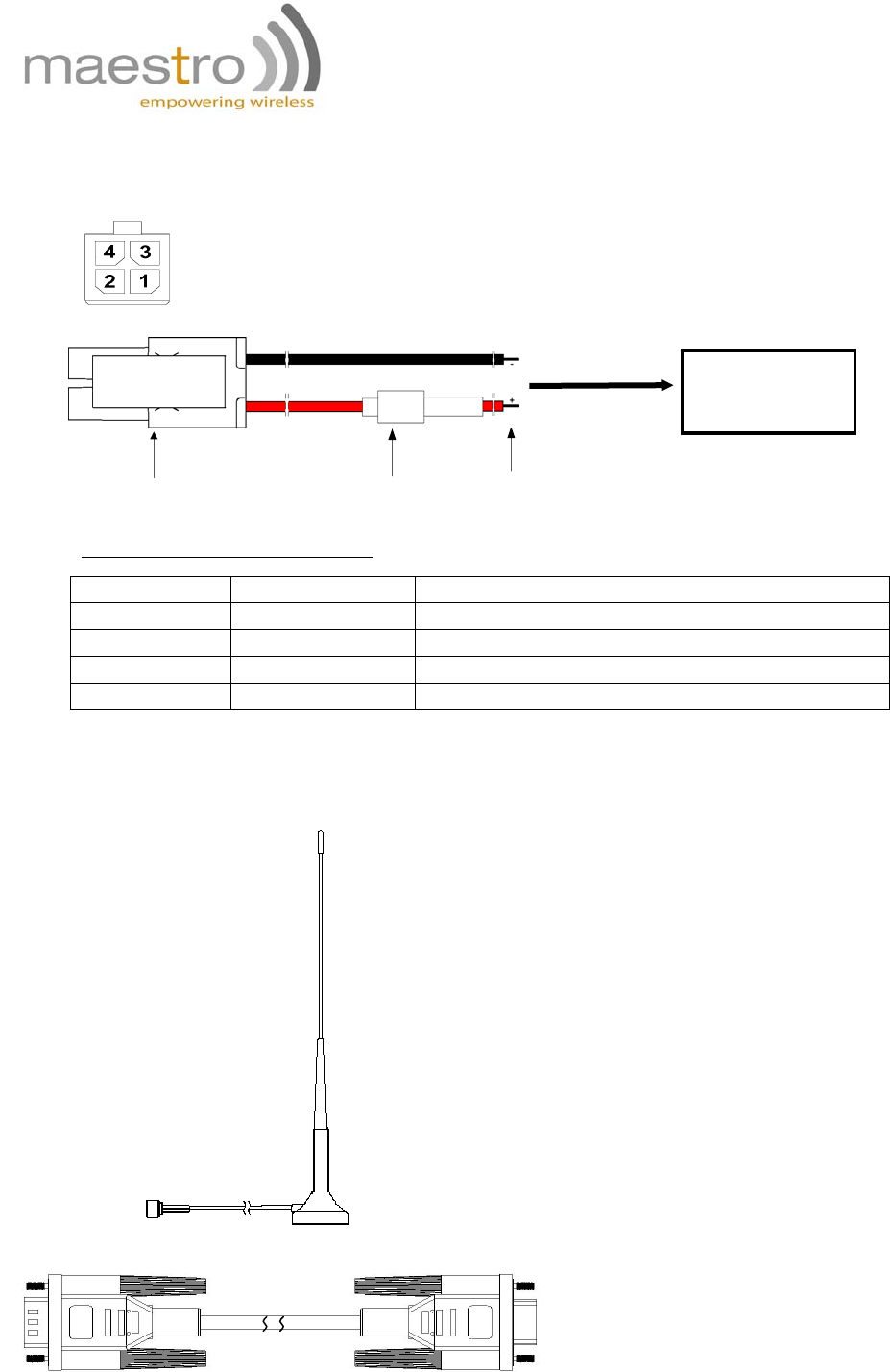
d. 4-Pin connector (Power input)
A cable, included in the package shall be used for power supply connection:
Pin assignment of 4-Pin connector
Pin number Name Functions
1 Not used None
2 Not used None
3 POWER - DC power negative input
4 POWER + DC power positive input
3. Optional accessories
You may contact your sales agent for the following optional accessories:
Fuse
Connector Micro-Fit 3.0
(to Fargo Maestro) Stripped wire
5-32V DC
Supply
External antenna
- Magnetic mount type
- Frequency GSM 900/1800 band (3dBi)
- Frequency GSM 850 / 1900 band (0dBi)
- VSWR < 1.5:1
- Height ~ 236 mm (including magnetic base)
- Cable: Type RG-174U length 2.5m
- SMA male connector on cable end
- Color: back (SMA connector silver)
Confidential, the whole present document is the sole property of Maestro Wireless
Solutions Limited. 7
CHAPTER 2: INSTALLATION
1. Install the SIM card
Use a ball pen or paper clip to press the SIM holder eject button. The SIM holder will come out
a little. Then take out the SIM holder.
Note: DO NOT pull out the SIM holder without pushing the ejector.
Put the SIM card to the tray; make sure it has completely sat on the tray. Put the tray back into
the slot.
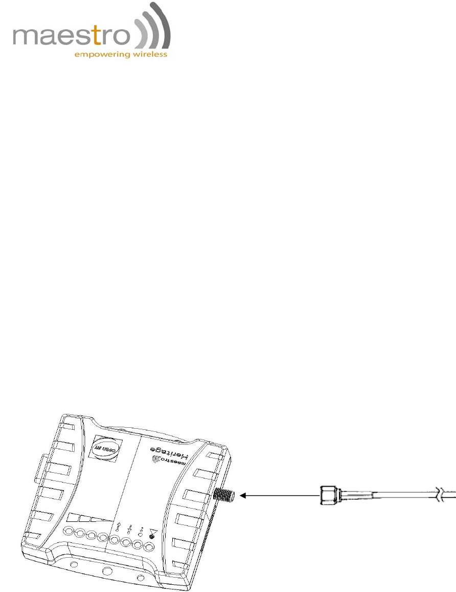
2. Connect the external antenna (SMA type)
Connect this to an external antenna with SMA male connector. Make sure the antenna is for the
GSM 900/1800 or GSM 850 / 1900 frequency with impedance of 50ohm, and also connector is
secured tightly.
Note: Please use antenna designed for GSM 900/1800 or GSM 850 / 1900 MHz operation.
Incorrect antenna will affect communication and even damage the modem.
Secure
tightly
SMA male connector of antenna
Confidential, the whole present document is the sole property of Maestro Wireless
Solutions Limited. 8
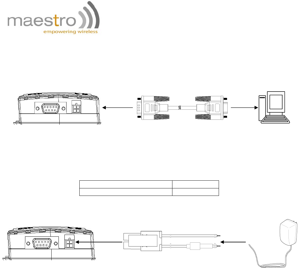
3. Connect the modem to external device
You can use the RS232 cable to connect the modem's Sub-D connector to external
controller/computer.
Connection example using RS232 cable:
4. Connect the DC power supply
Connect the open ending of the inducted power cord to a DC supply. Refer to the following for
power supply requirement.
Input voltage range 5V – 32V
Rated current 500 mA
Connect the connector to the modem. The modem will turn on automatically.
The status indicator on the modem will be lit when power on. After a few seconds it will go
flashing slowly (registered to the network successfully refer 1.2.1).
Heritage Sub-D 9 pin
DB-9
RS-232 Port of
PC
Solder wire
AC-DC
Adaptor or
battery
Confidential, the whole present document is the sole property of Maestro Wireless
Solutions Limited. 9
CHAPTER 3: WORKING WITH MAESTRO HERITAGE
1. Checking the modem (using Microsoft Windows XP
HyperTerminal as example)
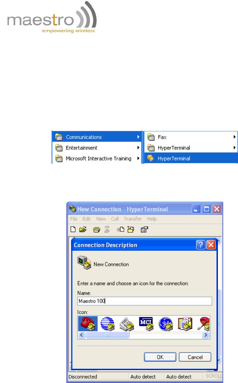
a. On the first time power-up you can use terminal software to communicate with
the modem through an RS232 serial port. Following example is using the
HyperTerminal in Windows XP.
b. On Windows XP, start the HyperTerminal program. Assign a name for a new
session.
Confidential, the whole present document is the sole property of Maestro Wireless
Solutions Limited. 10
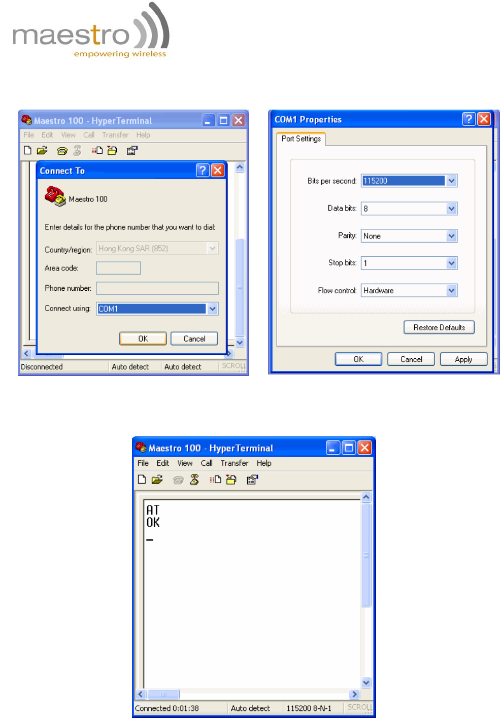
c. Choose the correct Com port and baud rate settings (9600bps for Eco;
115200bps for others, 8bits, no parity bit, 1 stop bit)
d. On the terminal screen, type "AT" to check the "OK" response from the
modem
Confidential, the whole present document is the sole property of Maestro Wireless
Solutions Limited. 11
2. Basic operation
Followings are examples of some AT commands. Please refer to the AT command document
for a full description.
Note: Issue AT+CMEE=1 to have extended error code (+CME ERROR)
Description AT commands
Modem
response Comments
AT+CREG? CREG=<mode>,1
Modem registered to the
network
CREG=<mode>,2
Registration lost,
re-registration attempt
Network
registration
checking
CREG=<mode>,0
Modem not registered on the
network, no registration
attempt
Receiving
signal strength AT+CSQ +CSQ:20,0 The first parameter has to be
at least 15 for normal
communication
RING An incoming call is waiting
ATA Answer the call
Receiving an
incoming call OK
ATD1234567; Don’t forget the “;” at the
end for “voice” call
OK Communication established
CME ERROR : 11 PIN code not entered (with
+ CME = 1 mode)
Make a call
CME ERROR : 3 AOC credit exceeded or a
communication is already
established
ATD 112; Don’t forget the “;” at the
end for “voice” call
Make an
emergency call OK
Communication
loss NO CARRIER
ATH Hang up OK
AT+CPIN=1234
OK PIN Code accepted
+CME ERROR : 16
Incorrect PIN code (with
+CME = 1 mode)
Enter PIN code
+CME ERROR : 3 PIN already entered (with
+CME = 1 mode)
AT&W Saves
parameters in
non-volatile
memory
OK The configuration settings
are stored
Confidential, the whole present document is the sole property of Maestro Wireless
Solutions Limited. 12
CHAPTER 4: SPECIFICATIONS
• Quad-Band GSM 850 / 900 / 1800 /1900 MHz
• Support Data, Voice and Fax
• ETSI GSM Phase 2 + compliant
• LED Bar indication of RSSI, Network Registration, Up/Down data Traffic and
EDGE availability
• Group 3 FAX support (Class 1 and 2)
• GPRS Class 10
• Real time clock backup by Super-Capacitor
• Built-in watchdog chip to prevent modem lock-up
• Control via AT command (GSM 07.05, GSM 07.07 and WAVECOM proprietary)
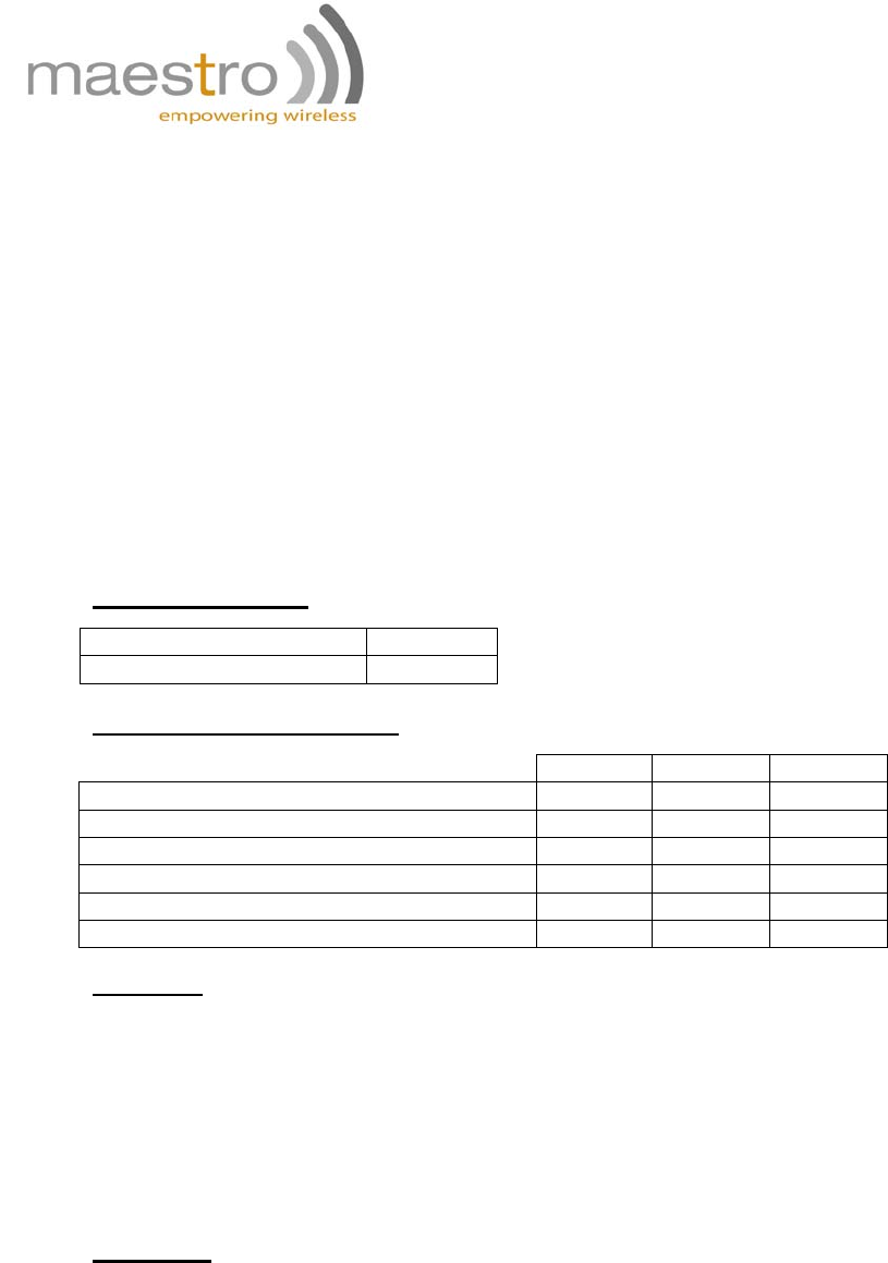
Power requirements:
Input voltage range 5V - 32V
Rated current 500 mA
Typical current consumption:
@5V @12V @32V
GSM900 communication mode PCL=5 310mA
130mA
50mA
DCS1800 communication mode PCL=5 240mA
100mA
40mA
GPRS900 class 10 PCL=5 520mA
220mA
80mA
GPRS1800 class 10 PCL=0 390mA
160mA
70mA
Idle mode 80mA 35mA 18mA
Idle mode with power saving 75mA 34mA 15mA
Interfaces:
• SIM Holder
• 9 pin sub-D connector
• 4 pin power supply connector
• SMA antenna connector (50 Ohm)
• Din rail mountable
• Expansion slot for add-on module for customized functions
Dimensions
• Overall size: 79mm x 84mm x 27mm
• Weight: 100g
• Temperature range: -20°C to +55°C Operating ETSI compliant
-35°C to +85°C Operating functional
-40°C to +85°C Storage
Confidential, the whole present document is the sole property of Maestro Wireless
Solutions Limited. 13
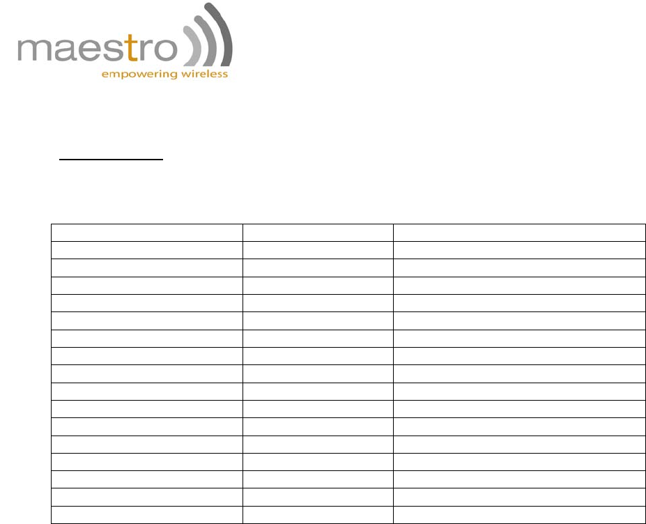
CHAPTER 5: APPENDIX
Factory settings
The modem has the following factory settings. Please refer to the AT command document for
the meaning of each setting.
Related AT commands Factory settings
Description
AT+IPR 115200 DTE-DCE data rate
AT+IFC 2,2 DTE-DCE flow control
AT+ICF 3,4 DTE-DCE character framing
ATE 1 ECHO
AT&C 1 DCR signal
AT&D 2 DTR signal
ATQ 0 Result code suppression
ATV 1 Response format
AT&S 1 DSR signal
ATS0 0 Auto answer
AT+CLIP 0 Calling line ID presentation
AT+CRLP Calling line ID restriction
AT+CSCS “PCCP437”
AT+CMGF 1 Message format
AT+CSMP 1,67,0,0 Test mode parameters
AT+CNMI 0,1,0,0 New message indication

Confidential, the whole present document is the sole property of Maestro Wireless
Solutions Limited. 14
CHAPTER 6: TROUBLESHOOTING
1. The modem’s LED does not light
Check if the modem has been properly connected to a 5 - 32V power supply
Check if the power connector is properly inserted
Check the fuse on the power cord
2. The modem’s LED lights but does not blink long time
after power up
Check if a valid SIM card has been properly inserted
Check if the SIM card has been locked (refer to AT+CPIN command in AT command guide)
Check if the external has been properly connected to the modem
Check if the network coverage is available
3. The modem does not respond to the terminal program
Check if the RS232 cable has been properly connected
Check if your program has proper settings. Factory setting of the modem is:
• 115200
• 8 data bits
• No parity bit
• 1 stop bit
CHAPTER 7: RF exposure information
To maintain compliance with FCC RF exposure requirements, use handset that maintain a
20cm separation distance between the user's body and the host and antenna. MPE limit for RF
exposure at prediction frequency is 0.558mW/cm2 for GSM850MHz and 1mW/cm2 for
GSM1900MHz. The MPE for GSM850MHz is 0.488mW/cm2 and 0.277mW/cm2 for
GSM1900MHz. It satisfies RF exposure compliance.