MAGIC CHEF Microwave/Hood Combo Manual L0803304
KOG-574R L0803304
User Manual: MAGIC MAGIC CHEF Microwave/Hood Combo Manual MAGIC CHEF Microwave/Hood Combo Owner's Manual, MAGIC CHEF Microwave/Hood Combo installation guides
Open the PDF directly: View PDF ![]() .
.
Page Count: 8
Microwave Oven
Installation Manual
Introduction
Your Over-the-Range ruicrowave oven corues complete with an installation instruction kit which contains the followilrg tln'ee pieces of information
required to install it.
I. This installation instruction booklet,
complete with diagrams on prepaxing yonr
cabinets and microwave oven for
installation.
The Top Cabinet Template, used to locate
the power cord clearance hole, cabinet
ruounting holes and the vertical exhaust
location.
III. Instead of The Wall Monnt Template,
Wall Monnting Plate, used to locate the
monnting plate holes and to locate the
horizontal exhaust location.
Please read all of the instructions
thoronghly before installing your
nlicrowave oven.
NOTE:
IT IS RECOMMENDED THAT TWO
PEOPLE INSTALL THIS PRODUCT.
IMPORTANT:
KEEP INSTRUCTIONS FOR LOCAL
ELECTRICAL INSPECTOR'S USE.
Important Safety Information
Grounding Instructions
This appliance must be _ounded. In the event of an electrical short circuit,
gounding reduces the risk of the electric shock by providing an escape
wire tbr the electric cm'rent.This appliance is equipped with a cord having
a m'oundingwire with a g'ounding plug. The plug must be plugged into an
outlet that is properly installed and _ounded.
WARNING - Improper use ofthe grounding can result in a risk of electric
shock.
Consult a qualified electrician or serviceman if the grounding instructions
are not completely understood, or if doubt exists as to whether the
appliance is properly _ounded, and either:
1) If it is necessary to use an extension cord, use only a 3-wire extension
cord that has a 3-blade _'ounding plug, and a 3-slot receptacle that will
accept the plutg on the
appliance. The marked rating of
the extension cord shall be equal
to or greater than the electrical
rating of the appliance, or Do not
use an extension cord.
2) If the power supply cord is too
short, have a qualified ".\_
electrician or serviceman \,
install an outlet near the
appliance.
Safety Instructions
This product requires a three prong _'ounded receptacle. The installermust
pertbrm a _'ound continuity check on the power outlet box before
beginning the installation to insure that the outlet box is properly _ounded.
If not properly grotmded, or if theoutlet box does not meet the electrical
requirements noted, (under ELECTRICAL REQUIREIVIENTS),a
qualified electrician should be employed to correct any deficiencies.
CAUTION: FOR PERSONAL SAFETY, REMOVE HOUSE FISE
OR OPEN CIRCUIT BREAKER BEFORE BEGINLNING
INSTALLATION TO AVOID SEVERE OR FATAL SHO(K
INJI RY. CAUTION:FOR PERSONAL SAFETY, THE
MOUNTING S[_ACE _HTST BE CAPABLE OF SUPPORTING
THE CABINET LOAD, LNADDITION TO THE ADDED WEIGHT
OF THIS 85 POI_'D PRODUCT, PLUS ADDITIONAL OVEN
LOADS OF IP TO 50 POUNDS OR A TOTAL WEIGHT OF 135
POUN3)S.
CAUTION: FOR PERSONAL SAFETY THIS PRODUCT
CANLNOTBE INSTALLED TO CABINET ARRANGEMENT'S
SUCH AS AN ISLAND OR A PENINSULA. IT MUST BE
MO[ NTED TO BOTH A TOP ( ABINET AND AWALL.
Electrical Requirements
Product rating is 120 volts AC, 60Hertz, 14.6 amps, and 1.60 kilowatts.
This product must be connected to a supply circuit of the proper voltage
and frequency. Wke size nmst confol_ to the requirements of the National
Electric Code or the prevailing local code for this kilowatt rating. The
power supply cord and plug should be brought to a separate 20ampere
branch circuit single _'ounded receptacle. The outlet box should be located
near the cord entry point. The outletbox and supply ckcuit should be
installed by a qualified electrician and conform to the National Electric
Code or the prevailing local code.
Power supply cord
a) A shortpower-supply cord is provided to reduce the risks resulting from
becoming entangled in or tripping over a longer cord.
b) Longer cord sets or extension cor& are available and may be used if
care is exercised in their use.
c) Ifa long cord or extension cord is used:
1) The marked electrical rating of the cord set orextension cord should
be at least as _m'eatas the electrical rating of the appliance.
2) The extension cord nmst be a grounding type 3-wire cord, and
3) The longer cord should be arranged so that it will not &ape over the
counter top or tabletop where it can be pulled on by children or
tripped over unintentionally.
This over-the-range oven was designed for use over ranges no wider
than 30inches. It may be installed over both gas and deetrie cooking
equipment.
Installation Hardware
The following is a list of parts you may
need for installing your Over-the-Range
microwave oven. You will find them
packaged inside the microwave cooking
cavity. Remove all parts from the oven
cavity and compare them with the parts
®
list and illustration to be sure that none
are missing. Use this time to become
familiar with each piece.
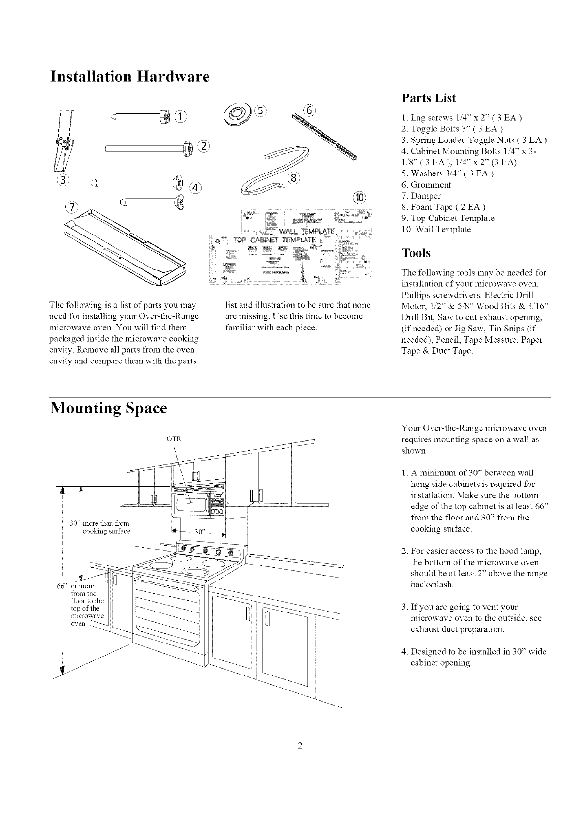
Parts List
1. Lag screws 1/4" x 2" ( 3 EA )
2. Toggle Bolts 3" ( 3 EA )
3. Spring Loaded Toggle Nuts ( 3 EA )
4. Cabinet Mounting Bolts 1/4" x 3-
1/8" ( 3 EA ), 1/4" x 2" (3 EA)
5. Washers 3/4" ( 3 EA )
6. Gromment
7. Damper
8. Foam Tape ( 2 EA )
9. Top Cabinet Template
10. Wall Template
Tools
The %llowing tools may be needed %r
installation of your microwave oven.
Phillips screwdrivers, Electric Drill
Motor, 1/2" & 5/8" Wood Bits & 3/16"
Drill Bit, Saw to cut exhaust opening,
(if needed) or Jig Saw, Tin Snips (if
needed), Pencil, Tape Measure, Paper
Tape & Duct Tape.
Mounting Space
OTR
'1
30" more than from
cooking surface
66" O£ lllore
floratile
floorto the
topof the
Your Over-the-Range microwave oven
requires mounting space on a wall as
shown.
1. A minimum of 30" betaveen wall
hung side cabinets is required for
installation. Make sure the bottom
edge of the top cabinet is at least 66"
from the floor and 30" from the
cooking surface.
2. For easier access to the hood lamp,
the bottom of the microwave oven
should be at least 2" above the range
backsplash.
3. If you are going to vent your
microwave oven to the outside, see
exhaust duct preparation.
4. Designed to be installed in 30" wide
cabinet opening.
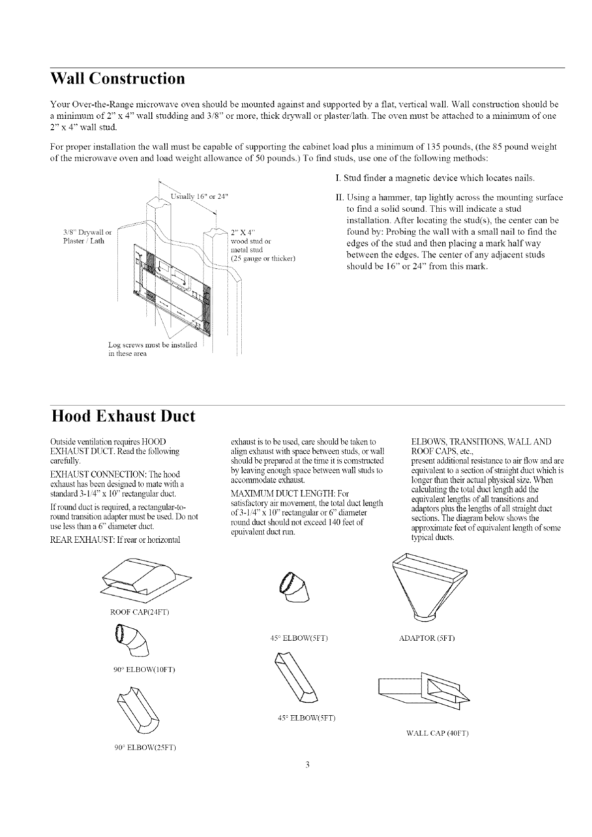
Wall Construction
Your Over-the-Range microwave oven should be mounted against and supported by a flat, vertical wall. Wall construction should be
a minimum of 2" x 4" wall studding and 3/8" or more, thick drywall or plaster/lath. The oven must be attached to a minimum of one
2" x 4" wall stud.
For proper installation the wall must be capable of supporting the cabinet load plus a minimum of 135 pounds, (the 85 pound weight
of the microwave oven and load weight allowance of 50 pounds.) To find studs, use one of the following methods:
3/8" DiTwall or
Plaster /Lath
Usually 16"or 24"
r
_/_"'_: 2" X 4"
wood studor
::metal stud
(25 gaugeor thicke*)
I. Stud finder a magnetic device which locates nails.
II. Using a hammer, tap lightly across the mounting surface
to find a solid sound. This will indicate a stud
installation. After locating the stud(s), the center can be
found by: Probing the wall with a small nail to find the
edges of the stud and then placing a mark halfway
between the edges. The center of any adjacent studs
should be 16" or 24" from this mark.
Log sclews must be installed : iI
in these area
Hood Exhaust Duct
Outside ventilation requires HOOD
EXHAUST DUCT. Read the tbllowing
carefully.
EXHAUST CONNECTION: The hood
exhaust has been desigled to mate with a
standard 3-1/4" x 10" rectangular duct.
If round duct is required, a rectaugular-to-
round trausition adapter nmst be used. Do not
use less thau a 6" diameter duct.
REAREXHAUST:Ifrearor horizontal
ROOF CAP(24FT)
%
90 ° ELBOW(10FT)
90° ELBOW(25FT)
exhaust is to be used, care should be taken to
alignexhaust with space between studs, or wall
should be prepared at the time it is comstmcted
by leaviug euough space between wall studs to
accolmnodate exhaust.
MAXIIVRJMDUCT LENGTH: For
satisfactory air movement, the total duct length
of 3-1 '4" x 10" rectaugular or 6" diameter
round duct should not exceed 140 feet of
epuNalent duct run.
45° ELBOW(5FT)
45° ELBOW(5FT)
ELBOWS, TRANSITIONS, WALL AND
ROOF CAPS, etc.,
preseut additional resistance to air flow and are
equivaleut to a sectiou of straight duct which is
longer than their actual physica! size. When
calculatiug the total duct len_h add the
equivaleut lengths of all transitions and
adaptors plus the leugths of all straight duct
sections. The diagram below shows the
approximate feet of equivalent length of some
typical ducts.
ADAPTOR (5FT)
WALL CAP (40FT)
Ventilation system Instructions
Your Over-the-Range microwave oven is designed for adaptation to the following three types of ventilation.
Select the type of ventilation required for your installation and proceed to the appropriate section.
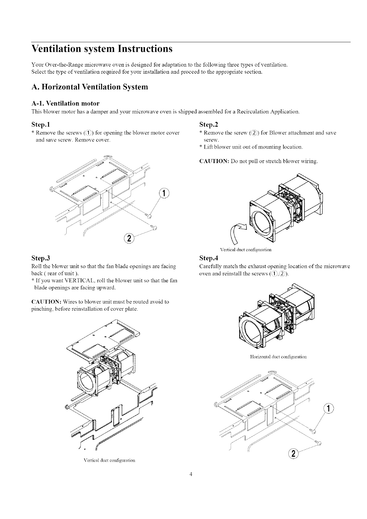
A. Horizontal Ventilation System
A-1. Ventilation motor
This blower motor has a damper and your microwave oven is shipped assembled for a Recirculation Application.
Step.1
* Remove the screws (11))for opening the blower motor cover
and save screw. Remove cover.
Step .2
* Remove the screw (_) for Blower attachment and save
screw.
* Lift blower unit out of mounting location.
CAUTION: Do not pull or stretch blower wiring.
Step .3
Roll the blower unit so that the fan blade openings are facing
back ( rear of unit ).
* If you want VERTICAL, roll the blower unit so that the fan
blade openings are facing upward.
CAUTION: Wires to blower unit must be routed avoid to
pinching, before reinstallation of cover plate.
Vel_ical duct configulation
Step .4
Carefully match the exhaust opening location of the microwave
oven and reinstall the screws (]).,: 2)).
Horizontal duct configmation
Veltical duct configmation
A-2. Install the Mounting Plate
Step. 1 Setup position
a. Draw a line down the middle of the studs(See the Wall Construction_ page 3)
b. Draw a vertical line on the wall at the center of the 30" wide space.
NOTE: Use the wall template for the rear wall.
Reference \Vail Template prior to proceeding.
Installation of this product require TXVO persons.
Step. 2 Drilling
Reference the Wall Template.
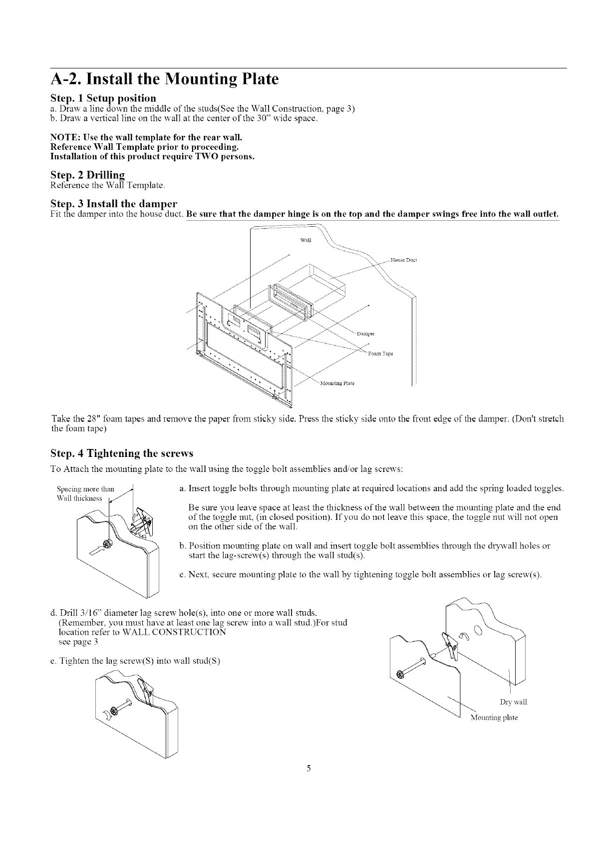
Step. 3 Install the damper
Fit the damper into the house duct. Be sure that the damper hinge is on the top and the damper swings free into the wall outlet.
I Wall _.
_jjl/, "" - 21222____o House Duct
Take the 28" foam tapes and remove the paper from sticky side. Press the sticky side onto the front edge of the damper. (Don't stretch
the foam tape)
Step. 4Tightening the screws
To Attach the mounting plate to the wall using the toggle bolt assemblies and/or lag screws:
Spacing more than
Wall thickness a. Insert toggle bolts through mounting plate at required locations and add the spring loaded toggles.
Be sure you leave space at least the thickness of the wall between the mounting plate and the end
of the toggle nut, (in closed position). If you do not leave this space, the toggle nut will not open
on the other side of the wall.
b. Position mounting plate on wall and insert toggle bolt assemblies through the drywall holes or
start the lag-screw(s) through the wall stud(s).
c. Next, secure mounting plate to the wall by tightening toggle bolt assemblies or lag screw(s).
d. Drill 3/16" diameter lag screw hole(s), into one or more wall studs.
(Remember, you must have at least one lag screw into a wall smd.)For stud
location refer to WALL CONSTRUCTION
see page 3
e. Tighten the lag screw(S) into wall stud(S)
Diy wail
Mortaring plate
A-3. Mounting microwave oven
NOTE: IT IS VERY IMPORTANT THAT THIS OVEN BE INSTALLED BY TWO PEOPLE.
PREPARATION OF TOP CABINET
You need to drill holes for the top support screws and a hole large enough for the power cord to fit through.
• Read the instructions on the TOP CABINET TEMPLATE
• Tape it underneath the top cabinet
• Drill the holes, following the instructions on the template
CABLNET
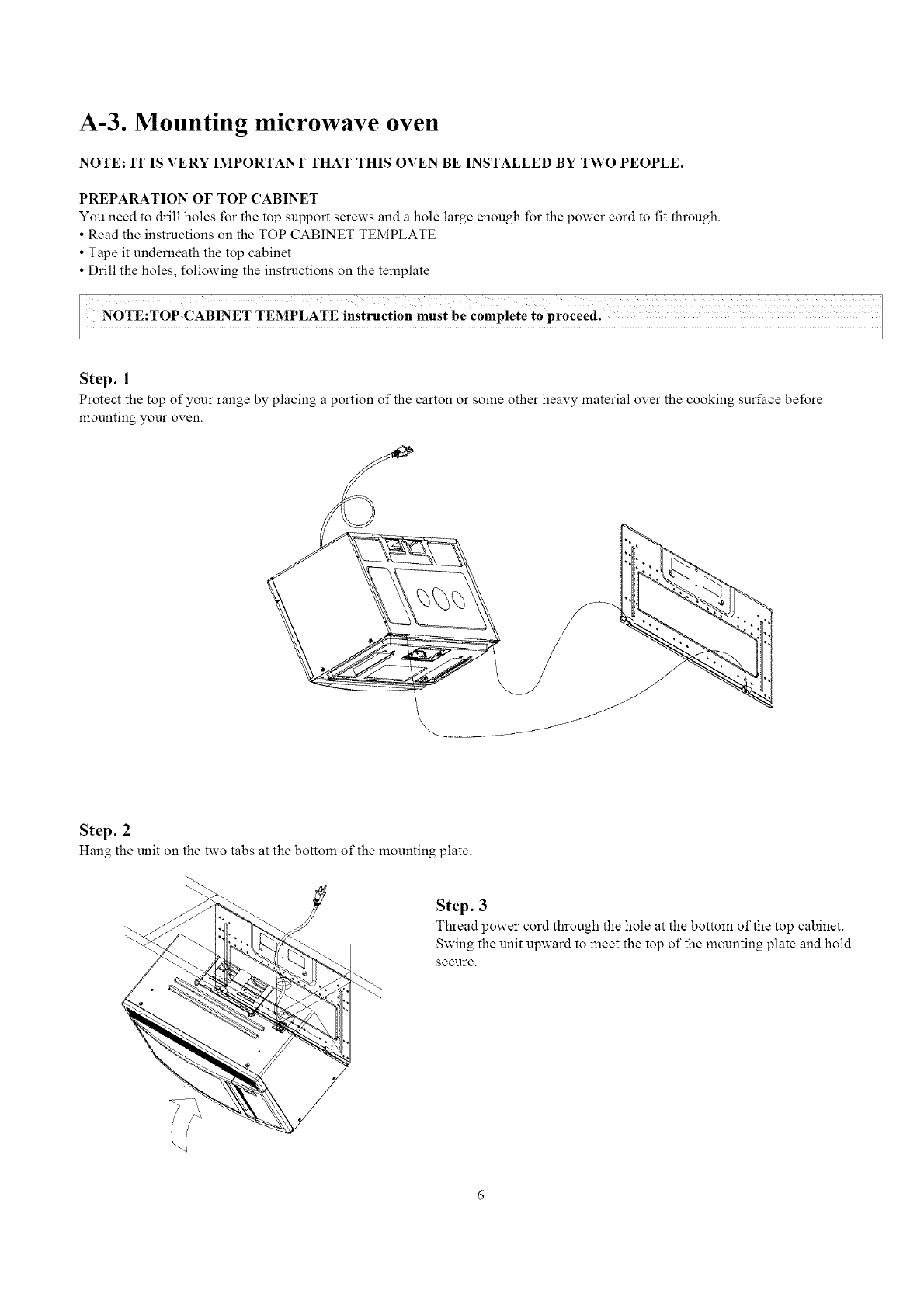
Step. 1
Protect the top of your range by placing a portion of the carton or some other heavy material over the cooking surface before
mounting your oven.
Step. 2
Hang the unit on the two tabs at the bottom of the mounting plate.
Step. 3
Thread power cord through the hole at the bottom of the top cabinet.
Swing the unit upward to meet the top of the mounting plate and hold
secure.
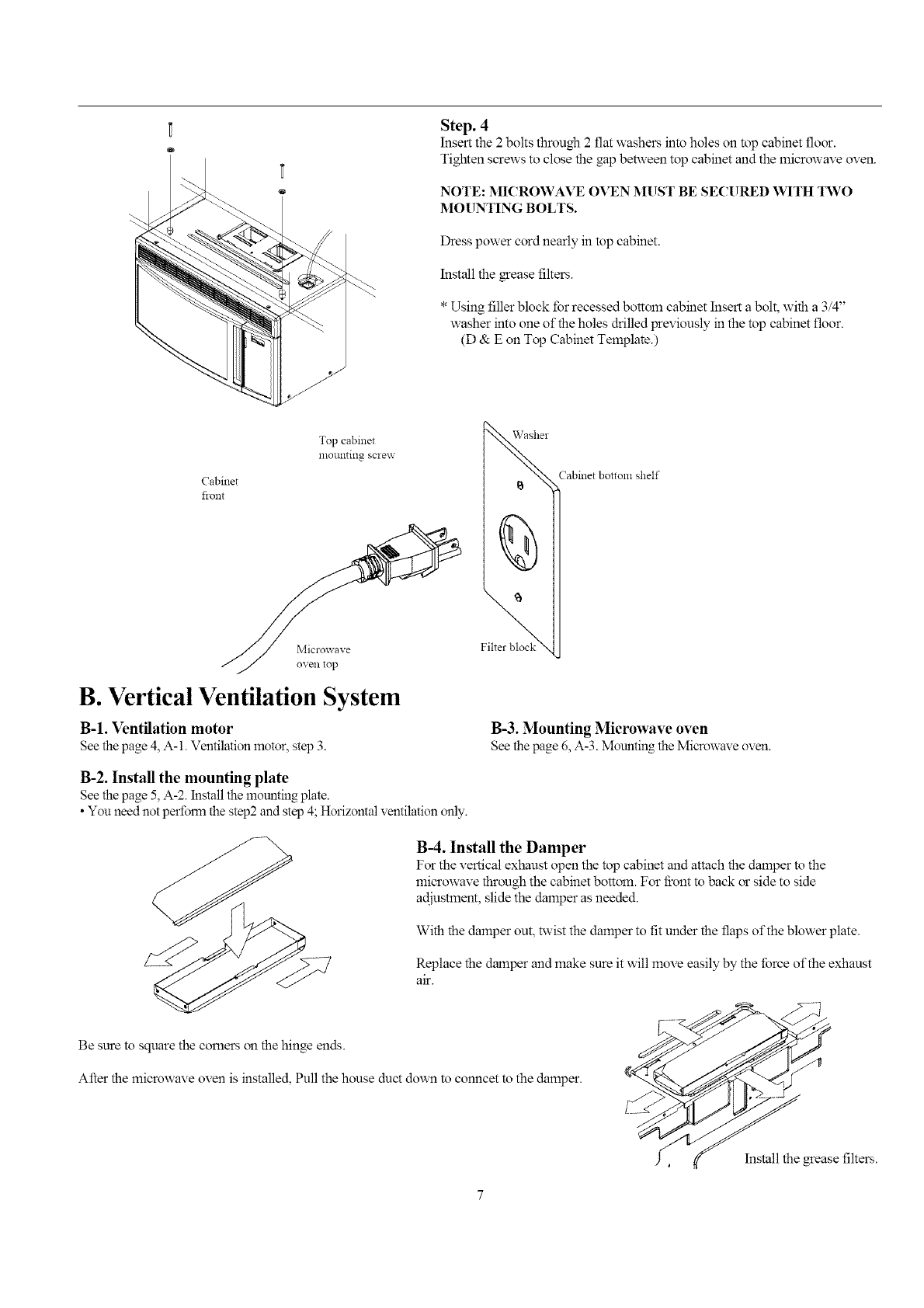
Step. 4
Insert the 2 bolts through 2 flat washers into holes on top cabinet floor.
Tighten screws to close the gap between top cabinet and the microwave oven.
NOTE: MICROWAVE OVEN MUST BE SECURED WITH TWO
MOUNTING BOLTS.
Dress power cord nearly in top cabinet.
Install the _ease filters.
* Using filler block for recessed bottom cabinet Insert a bolt, with a 3/4"
washer into one of the holes drilled previously in the top cabinet floor.
(D & E on Top Cabinet Template.)
Cabinet
flont
Topcabinet
nlOtlll_illg sclew
Microwave
oven top
B. Vertical Ventilation System
B-1. Ventilation motor
See the page 4, A-1. Ventilation motor, step 3.
B-2. Install the mounting plate
See the page 5, A-2. Install the mounting plate.
• Yon need not pertbnn the step2 and step 4; Horizontal ventilation only.
\Vashel
Cabinet bottom shelf
B-3. Mounting Microwave oven
See thepage 6, A-3. MountingtheMicrowaveoven.
B-4. Install the Damper
For the vertical exhaust open the top cabinet and attach the damper to the
microwave through the cabinet bottom. For front to back or side to side
adjustment, slide the damper as needed.
With the damper out, twist the damper to fit under the flaps of the blower plate.
Replace the damper and make sure it will move easily by the force of the exhaust
air.
Be sure to square the comers on the hinge ends.
After the microwave oven is installed, Pull the house duct down to conncet to the damper.
Install the _ease filters.
C. Recirculation Ventilation System
Your over the range microwave oven has been provided with a charcoal filter for a recirculation venting application. If replacement of
the charcoal filter is required, contact your MAYTAG authorized dealer.
C-1. Ventilation motor
This ventilation motor has been assembled for Recirculation exhaust.
C-2. Install the Mounting plate
See the page 5, A-2. Install the mounting plate.
• You need not perform the step 2 and step 4; Horizontal ventilation
only.
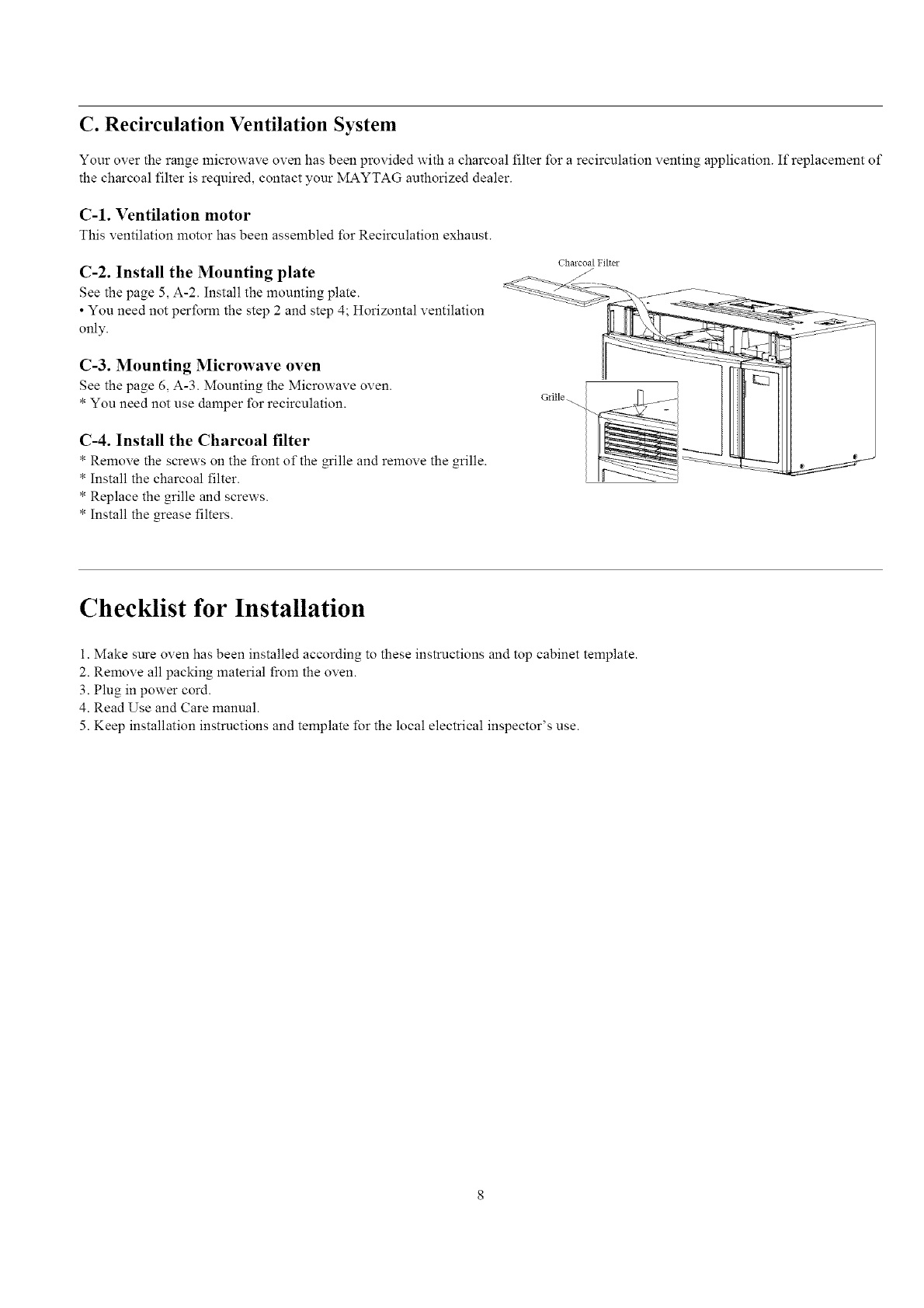
C-3. Mounting Microwave oven
See the page 6_ A-3. Mounting the Microwave oven.
* You need not use damper for recirculation.
Chalcoal Filter
Glille.
C-4. Install the Charcoal filter
*Remove the screws on the front of the grille and remove the grille.
* Install the charcoal filter.
* Replace the grille and screws.
* Install the grease filters.
Checklist for Installation
1. Make sure oven has been installed according to these instructions and top cabinet template.
2. Remove all packing material from the oven.
3. Plug in power cord.
4. Read Use and Care manual.
5. Keep installation instructions and template for the local electrical inspector's use.
