MANN HUMMEL SPB358 OurAir Duct Air Quality Monitor User Manual
MANN HUMMEL (China) Co., Ltd. OurAir Duct Air Quality Monitor Users Manual
UserManual.wiki
>
MANN HUMMEL
>
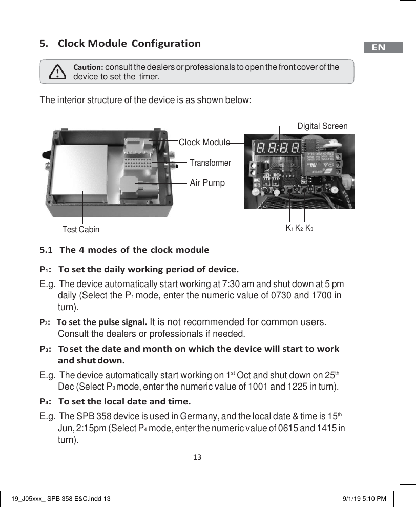
SPB358 User Manual
Users Manual
Navigation menu
Upload a User Manual
Namespaces
Wiki Guide
HTML
PDF
Info
Views
User Manual
Discussion / Help
Navigation