MARKEM CIMJETRFID Frequency Hopping RFID Tag Reader User Manual 00 Cimjet RFID Rev A EN
MARKEM Corporation Frequency Hopping RFID Tag Reader 00 Cimjet RFID Rev A EN
UserManual.wiki
>
MARKEM
>
CIMJETRFID User Manual
Exhibit D Users Manual per 2 1033 b3
Navigation menu
Upload a User Manual
Namespaces
Wiki Guide
HTML
PDF
Info
Views
User Manual
Discussion / Help
Navigation
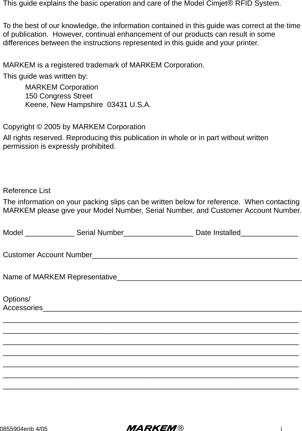
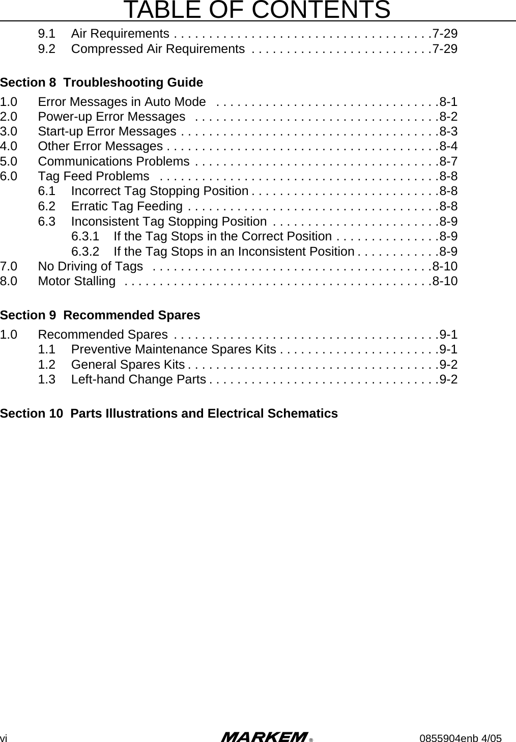
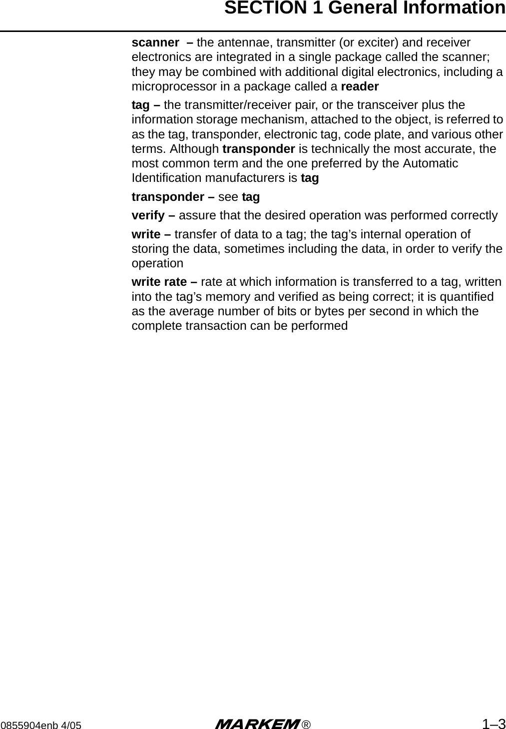


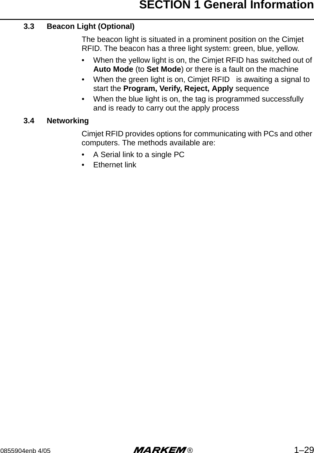
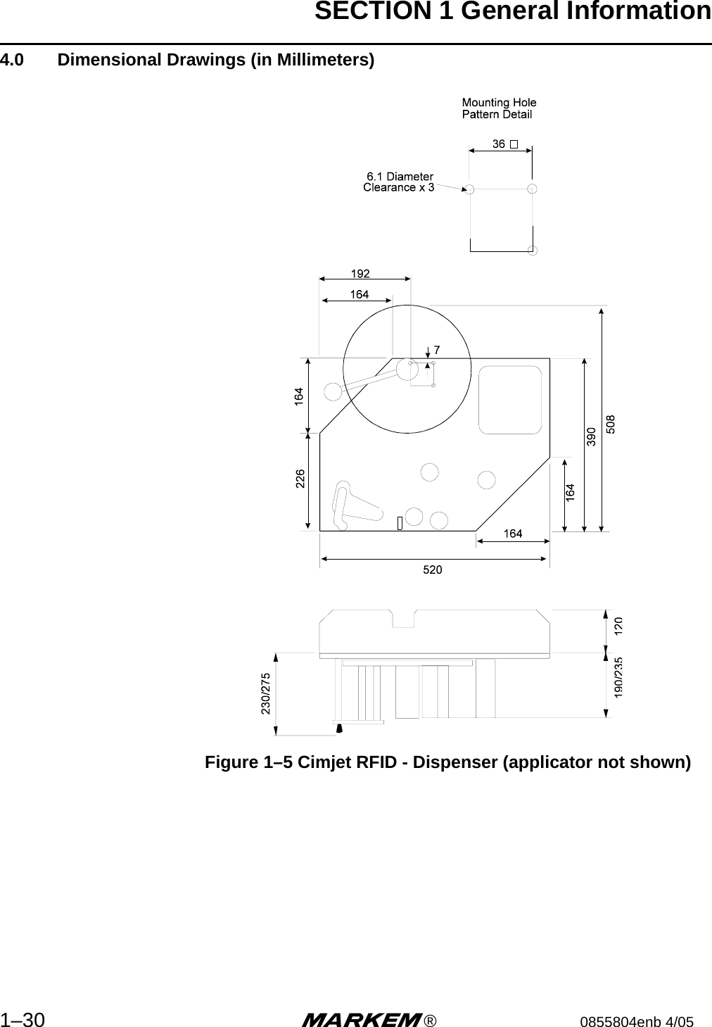

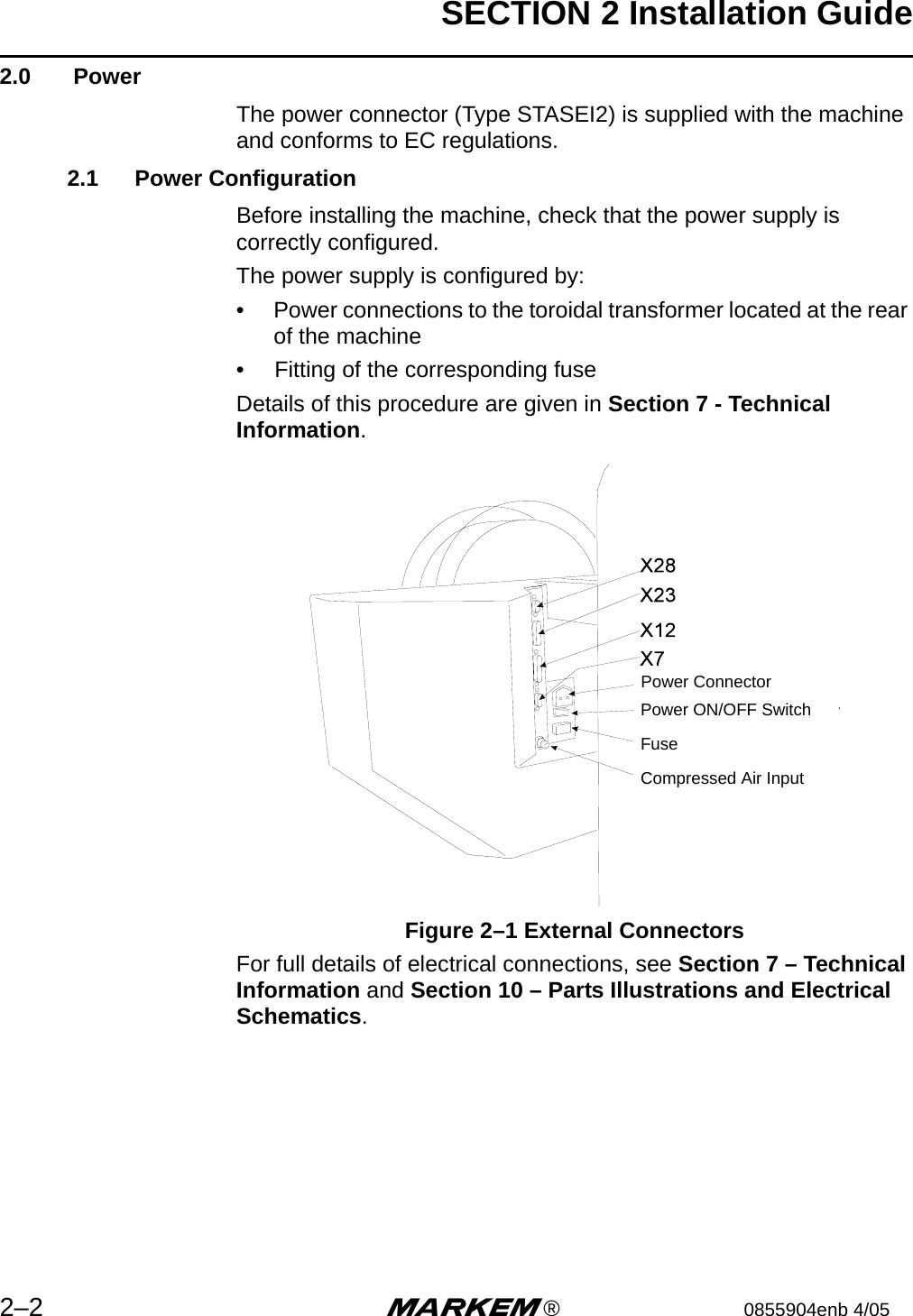

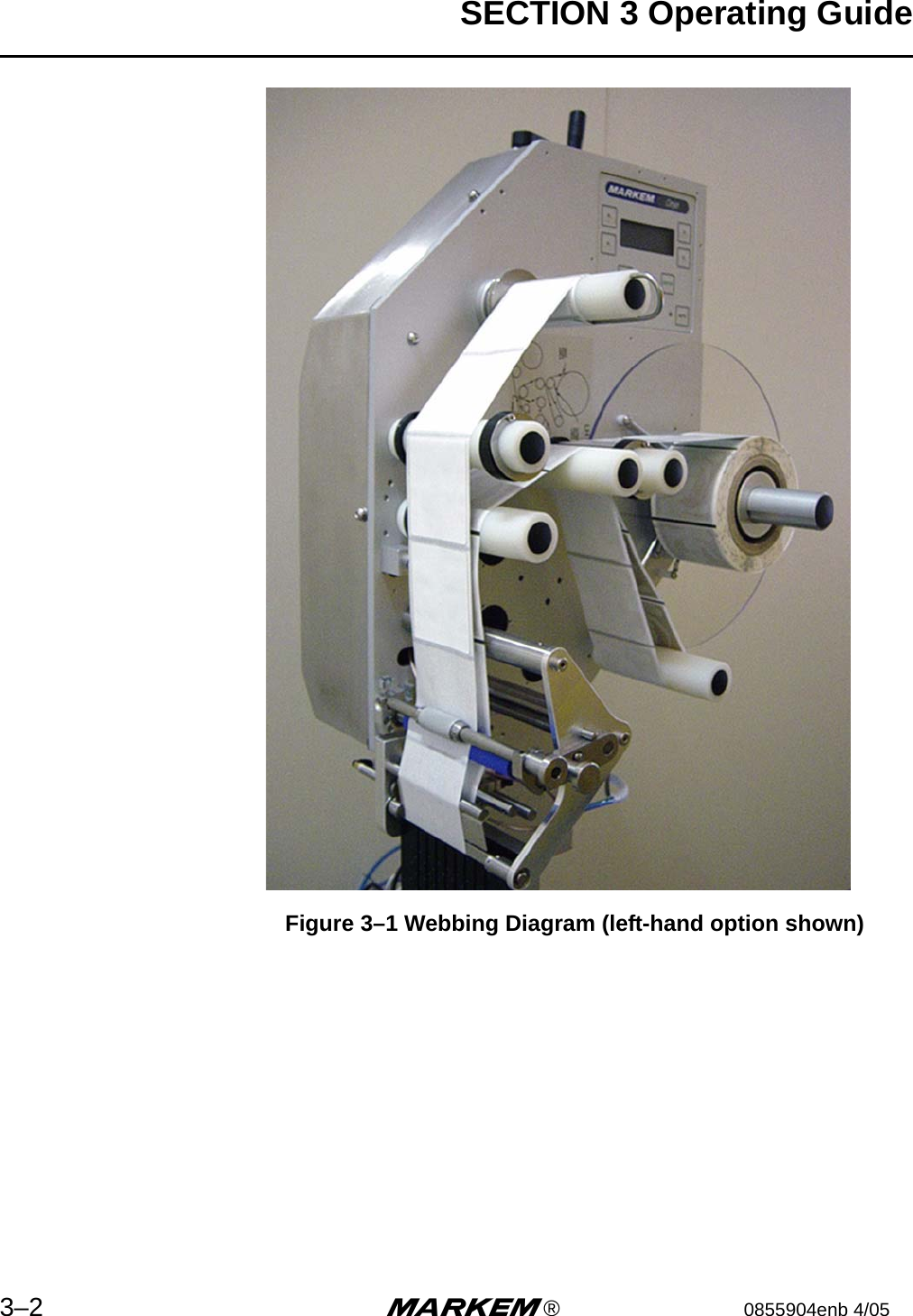
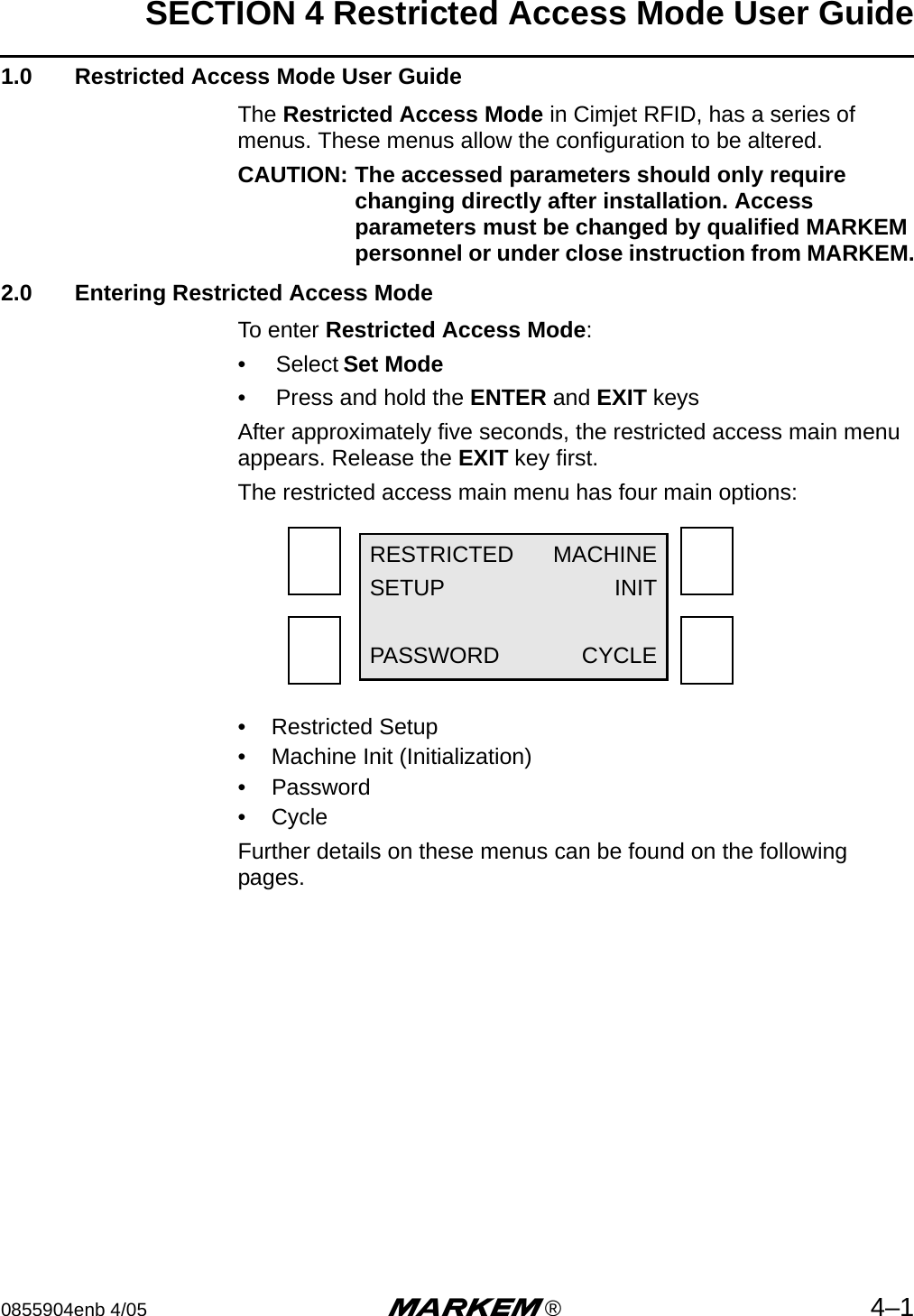

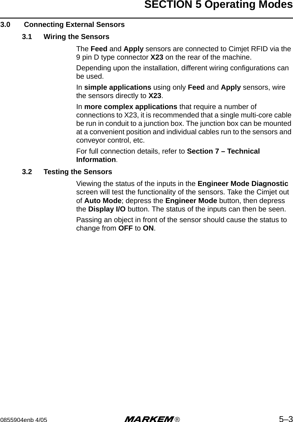


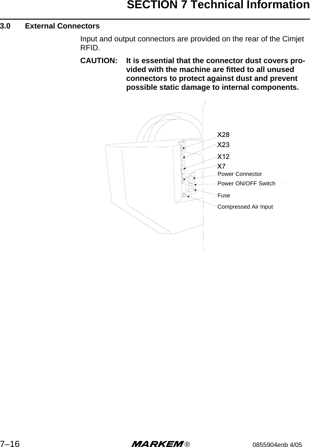
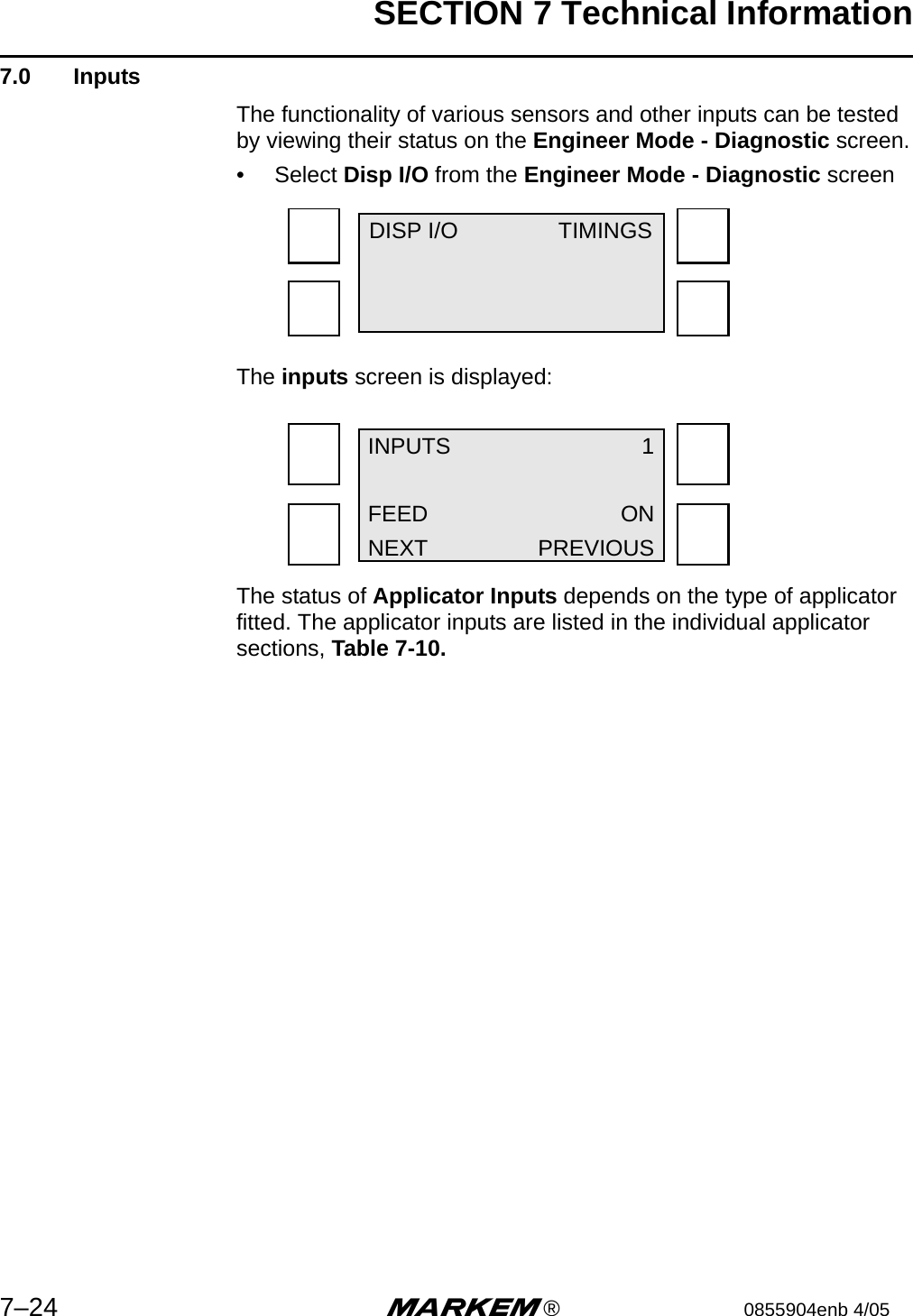
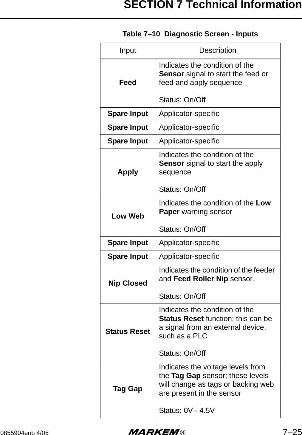
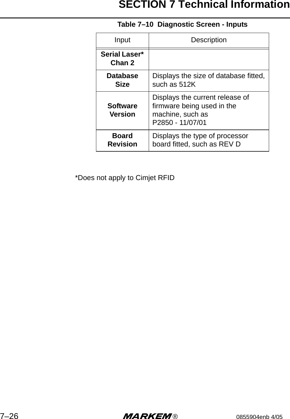
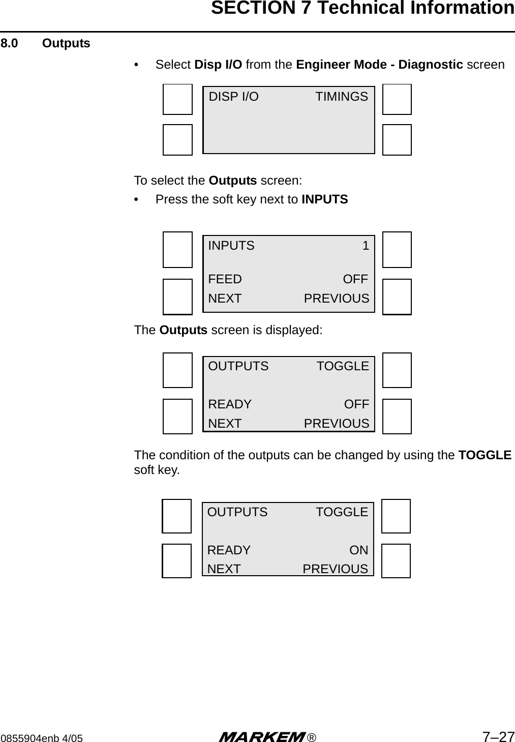
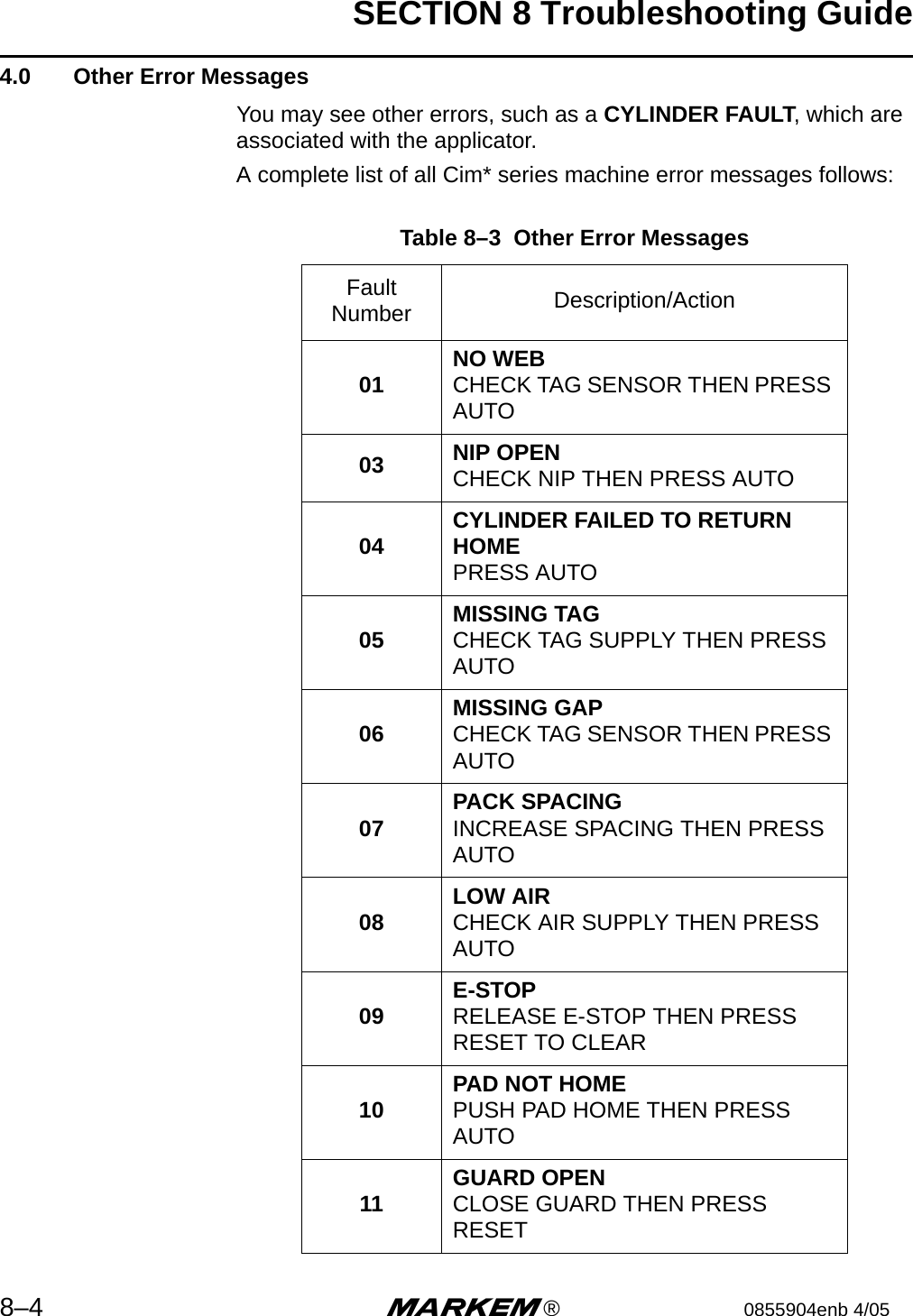
![SECTION 6 Preventive Maintenance Guide6–8 m®0855904enb 4/05 6.3 Tag Gap OpticAn optical slot sensor is used to determine if the tags are stopping in the correct position. Infrared light is passed from a transmitter to a receiver on the ends of the sensor. The tags are run through this sensor, and the amount of light passing through the tags or tag gap is recorded as a voltage change and stored as a digital figure which is used by the processor. Cimjet RFID uses stepper motors and will step these at either 8 steps/mm or 12 steps/mm. The backing web in the gap between tags will allow more light to pass through than the backing web and tags together. These voltage levels are used to determine if a tag, backing web and no tags, are present in the sensor.An example of how this process works is described below:Tag size 100mm (3.94”)Tag gap 3mm (.118”)Stepper motor 8 steps/mmWhen the Cimjet RFID feeds datum labels, the processor will record a constant voltage level for 800 (100mm [3.94”] x 8) steps of the stepper motor and then record a rise in the voltage level for 24 steps (3mm [.118”] x 8).This is used to inform the processor when to start and stop feeding.If these levels start to vary, the machine will initiate a tag feed fault.If the tag gap happens to stop in the gap sensor, this will cause tag feed problems. A second hole position for the gap sensor is provided in the base plate for this condition.Two possible optic positions are provided. The standard position is the farthest position away from the beak.If the gap optic has to be moved, the OPTIC ADJUST parameter should be set accordingly to minus 100 (-10mm)After adjustment, reset the gap optic.The gap threshold voltage is the transition voltage where the processor senses that it is transitioning from a tag to a gap or vice versa. The setting for the threshold voltage should be at the midpoint of the gap voltage and the label voltage.](https://usermanual.wiki/MARKEM/CIMJETRFID/User-Guide-570459-Page-102.png)