MARKEM CIMJETRFID Frequency Hopping RFID Tag Reader User Manual 00 Cimjet RFID Rev A EN
MARKEM Corporation Frequency Hopping RFID Tag Reader 00 Cimjet RFID Rev A EN
MARKEM >
Exhibit D Users Manual per 2 1033 b3
Cimjet
®
RFID
Operation/Service Manual
m
®
Operation/Service Manual
Cimjet® RFID

m®
WARRANTY
All MARKEM products are warranted to be free of defects in materials and workmanship and to conform to MARKEM
specifications in effect at the date of shipment to Buyer. Any changes Buyer requests to MARKEM specifications are not
effective without advance, written authorization by MARKEM. The warranty period is as follows:
Machines: One year from date of shipment to Buyer or 2000 operating hours, whichever expires first, unless any
specific machine is designated on an order or otherwise as Made to Order (“MTO”), in which event the
warranty period is 90 days from date of shipment to Buyer.
Ink Jet Orifice Plates (on new machines and as replacement parts): 90 days from date of shipment to Buyer.
Replacement Parts: 90 days from date of shipment to Buyer.
Software: 90 days from date of shipment to Buyer. Warranty does not entitle Buyer to new releases, upgrades or
enhancements introduced during the warranty period.
Supply Products: For the period of shelf life of the supplies as stated in the applicable specification standards or
one year from the date of shipment to Buyer if not specified.
During the warranty period, MARKEM will, at its option, repair, replace or refund the purchase price of MARKEM products
which prove to be defective in materials or workmanship or which do not conform to the applicable MARKEM specifications.
Within MARKEM service travel areas for certain products designated by MARKEM, warranty service for machines and parts
will be provided at the installation site. In all other cases, products must be returned to a service facility designated by
MARKEM.
For products returned to MARKEM for warranty repair or replacement, Buyer shall obtain a return authorization number and
shipping instructions from MARKEM and return the product shipping charges prepaid. Shipping charges for the return of
products to Buyer shall be paid by MARKEM within the contiguous forty-eight United States and the District of Columbia; for
all other locations, the warranty excludes all costs of shipping, customs clearance and any other related charges. All replaced
products shall become the property of MARKEM.
The foregoing warranty shall not apply to any custom work performed by MARKEM. The foregoing warranty shall also not
apply to defects or non-conformance with MARKEM specifications which result from: (l) improper installation, use, storage,
care or maintenance by Buyer; (2) wear resulting from normal use of parts subject to wear, such as ink rolls, offset pads, foil
feeds, thermal transfer print heads, etc.; (3) modification, alteration or retiming of a MARKEM machine; (4) cycling a
MARKEM machine out of specification; or (5) adding a unit timed or driven by a MARKEM machine; (6) use of products
(including supplies) or software not furnished by MARKEM (7) accident, neglect, misuse or abuse; or (8) exposure conditions
outside the range of the environmental, power and operating specifications provided by MARKEM.
NO OTHER WARRANTY IS EXPRESSED OR IMPLIED. MARKEM SPECIFICALLY DISCLAIMS ANY IMPLIED
WARRANTIES OF MERCHANTABILITY OR FITNESS FOR A PARTICULAR PURPOSE. Determination of the suitability of
the products described on the face of the quote and/or invoice is the sole responsibility of the Buyer and MARKEM shall have
no responsibility in connection therewith. BUYER WARRANTS THAT HE IS NOT PURCHASING THE PRODUCTS FOR
PERSONAL, FAMILY OR HOUSEHOLD PURPOSES. THE REMEDIES PROVIDED HEREIN ARE BUYER’S SOLE AND
EXCLUSIVE REMEDIES.
LIMITATION OF LIABILITY: MARKEM SHALL NOT BE LIABLE FOR ANY INDIRECT, SPECIAL, INCIDENTAL OR
CONSEQUENTIAL DAMAGES, WHETHER BASED IN CONTRACT, TORT OR ANY OTHER LEGAL THEORY, OR FOR
THE COST OF SUBSTITUTE GOODS. CONSEQUENTIAL DAMAGES for purposes of this Agreement shall include, without
limitation:
1. Loss of use, income or profit, or losses sustained as a result of the injury (including death) to any person or loss or
damage to property, including, without limitation, materials manufactured, processed or labeled by the use of the
products.
2. Damages arising out of or in connection with delays in delivery, MARKEM’s performance, non-performance or
breach of this contract, defects in the equipment, failure of the products to perform properly or non-conformance of
the products with specifications or the operation, use, installation, repair or replacement of the products.
0874339 Rev. 08 11/03
150 Congress Street, PO Box 2100, Keene, New Hampshire 03431-7100
TEL : 603-352-1130 FAX: 603-357-5871 http://WWW.MARKEM.com
0855904enb 4/05 m®i
This guide explains the basic operation and care of the Model Cimjet® RFID System.
To the best of our knowledge, the information contained in this guide was correct at the time
of publication. However, continual enhancement of our products can result in some
differences between the instructions represented in this guide and your printer.
MARKEM is a registered trademark of MARKEM Corporation.
This guide was written by:
MARKEM Corporation
150 Congress Street
Keene, New Hampshire 03431 U.S.A.
Copyright © 2005 by MARKEM Corporation
All rights reserved. Reproducing this publication in whole or in part without written
permission is expressly prohibited.
Reference List
The information on your packing slips can be written below for reference. When contacting
MARKEM please give your Model Number, Serial Number, and Customer Account Number.
Model ____________ Serial Number_________________ Date Installed______________
Customer Account Number__________________________________________________
Name of MARKEM Representative_____________________________________________
Options/
Accessories_______________________________________________________________
________________________________________________________________________
________________________________________________________________________
________________________________________________________________________
________________________________________________________________________
________________________________________________________________________
________________________________________________________________________
________________________________________________________________________

TABLE OF CONTENTS
0855904enb 4/05 m® iii
Section 1 General Information
1.0 Welcome to the Model Cimjet RFID . . . . . . . . . . . . . . . . . . . . . . . . . . . . 1-1
1.1 What is in this Guide? . . . . . . . . . . . . . . . . . . . . . . . . . . . . . . . . . . 1-1
1.2 Glossary . . . . . . . . . . . . . . . . . . . . . . . . . . . . . . . . . . . . . . . . . . . . 1-1
2.0 Safety Information . . . . . . . . . . . . . . . . . . . . . . . . . . . . . . . . . . . . . . . . . 1-4
2.1 Applicable Safety Regulations . . . . . . . . . . . . . . . . . . . . . . . . . . . 1-4
2.2 Modifications to Cimjet RFID . . . . . . . . . . . . . . . . . . . . . . . . . . . . 1-4
2.3 Electrical Safety . . . . . . . . . . . . . . . . . . . . . . . . . . . . . . . . . . . . . . 1-5
2.4 Machine Safety . . . . . . . . . . . . . . . . . . . . . . . . . . . . . . . . . . . . . . . 1-7
2.5 Safety Labels . . . . . . . . . . . . . . . . . . . . . . . . . . . . . . . . . . . . . . . 1-10
2.6 Isopropanol Safety . . . . . . . . . . . . . . . . . . . . . . . . . . . . . . . . . . . 1-12
2.7 Foreseen Use/misuse. . . . . . . . . . . . . . . . . . . . . . . . . . . . . . . . . 1-22
2.8 MARKEM Training Programs . . . . . . . . . . . . . . . . . . . . . . . . . . . 1-22
2.9 Removal from Service. . . . . . . . . . . . . . . . . . . . . . . . . . . . . . . . . 1-23
3.0 Overview . . . . . . . . . . . . . . . . . . . . . . . . . . . . . . . . . . . . . . . . . . . . . . . 1-24
3.1 Components of Cimjet RFID . . . . . . . . . . . . . . . . . . . . . . . . . . . . 1-26
3.1.1 Dispenser. . . . . . . . . . . . . . . . . . . . . . . . . . . . . . . . . . . . . 1-26
3.1.2 Applicator . . . . . . . . . . . . . . . . . . . . . . . . . . . . . . . . . . . . . 1-26
3.2 Tag Sizes . . . . . . . . . . . . . . . . . . . . . . . . . . . . . . . . . . . . . . . . . . 1-26
3.3 Beacon Light (Optional) . . . . . . . . . . . . . . . . . . . . . . . . . . . . . . . 1-29
3.4 Networking . . . . . . . . . . . . . . . . . . . . . . . . . . . . . . . . . . . . . . . . . 1-29
4.0 Dimensional Drawings (in Millimeters) . . . . . . . . . . . . . . . . . . . . . . . . 1-30
Section 2 Installation Guide
1.0 Installation of the Cimjet RFID . . . . . . . . . . . . . . . . . . . . . . . . . . . . . . . . 2-1
1.1 Installation Requirements . . . . . . . . . . . . . . . . . . . . . . . . . . . . . . . 2-1
2.0 Power . . . . . . . . . . . . . . . . . . . . . . . . . . . . . . . . . . . . . . . . . . . . . . . . . . 2-2
2.1 Power Configuration . . . . . . . . . . . . . . . . . . . . . . . . . . . . . . . . . . . 2-2
3.0 Air Requirements . . . . . . . . . . . . . . . . . . . . . . . . . . . . . . . . . . . . . . . . . . 2-3
3.1 Air Regulator . . . . . . . . . . . . . . . . . . . . . . . . . . . . . . . . . . . . . . . . . 2-3
4.0 I/O Interface . . . . . . . . . . . . . . . . . . . . . . . . . . . . . . . . . . . . . . . . . . . . . . 2-4
5.0 Positioning the Applicator . . . . . . . . . . . . . . . . . . . . . . . . . . . . . . . . . . . 2-4

TABLE OF CONTENTS
iv m® 0855904enb 4/05
Section 3 Operating Guide
1.0 Preparing Cimjet RFID for Operation . . . . . . . . . . . . . . . . . . . . . . . . . . .3-1
2.0 Operating the Cimjet RFID . . . . . . . . . . . . . . . . . . . . . . . . . . . . . . . . . . .3-1
3.0 Loading Tags . . . . . . . . . . . . . . . . . . . . . . . . . . . . . . . . . . . . . . . . . . . . .3-1
4.0 Power-up . . . . . . . . . . . . . . . . . . . . . . . . . . . . . . . . . . . . . . . . . . . . . . . . .3-3
5.0 Operator Interface . . . . . . . . . . . . . . . . . . . . . . . . . . . . . . . . . . . . . . . . . .3-4
5.1 Menu Operation . . . . . . . . . . . . . . . . . . . . . . . . . . . . . . . . . . . . . . .3-4
5.2 The Control Panel . . . . . . . . . . . . . . . . . . . . . . . . . . . . . . . . . . . . .3-4
5.3 Operator Interface LEDs . . . . . . . . . . . . . . . . . . . . . . . . . . . . . . . .3-5
5.4 Guidelines for Entering Data . . . . . . . . . . . . . . . . . . . . . . . . . . . . .3-5
6.0 Auto and Set Mode . . . . . . . . . . . . . . . . . . . . . . . . . . . . . . . . . . . . . . . . .3-6
6.1 Auto Mode . . . . . . . . . . . . . . . . . . . . . . . . . . . . . . . . . . . . . . . . . . .3-7
6.2 Set Mode . . . . . . . . . . . . . . . . . . . . . . . . . . . . . . . . . . . . . . . . . . . .3-8
7.0 Engineer Mode . . . . . . . . . . . . . . . . . . . . . . . . . . . . . . . . . . . . . . . . . . .3-10
7.1 Diagnostics. . . . . . . . . . . . . . . . . . . . . . . . . . . . . . . . . . . . . . . . . .3-10
7.2 Set Tag Optic . . . . . . . . . . . . . . . . . . . . . . . . . . . . . . . . . . . . . . . .3-10
8.0 Parameters . . . . . . . . . . . . . . . . . . . . . . . . . . . . . . . . . . . . . . . . . . . . . .3-11
Section 4 Restricted Access Mode User Guide
1.0 Restricted Access Mode User Guide . . . . . . . . . . . . . . . . . . . . . . . . . . .4-1
2.0 Entering Restricted Access Mode . . . . . . . . . . . . . . . . . . . . . . . . . . . . . .4-1
3.0 Machine Init (Initialization) . . . . . . . . . . . . . . . . . . . . . . . . . . . . . . . . . . .4-2
3.1 Reset Params. . . . . . . . . . . . . . . . . . . . . . . . . . . . . . . . . . . . . . . . .4-2
4.0 Password . . . . . . . . . . . . . . . . . . . . . . . . . . . . . . . . . . . . . . . . . . . . . . . .4-3
4.1 Password Configuration . . . . . . . . . . . . . . . . . . . . . . . . . . . . . . . . .4-4
4.2 Password Key Sequences . . . . . . . . . . . . . . . . . . . . . . . . . . . . . . 4-6
5.0 Cycle . . . . . . . . . . . . . . . . . . . . . . . . . . . . . . . . . . . . . . . . . . . . . . . . . . . .4-7
6.0 Restricted Setup . . . . . . . . . . . . . . . . . . . . . . . . . . . . . . . . . . . . . . . . . . .4-8
7.0 Set Parameters . . . . . . . . . . . . . . . . . . . . . . . . . . . . . . . . . . . . . . . . . . . .4-8
8.0 Communications Parameters . . . . . . . . . . . . . . . . . . . . . . . . . . . . . . . . .4-9
9.0 Machine Options Parameters . . . . . . . . . . . . . . . . . . . . . . . . . . . . . . . .4-11
9.1 Machine Configuration Parameters . . . . . . . . . . . . . . . . . . . . . . .4-12
9.2 Applicator Parameters . . . . . . . . . . . . . . . . . . . . . . . . . . . . . . . . .4-16
10.0 Feeder Parameters . . . . . . . . . . . . . . . . . . . . . . . . . . . . . . . . . . . . . . . .4-17
Section 5 Operating Modes
1.0 Operating Modes . . . . . . . . . . . . . . . . . . . . . . . . . . . . . . . . . . . . . . . . . .5-1
2.0 Application Cycle . . . . . . . . . . . . . . . . . . . . . . . . . . . . . . . . . . . . . . . . . .5-1
2.1 Auto Apply Mode . . . . . . . . . . . . . . . . . . . . . . . . . . . . . . . . . . . . . .5-2
2.2 On Demand Mode . . . . . . . . . . . . . . . . . . . . . . . . . . . . . . . . . . . . .5-2
3.0 Connecting External Sensors . . . . . . . . . . . . . . . . . . . . . . . . . . . . . . . . .5-3
3.1 Wiring the Sensors . . . . . . . . . . . . . . . . . . . . . . . . . . . . . . . . . . . . .5-3
3.2 Testing the Sensors . . . . . . . . . . . . . . . . . . . . . . . . . . . . . . . . . . . .5-3
4.0 Positioning Sensors . . . . . . . . . . . . . . . . . . . . . . . . . . . . . . . . . . . . . . . .5-4

TABLE OF CONTENTS
0855904enb 4/05 m® v
4.1 Auto Apply Sensor Position . . . . . . . . . . . . . . . . . . . . . . . . . . . . . 5-4
4.2 On Demand Mode Sensor Position . . . . . . . . . . . . . . . . . . . . . . . 5-5
5.0 Fitting the Sensors . . . . . . . . . . . . . . . . . . . . . . . . . . . . . . . . . . . . . . . . . 5-6
6.0 Apply Delay . . . . . . . . . . . . . . . . . . . . . . . . . . . . . . . . . . . . . . . . . . . . . . 5-6
Section 6 Preventive Maintenance Guide
1.0 General Maintenance and Cleaning . . . . . . . . . . . . . . . . . . . . . . . . . . . 6-1
1.1 General Information . . . . . . . . . . . . . . . . . . . . . . . . . . . . . . . . . . . 6-1
1.2 Positioning of Safety Labels . . . . . . . . . . . . . . . . . . . . . . . . . . . . . 6-1
2.0 Cleaning of all Rollers . . . . . . . . . . . . . . . . . . . . . . . . . . . . . . . . . . . . . . 6-2
3.0 Changing the Tag Size . . . . . . . . . . . . . . . . . . . . . . . . . . . . . . . . . . . . . 6-3
4.0 Tag Unwind Brake . . . . . . . . . . . . . . . . . . . . . . . . . . . . . . . . . . . . . . . . . 6-4
5.0 Clutches . . . . . . . . . . . . . . . . . . . . . . . . . . . . . . . . . . . . . . . . . . . . . . . . . 6-5
5.1 Replacing the Felt Pads . . . . . . . . . . . . . . . . . . . . . . . . . . . . . . . . 6-5
5.2 Setting the Clutch Torque . . . . . . . . . . . . . . . . . . . . . . . . . . . . . . . 6-6
6.0 Sensor Adjustment . . . . . . . . . . . . . . . . . . . . . . . . . . . . . . . . . . . . . . . . 6-7
6.1 Low Reel Sensor. . . . . . . . . . . . . . . . . . . . . . . . . . . . . . . . . . . . . . 6-7
6.2 Nip Home Sensor . . . . . . . . . . . . . . . . . . . . . . . . . . . . . . . . . . . . . 6-7
6.3 Tag Gap Optic. . . . . . . . . . . . . . . . . . . . . . . . . . . . . . . . . . . . . . . . 6-8
7.0 Drive Belts . . . . . . . . . . . . . . . . . . . . . . . . . . . . . . . . . . . . . . . . . . . . . . 6-10
8.0 Maintaining the Compressed Air . . . . . . . . . . . . . . . . . . . . . . . . . . . . . 6-12
Section 7 Technical Information
1.0 Power Configuration . . . . . . . . . . . . . . . . . . . . . . . . . . . . . . . . . . . . . . . 7-1
1.1 Power Connector . . . . . . . . . . . . . . . . . . . . . . . . . . . . . . . . . . . . . 7-1
1.2 Power Connections. . . . . . . . . . . . . . . . . . . . . . . . . . . . . . . . . . . . 7-2
2.0 The Cimjet RFID Main Processor Board . . . . . . . . . . . . . . . . . . . . . . . . 7-3
2.1 On-board Connectors . . . . . . . . . . . . . . . . . . . . . . . . . . . . . . . . . . 7-4
2.2 Input and Output LEDs . . . . . . . . . . . . . . . . . . . . . . . . . . . . . . . . . 7-7
2.3 Processor Board Links . . . . . . . . . . . . . . . . . . . . . . . . . . . . . . . . . 7-9
2.4 Test Points . . . . . . . . . . . . . . . . . . . . . . . . . . . . . . . . . . . . . . . . . 7-11
2.5 Fuses . . . . . . . . . . . . . . . . . . . . . . . . . . . . . . . . . . . . . . . . . . . . . 7-13
2.6 Firmware and RAM . . . . . . . . . . . . . . . . . . . . . . . . . . . . . . . . . . . 7-14
2.7 Switch Settings and Potentiometers . . . . . . . . . . . . . . . . . . . . . . 7-15
3.0 External Connectors . . . . . . . . . . . . . . . . . . . . . . . . . . . . . . . . . . . . . . 7-16
3.1 X28 Communications (Comms) . . . . . . . . . . . . . . . . . . . . . . . . . 7-17
3.2 X23 External Sensor Connection . . . . . . . . . . . . . . . . . . . . . . . . 7-18
3.3 X12 External I/O . . . . . . . . . . . . . . . . . . . . . . . . . . . . . . . . . . . . . 7-19
4.0 Status Output . . . . . . . . . . . . . . . . . . . . . . . . . . . . . . . . . . . . . . . . . . . . 7-21
5.0 Status Reset Input . . . . . . . . . . . . . . . . . . . . . . . . . . . . . . . . . . . . . . . . 7-22
6.0 Display I/O . . . . . . . . . . . . . . . . . . . . . . . . . . . . . . . . . . . . . . . . . . . . . . 7-23
7.0 Inputs . . . . . . . . . . . . . . . . . . . . . . . . . . . . . . . . . . . . . . . . . . . . . . . . . . 7-24
8.0 Outputs . . . . . . . . . . . . . . . . . . . . . . . . . . . . . . . . . . . . . . . . . . . . . . . . 7-27
9.0 Pneumatics . . . . . . . . . . . . . . . . . . . . . . . . . . . . . . . . . . . . . . . . . . . . . 7-29

TABLE OF CONTENTS
vi m® 0855904enb 4/05
9.1 Air Requirements . . . . . . . . . . . . . . . . . . . . . . . . . . . . . . . . . . . . .7-29
9.2 Compressed Air Requirements . . . . . . . . . . . . . . . . . . . . . . . . . .7-29
Section 8 Troubleshooting Guide
1.0 Error Messages in Auto Mode . . . . . . . . . . . . . . . . . . . . . . . . . . . . . . . .8-1
2.0 Power-up Error Messages . . . . . . . . . . . . . . . . . . . . . . . . . . . . . . . . . . .8-2
3.0 Start-up Error Messages . . . . . . . . . . . . . . . . . . . . . . . . . . . . . . . . . . . . .8-3
4.0 Other Error Messages . . . . . . . . . . . . . . . . . . . . . . . . . . . . . . . . . . . . . . .8-4
5.0 Communications Problems . . . . . . . . . . . . . . . . . . . . . . . . . . . . . . . . . . .8-7
6.0 Tag Feed Problems . . . . . . . . . . . . . . . . . . . . . . . . . . . . . . . . . . . . . . . .8-8
6.1 Incorrect Tag Stopping Position . . . . . . . . . . . . . . . . . . . . . . . . . . .8-8
6.2 Erratic Tag Feeding . . . . . . . . . . . . . . . . . . . . . . . . . . . . . . . . . . . .8-8
6.3 Inconsistent Tag Stopping Position . . . . . . . . . . . . . . . . . . . . . . . .8-9
6.3.1 If the Tag Stops in the Correct Position . . . . . . . . . . . . . . .8-9
6.3.2 If the Tag Stops in an Inconsistent Position . . . . . . . . . . . .8-9
7.0 No Driving of Tags . . . . . . . . . . . . . . . . . . . . . . . . . . . . . . . . . . . . . . . .8-10
8.0 Motor Stalling . . . . . . . . . . . . . . . . . . . . . . . . . . . . . . . . . . . . . . . . . . . .8-10
Section 9 Recommended Spares
1.0 Recommended Spares . . . . . . . . . . . . . . . . . . . . . . . . . . . . . . . . . . . . . .9-1
1.1 Preventive Maintenance Spares Kits . . . . . . . . . . . . . . . . . . . . . . .9-1
1.2 General Spares Kits . . . . . . . . . . . . . . . . . . . . . . . . . . . . . . . . . . . .9-2
1.3 Left-hand Change Parts . . . . . . . . . . . . . . . . . . . . . . . . . . . . . . . . .9-2
Section 10 Parts Illustrations and Electrical Schematics

Cimjet ® RFID
Operation/Service Manual
m
®
SECTION 1
General Information

SECTION 1 General Information
0855904enb 4/05 m®1–1
1.0 Welcome to the Model Cimjet RFID
The Cimjet RFID is a high speed, compact RFID tag dispenser and
applicator that is compatible with a full range of MARKEM products.
1.1 What is in this Guide?
The Cimjet RFID manual addresses the basic installation, operation
and care of the RFID tag dispenser, as well as safety, maintenance,
troubleshooting, and service information. For more applicator
information, refer to the Cimjet RFID Blow Applicator Manual
(0855906) and the Cimjet RFID Tamp Applicator Manual
(0855907).
1.2 Glossary
active tags – tags that use batteries as a source of power (can be
either partial or complete power); there are tags with replaceable
batteries and tags that have the batteries inside a sealed unit –
sometimes called unitized active tags
addressability – ability to address bits, fields, files or other portions
of storage in a tag
antenna – conductive elements that radiate and/or receive energy
in the radio frequency spectrum to or from the tag
bi-directional – a tag that can be read or written from either side
capacity – amount of bits or bytes that can be programmed into a
tag; these may be bits accessible to the user, or the total number,
including those reserved for the manufacturer (such as parity or
control bits)
electronic tag – a tag that has an electronic RFID tag embedded
within it
EMC – electromagnetic compatibility
frequency – number of times a signal makes a complete pass
through its maximum and minimum values and returns to the same
value (cycles)
misread – a condition that exists when the data presented by the
reader does not match the corresponding data in the tag
passive tags – tags that do not contain an internal power source;
they are externally powered and usually get their power from the
carrier signal radiated from the scanner
programming – adding information to or altering a tag
programmability – data and identification information must be
entered into tags in order for them to become identifiers of specific
objects; this capability is called programmability

SECTION 1 General Information
1–2 m®0855804enb 4/05
programmer – tag contents can be changed by a set of electronics
in close proximity or in electrical contact with them; those electronics
and their packaging are called a programmer
RFID – systems that read or write data to RF (radio frequency) tags
that are present in a radio frequency field projected from RF
reading/writing equipment; data may be contained in one or more
bits for the purpose of providing identification and other information
relevant to the object the tag is attached to; it uses electromagnetic
or electrostatic coupling in the radio frequency portion of the
spectrum to communicate to or from a tag through a variety of
modulation and encodation schemes
range – distance at which successful reading and/or writing can be
attained
read – decoding, extraction and presentation of data from
formatting, control and error management bits sent from a tag
readability – ability to extract data under less than optimal
conditions
read rate – maximum rate at which data can be read from a tag,
expressed in bits or bytes per second
read/write – many applications require that new data, or revisions to
data already in the tag, be entered into the tag while it is still
attached to its object; tags with this capability are said to be
reprogrammable and are called read/write tags, memory cards, or
memory modules
reader – device containing the digital electronics that extract and
separate the information from the format definition and error
management bits; digital electronics perform the actual reading
function; these read electronics may also interface to an integral
display and/or provide a parallel or serial communications interface
to a host computer or industrial controller
reader/writer – the set of electronics can change the contents of the
tags while they are still attached to their object; they are called the
reader/writer (see reader)
reprogrammable – many applications require that new data, or
revisions to data already in the tag, be entered into the tag while it is
still attached to its object; the ability to read from and write data to
the tag while it is attached to its object is called in-use
programming; tags with this capability are said to be
reprogrammable and are called read/write tags, memory cards, or
memory modules

SECTION 1 General Information
0855904enb 4/05 m®1–3
scanner – the antennae, transmitter (or exciter) and receiver
electronics are integrated in a single package called the scanner;
they may be combined with additional digital electronics, including a
microprocessor in a package called a reader
tag – the transmitter/receiver pair, or the transceiver plus the
information storage mechanism, attached to the object, is referred to
as the tag, transponder, electronic tag, code plate, and various other
terms. Although transponder is technically the most accurate, the
most common term and the one preferred by the Automatic
Identification manufacturers is tag
transponder – see tag
verify – assure that the desired operation was performed correctly
write – transfer of data to a tag; the tag’s internal operation of
storing the data, sometimes including the data, in order to verify the
operation
write rate – rate at which information is transferred to a tag, written
into the tag’s memory and verified as being correct; it is quantified
as the average number of bits or bytes per second in which the
complete transaction can be performed

SECTION 1 General Information
1–4 m®0855804enb 4/05
2.0 Safety Information
2.1 EMC (Electromagnetic Compatibility) Considerations
To maintain the integrity of the EMC precautions taken with the
Cimjet RFID, all connecting cables must be fully screened, and the
screen must have 360 degree contact with the metal connector and,
in turn, the unit’s case at both ends.
2.2 Modifications to Cimjet RFID
Any changes or modifications not expressly approved by MARKEM
that could affect FCC Compliance could void the user’s authority to
operate the Cimjet RFID.

SECTION 1 General Information
0855904enb 4/05 m®1–5
2.3 Electrical Safety
• Incoming supply cable should be rated at 10A minimum for the
Cimjet RFID (independent of nominal supply voltage)
Maximum switch-on supply current surge for the Cimjet RFID is as
follows: Cimjet RFID Maximum current level = 70A,
Duration = 6ms
Recommended cable protection is as follows:
• MCB (Miniature Circuit Breaker): to IEC 947-2 / EN 60947-2 and
BS EN 60898 with a minimum instantaneous release response
current of 10x rated current (type D)
• Klockner Moeller type FAZNS 6-2 (6A, 2 pole type D)
• Merlin Gerin type C60 HD 206 (6A, 2 pole type D)
Note: The Klockner Moeller or Merlin Gerin circuit breakers are
recommended. An equivalent MCB can be used.

SECTION 1 General Information
1–6 m®0855804enb 4/05
Fuses
• Use 10A HRC or HBC type fuses with a minimum of 95A RMS
symmetrical prospective current rating, at a 10ms minimum pre-
arcing time, such as ASTA certified to BS88 part 2 ‘pullcap’ type
or equivalent.
Electrical safety testing (after installation)
WARNING: It is essential that the continuity of the protective
bonding circuit and the prospective short circuit
current level be checked after the machine is
installed and the electrical connections, including
those to the power supply, are complete. A
competent person must carry out these tests.
Test equipment required: Digital Loop and PSC Tester (such as
Robin Model KMP4120 Digital PSC-LOOP Tester)
• Connect tester to incoming mains supply to machine.
• Check that the supply voltage is within specification and that the
connections are correctly wired (indicated on the tester).
• Select the 20 ohms scale on the tester and press the Test
button to check the value of earth fault loop impedance for the
power supply provided.
If a class D MCB to BS EN 60898 or equivalent protects the supply,
then the maximum impedance should be 2 ohms.
If the supply is protected by a BS88 part 2 style fuse, then the
maximum impedance should be 5.33 ohms.
Select the PSC (Prospective Short Circuit Current) test and check that
the PSC level does not exceed 1500A.
WARNING: Failure to carry out these tests will potentially
result in an unsafe installation, and the equipment
fault-clearance ability may not function correctly.

SECTION 1 General Information
0855904enb 4/05 m®1–7
2.4 Machine Safety
The product is designed to conform to all current Machine Safety
Regulations. Please read through this section before operating
this machine.
This feeder is designed for use with the following supply systems
that conform to IEC 664 light industrial / domestic installation
category II main supply.
• ‘TN’ (any of following - TN-C, TN-S or TN-C-S) For example: a
system having one or more points of the source of energy
directly earthed; the exposed conductive parts of the installation
being connected to that point by protective conductors
• ‘TT’ - For example: a system having one point of the source of
energy directly earthed; the exposed conductive parts of the
installation being connected to earth electrodes electrically
independent of the earth electrodes of the source
• It is NOT suitable for connection to an ‘IT’ system. For example:
a system having no direct connection between live parts and
earth, the exposed conductive parts of the installation being
earthed; this, therefore, excludes any ‘phase to phase’
connected supplies such as what might be available in some
factories and/or countries
If either supply fuse (located on the rear of the controller, below the
supply connector) is replaced, it must be replaced by an HBC Style
ceramic fuse with the rating shown as ‘T5AH250V.’
WARNING: Installation must only be performed by qualified
MARKEM personnel. For customer installations,
authorization must be obtained from MARKEM. All
relevant Safety Procedures must be followed.
Failure to do so may void the warranty.
1. The Cimjet RFID must be disconnected from the main power
supply before removing the cover from the I/O interface board.
Make sure that any external interlocked machines are also
disconnected from the power supply.
2. DO NOT touch restrictors/regulators that are mounted inside the
rear dispenser cover. These are pre-set at the factory for your
safety.
3. ALWAYS disconnect the power to the machine before removing
any covers. You must remove the plug from the main power
supply.
4. DO NOT operate the machine with any covers removed. All
covers must be in place using the appropriate number of
fasteners. It is essential that electrical and non-electrical

SECTION 1 General Information
1–8 m®0855804enb 4/05
connector dust covers provided with the machine are fitted to all
unused connectors to protect against dust and dirt and prevent
possible static damage to internal components.
5. DISCONNECT the air supply before undertaking work on the
applicator.
6. DO NOT adjust the internal cylinder regulator pressure under
any circumstances. Doing so could make the Cimjet RFID
unsafe.
7. It is possible for the machine to become unstable when being
moved. The machine must be lowered to its lowest possible
position before moving, and care must taken to prevent personal
injury.
8. Loading tags can present a risk if the machine is mounted high
up as the tag reels are heavy. It may be necessary to provide a
platform on which to stand, enabling the operator to load tag
reels safely, without risk of personal injury. When lowering the
machine, be sure a minimum of two people reposition or move
the machine and that it is fully supported.
9. Always take care when moving around the machine not to slip,
trip, or fall, especially when the machine is used in areas where
the floor may be wet or greasy.
10.Be aware of the operating zone required by the Cimjet RFID
when working with and near the machine. Allow ample space
beyond the applicator operation zone to ensure operator safety.
Be certain all reasonable safety precautions have been
undertaken; however, when working with or around the machine,
take care to avoid potential hazards. If the customer has any
safety concerns, guarding must be provided by the customer.
11. Be aware that free items, such as loose clothing or long hair,
could become entangled or trapped in the Tag Nip Roller or
paper path during the operation of the machine. A warning
sticker is fitted locally to highlight the hazard.
12.Beware of the unlikely event of an electronic fault causing an
unexpected start-up or overrun of the pneumatic cylinders or
feeder drive motors, which could cause possible injury.
13.The regulator mounted inside the rear dispenser cover is set to
1.86 Bar for safety reasons and should only be serviced or
replaced by trained personnel. If the cylinder pressure is raised
above 1.86 Bar, the customer must provide additional guarding
for operator safety.
14.Make sure that the maximum light emission power and
classification for any/all laser(s) used on this machine, do not

SECTION 1 General Information
0855904enb 4/05 m®1–9
exceed those specifications stated in the appropriate laser safety
standards IEC825. When irregularities are detected in the laser
beam generation, internal protective devices must switch the
laser beam off.
15.Various safety and warning labels are placed on the Cimjet RFID
(see following pages).
WARNING: These labels are provided for your safety and
should not be ignored or removed.
16.All fixing screws in all covers must be used to ensure EMC
integrity.
SECTION 1 General Information
1–10 m®0855804enb 4/05
2.5 Safety Labels
The safety information in this manual is correct to the best of our
knowledge, information, and belief at the date of this publication.
The information given is designed only as guidance for safe
handling use, processing, storage, transportation, disposal and
release and is not considered a warranty or quality specification.
The information relates only to the specific material designated and
may not be valid for such material used in combination with any
other materials or in any process unless specified in text.
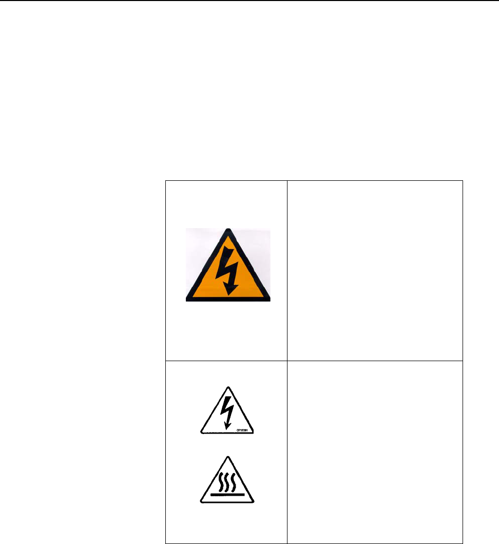
Table 1–1 Safety Labels
Line Voltage
Part Number
BO5263AA
There is a danger of electrical
shock during checks and
repair.
Remove the power cord from
the electrical outlet before
performing all checks and
repair.
All electronic checks must be
performed by a qualified
technician.
Hot Surfaces
Part Number
BO5265AA
To prevent mild injury from
burns, be careful not to
directly touch any surface
where this safety sticker is
placed.
SECTION 1 General Information
0855904enb 4/05 m®1–11
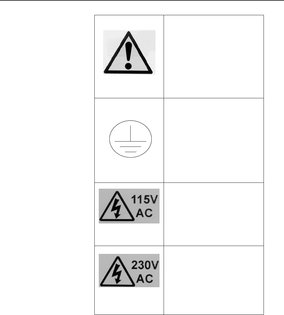
Hazard Warning
Part Number
BO5262AA
Hazard warning safety labels
are placed in strategic
positions around the machine
to highlight potential hazards
to the operator.
Earth
Part Number
BO5264AA
Earth labels are placed in
strategic positions around the
machine to highlight the
machines earthing point.
Part Number
34976BA
Use only 115V connections
where you find this safety
label.
Part Number
34977BA
Use only 230V connections
where you find this safety
label.
Table 1–1 Safety Labels

SECTION 1 General Information
1–12 m®0855804enb 4/05
2.6 Isopropanol Safety
Table 1–2 Isopropanol Safety
Product Name Isopropanol Wipes
Part Number BO4985AA
Product Name Isopropanol Cleaning Kit
Part Number BO3285AA
Product Name Isopropanol Top Up Kit
Part Number BO3286AA
Supplier MARKEM Technologies Ltd.
Alexander Fleming Building,
Nottingham Science and
Technology Park, University
Boulevard,
Nottingham,
NG7 2RF
Composition/Information on Ingredients
Identification of the
preparation
Chemical Name
CAS-No EEC No
Class Weight%
Isopropanol Wipes Cloth
impregnated with 2ml fluid
~PROPAN-2-OL 67-63-0 200-
746-9 F:R11<90 Sweden:
V:R30 / 322, R313 Non
Hazardous Constituents>10
Isopropanol Kits
Alcohol ~PROPAN-2-OL 67-
63-0 200-661-7

SECTION 1 General Information
0855904enb 4/05 m®1–13
Hazards Identification
Isopropanol Wipes
Most Important
Hazards
Highly Flammable
Isopropanol Kits
Most Important
Hazards
Highly Flammable
Specific Hazards May cause slight eye / skin
irritation. May cause irritation
of respiratory tract. High
concentration of vapors may
induce unconsciousness /
narcosis. Solvents may
degrease the skin.
First Aid Measures
General Advice Use in well ventilated areas
Inhalation Take patient to fresh air. Do
not move about. Obtain
medical advice.
Skin Contact Remove spillage with soft
tissue and / or wash off skin
with cool water. Obtain
medical advice in extreme
cases.
Eye Contact Irrigate thoroughly with water
for at least 10 minutes. Obtain
medical advice.
Ingestion
Isopropanol Wipes Wash out mouth thoroughly
and obtain medical advice.
Isopropanol
Cleaning Kit /
Isopropanol Top Up
Kit
Drink water and obtain
medical advice.
Table 1–2 Isopropanol Safety

SECTION 1 General Information
1–14 m®0855804enb 4/05
Fire Fighting Measures
Isopropanol Wipes Carbon Dioxide, Dry Chemical
Foam / Water Spray
Isopropanol
Cleaning Kit Water Spray, Dry Powder or
Vaporizing Liquids
Isopropanol Top Up
Kit Carbon Dioxide, Dry Chemical
Foam / Water Spray
Accidental Release
Personal
Precautions Remove all sources of ignition.
Wear suitable gloves and eye/
face protection.
Environmental
Precautions Clean with water and dispose
of water and isopropanol
according to your local
environmental regulations.
Otherwise, absorb on an inert
absorbent (sand, silica gel,
acid binder, universal binder,
sawdust) transfer to container
and arrange removal by
disposal company. Ventilate
area to dispel residual vapor.
Handling and Storage
Handling Use only in well ventilated
areas. Do not breathe vapors
or spray mist. Avoid contact
with the skin and the eyes.
When using isopropanol, do
not eat, drink or smoke.
Storage Keep in a cool, well ventilated
place. Keep product and
empty container away from
heat and sources of ignition.
Take precautionary
measures against static
discharges.
Table 1–2 Isopropanol Safety

SECTION 1 General Information
0855904enb 4/05 m®1–15
Exposure Control/Personal Protection
Personal Protection
Equipment Respiratory protection;
adequate ventilation
Hand Protection Solvent resistant gloves
Eye Protection Safety glasses/face shield
Skin and Body
Protection Plastic apron/sleeves/boots
(dependent on amount
handled)
Physical and Chemical Properties
Isopropanol Wipes
Form Of Liquid
Color Colorless
Odor Characteristic
Melting
Temperature -89oC
Boiling Temperature 82oC
Density (g/ml) 0.78
Vapor Pressure 33 mmHg, 20oC
(Density) (2.07)
Solubility in Water Miscible in all proportions
Flash Point 12oC
Explosion Limits Lower: 2.3%, Upper: 12%
Auto Ignition
Temperature 425oC
Table 1–2 Isopropanol Safety

SECTION 1 General Information
1–16 m®0855804enb 4/05
Isopropanol Kits
Form Liquid
Color Colorless
Odor Characteristic
Melting
Temperature -89oC
Boiling Temperature 82oC
Density (g/ml) 0.78
Vapor Pressure 33 mmHg, 20oC
(Density) (2.07)
Solubility in Water Miscible in all proportions
Flash Point 12oC
Explosion Limits Lower: 2.3%, Upper: 12%
Auto Ignition
Temperature 425oC
Table 1–2 Isopropanol Safety

SECTION 1 General Information
0855904enb 4/05 m®1–17
Stability and Reactivity
Stability Stable; vapors may form
explosive mixture with air
Conditions to Avoid Keep away from heat and
sources of ignition
Materials to Avoid Oxidizing agents, strong
bases, aldehydes, ammonia,
chlorinated compounds,
amines, organic nitro
compounds, aluminium
Hazardous
Decomposition
Products
Peroxides
Table 1–2 Isopropanol Safety

SECTION 1 General Information
1–18 m®0855804enb 4/05
Toxicological Information
Isopropanol Wipes
Acute Toxicity IPA: LD50/oral/rat= 5.04 g/kg
LD50/dermal/rabbit = 16.4 ml/
kg
Local Effects May cause skin irritation in
susceptible persons
Sensitization May cause sensitization by
skin contact
Long-term Toxicity Liver injury may occur
Chronic Toxicity Effects of excessive
exposures may include liver
toxicity
Isopropanol Kits
After Inhalation Irritation symptoms in the
respiratory tract
After Absorption Headache, dizziness,
inebriation, unconsciousness,
narcosis
After Uptake of
Large Quantities Respiratory paralysis, coma
After Skin Contact Irritation
After Eye Contact Irritation
Further Data LD50 5045 mg/kg oral, rat. No
evidence of carcinogenic
properties; evidence of
reproductive effects
Table 1–2 Isopropanol Safety

SECTION 1 General Information
0855904enb 4/05 m®1–19
Ecological Information
Isopropanol Wipes Not readily biodegradable
IPA LC50/96h fathead minnows =
9600mg/1
Isopropanol Kits No environmental hazard
provided that the material is
handled and disposed of with
due care and attention
Disposal Considerations
Waste from
Residues/Unused
Products
Dispose of as special waste in
compliance with local
regulations
Regulations 1980,
Contaminated
Packaging
Store containers and offer for
recycling of material according
to local regulations
Table 1–2 Isopropanol Safety

SECTION 1 General Information
1–20 m®0855804enb 4/05
Transport Information
Isopropanol Wipes
UN-No 1219
Item 3o(b)
HI/UN No 1219
Proper Shipping
Name Isopropanol
IMO Class 3.2
IMDG Page 3244
EmS 3-06
MFAG 305
Proper Shipping
Name Isopropanol
ICAO Class 3
UN/ID No 1219
Proper Shipping
Name Isopropanol
Isopropanol Kits
UN-No 1219
IMDG Class II
IMO 3.2/1219
Packaging Group II
TATA 1219
Packaging Group II
Correct Technical
Name Isopropanol (Isopropyl
Alcohol)
ADR/RID 3, 3o(b)
Table 1–2 Isopropanol Safety

SECTION 1 General Information
0855904enb 4/05 m®1–21
Regulatory Information
Labeling According
to EEC Directives 90/492/EEC
Symbol F Highly Flammable
R Phrase (s) R11 Highly Flammable
S Phrase (s) S2, Keep out of reach of
children. Keep container
tightly closed in a cool, well
ventilated place.
S7-16, Keep away from
sources of ignition - NO
SMOKING.
S33, Take precautionary
measures against static
discharges.
Table 1–2 Isopropanol Safety

SECTION 1 General Information
1–22 m®0855804enb 4/05
2.7 Foreseen Use/Misuse
This manual provides information about Safety, Installation,
Operation, Troubleshooting, Illustrated Parts, Electrical Schematics,
Recommended Spares and Preventive Maintenance Procedures.
Using the Cimjet RFID in any other manner is considered a misuse
of the product. Please consult your local MARKEM Business Center
before using this Cimjet RFID for anything other than the foreseen
use.
Misuses include, but are not limited to:
• Operating a system that is incomplete, cannot be serviced, or
has been modified without authorization
• Failing to observe hazard requirements in the manual and/or on
safety labels
• Combining or interfacing non-MARKEM equipment with this
system, other than as intended
• Permitting a person who has not been fully trained to operate
and/or service the system
• Using unspecified supplies or material which may produce
unsatisfactory or unexpected results
2.8 MARKEM Training Programs
Operators, maintenance personnel, and service technicians are
considered “qualified” when they have gained, through training and
experience, an understanding of safe and correct methods of
operation, maintenance, or repair.
MARKEM conducts training programs. In addition to ongoing
courses about current machine models, customers are invited to
inquire about any training need.

SECTION 1 General Information
0855904enb 4/05 m®1–23
2.9 Removal from Service
Follow these instructions to remove the Cimjet RFID tag applicator
from service. These instructions also pertain to transporting or
storing the applicator.
1. Turn off the power to the Cimjet RFID
2. Disconnect the power cables from the system
3. Disconnect all other cables from the system
4. Disconnect the air supply
5. Carefully move the Cimjet RFID to the desired location and
repackage the system in the original shipping containers

SECTION 1 General Information
1–24 m®0855804enb 4/05
3.0 Overview
The Cimjet RFID is a high speed, compact RFID tag dispenser and
applicator.
The key features of the Cimjet RFID are:
Different applicator modules to suit specific applications -
Front, top, side, or front and side apply. For more applicator
information, refer to the Cimjet RFID Blow Applicator Manual
(0855906) and the Cimjet RFID Tamp Applicator Manual
(0855907).
•Left- or right-hand machine orientation to suit the
application
• Easy loading of tags
• Networking and stand-alone operation
•Operator and maintenance diagnostics - On-screen display of
Error and Warning messages with corrective action to be taken
•Compatibility - Compatible with the full range of MARKEM
products (Cimpak®, SmartDate®, Series 5000, 9096,
SmartLase®, Cimjet 300®), all of which can share the same
network
SECTION 1 General Information
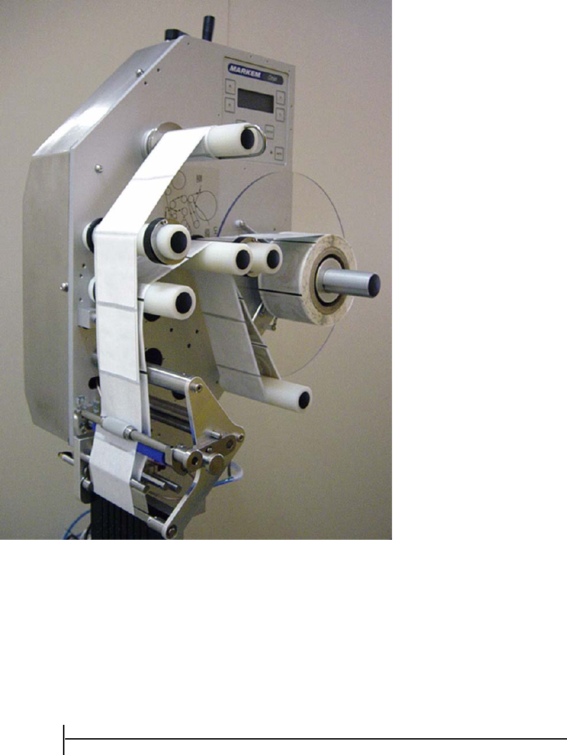
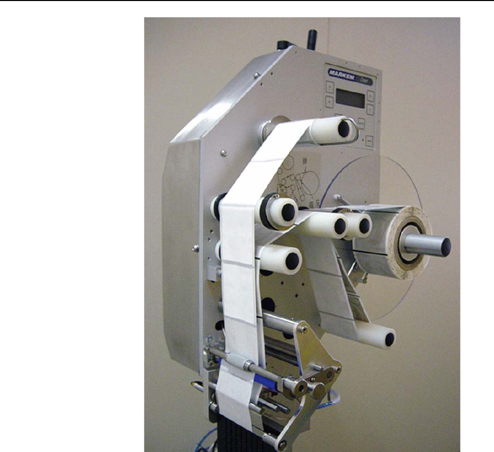
0855904enb 4/05 m®1–25
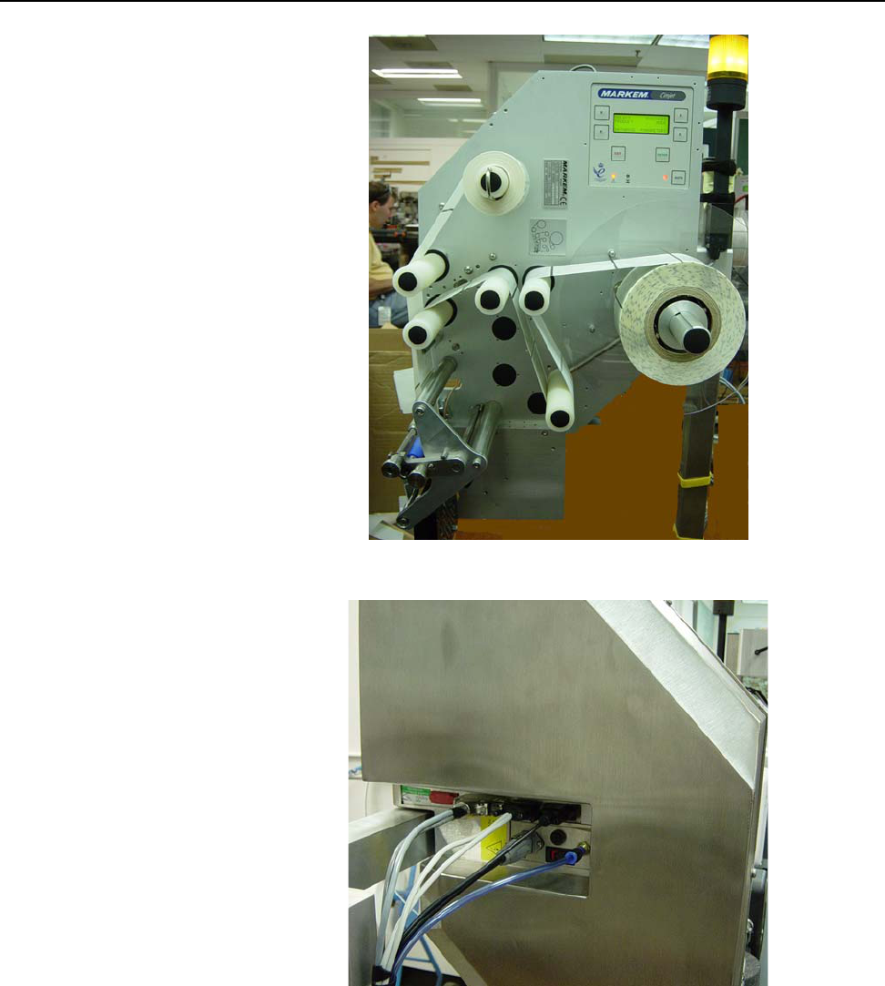
Figure 1–1 Cimjet RFID Dispenser (left-hand option shown)

SECTION 1 General Information
1–26 m®0855804enb 4/05
3.1 Components of Cimjet RFID
The Cimjet RFID consists of a Dispenser and an Applicator.
The main components of the Cimjet RFID are shown in Figures 1-2,
1-3, and 1-4. In addition, Cimjet RFID is usually supplied with an
adjustable height stand.
3.1.1 Dispenser
The tag dispenser provides the tag supply and can be left-hand or
right-hand. It consists of:
• Tag drive
• Sensors for tag control
• Operator interface
The dispenser is the main body of the Cimjet RFID and supports a
variety of different mountable applicator modules.
3.1.2 Applicator
Several modular applicators are available to meet your different
requirements.
The different applicators apply tags in different ways (for example:
air-blow, or telescopic tamp). The choice of applicator also
determines the face of the product that is tagged.
The applicator selected may vary from the type shown in the
following figures.
For more applicator information, refer to the Cimjet RFID Blow
Applicator Manual (0855906) and the Cimjet RFID Tamp
Applicator Manual (0855907).
3.2 Tag Sizes
Tag sizes are applicator-specific.
For more information, refer to the Cimjet RFID Blow Applicator
Manual (0855906) and the Cimjet RFID Tamp Applicator Manual
(0855907).
SECTION 1 General Information
0855904enb 4/05 m®1–27
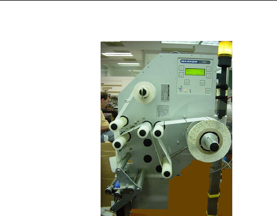
Figure 1–2 Cimjet RFID - Front
Figure 1–3 Cimjet RFID - Rear
SECTION 1 General Information
1–28 m®0855804enb 4/05
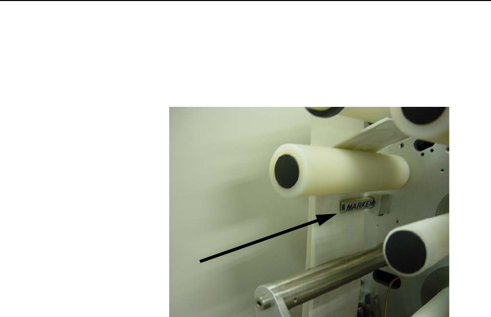
Figure 1–4 Cimjet RFID - Tag Optic

SECTION 1 General Information
0855904enb 4/05 m®1–29
3.3 Beacon Light (Optional)
The beacon light is situated in a prominent position on the Cimjet
RFID. The beacon has a three light system: green, blue, yellow.
• When the yellow light is on, the Cimjet RFID has switched out of
Auto Mode (to Set Mode) or there is a fault on the machine
• When the green light is on, Cimjet RFID is awaiting a signal to
start the Program, Verify, Reject, Apply sequence
• When the blue light is on, the tag is programmed successfully
and is ready to carry out the apply process
3.4 Networking
Cimjet RFID provides options for communicating with PCs and other
computers. The methods available are:
• A Serial link to a single PC
• Ethernet link
SECTION 1 General Information
1–30 m®0855804enb 4/05
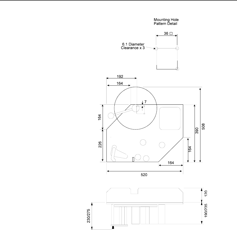
4.0 Dimensional Drawings (in Millimeters)
Figure 1–5 Cimjet RFID - Dispenser (applicator not shown)
SECTION 1 General Information
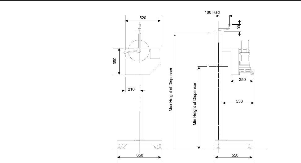
0855904enb 4/05 m®1–31
Figure 1–6 Cimjet RFID - Dispenser Stand

SECTION 1 General Information
1–32 m®0855804enb 4/05

Cimjet ® RFID
Operation/Service Manual
m
®
SECTION 2
Installation Guide

SECTION 2 Installation Guide
0855904enb 4/05 m®2–1
1.0 Installation of the Cimjet RFID
Installation should only be performed by qualified and trained
personnel; customer installation should be sanctioned by MARKEM.
WARNING: Failure to perform installation as stated above will
invalidate the machine warranty.
1.1 Installation Requirements
Ensure that the required services and control signals are available:
• Power: 110-240V single phase power supply rated at 300VA
continuous (750VA maximum at switch on)
• Compressed air: a dry, clean, non-lubricated air supply at 6.2
Bar (90psi)
• Trigger signals depending on the application
• Sufficient space for installation and operation
WARNING: All applicator cylinders have been factory-set to
1.86 Bar for safety. If the cylinders are operated
over 1.86 Bar, the machine must be protected by
guarding, supplied by the customer.
SAFETY: Do not adjust the applicator regulator pressure
above 1.86 Bar under any circumstances. Doing so
could make the Cimjet RFID unsafe.
CAUTION: It is essential that the connector dust covers
provided with the machine are fitted to all unused
connectors to protect against dust and dirt and
prevent possible static damage to internal
components.
SECTION 2 Installation Guide
2–2 m®0855904enb 4/05
2.0 Power
The power connector (Type STASEI2) is supplied with the machine
and conforms to EC regulations.
2.1 Power Configuration
Before installing the machine, check that the power supply is
correctly configured.
The power supply is configured by:
• Power connections to the toroidal transformer located at the rear
of the machine
• Fitting of the corresponding fuse
Details of this procedure are given in Section 7 - Technical
Information.
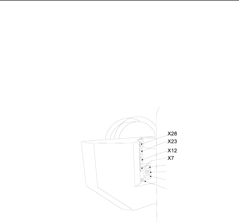
Figure 2–1 External Connectors
For full details of electrical connections, see Section 7 – Technical
Information and Section 10 – Parts Illustrations and Electrical
Schematics.
Power Connector
Power ON/OFF Switch
Fuse
Compressed Air Input
SECTION 2 Installation Guide
0855904enb 4/05 m®2–3
3.0 Air Requirements
A compressed air supply is normally required by the Cimjet RFID to
drive the applicator module. This must be set to 6.2 Bar (90psi) with
a minimum flow rate of 4cfm (cubic feet per minute) (113 liters/
minute) and should be dry, uncontaminated air which should not be
lubricated.
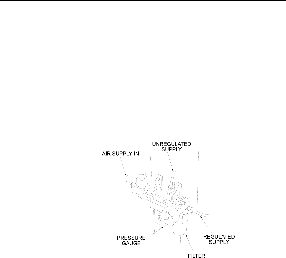
3.1 Air Regulator
A filter regulator assembly is fitted to the base of the stand; this is
comprised of a manual isolation valve, a water trap and pressure
regulator. The air supply is via a 6mm or 8mm flexible pipe.
A single connection is supplied to the main filter regulator unit; from
here, the regulated supply goes to the applicator (if air operated)
and the unregulated supply goes to the air input on the dispenser.
to dispenser
to applicator

SECTION 2 Installation Guide
2–4 m®0855904enb 4/05
4.0 I/O Interface
Connections for all sensors and solenoids are accessed by
removing the rear cover. External I/O is connected via the External
I/O connector (25-way D-type connector (X12)) located on the rear
of the Cimjet RFID.
For full details, see Section 7– Technical Information.
5.0 Positioning the Applicator
The Cimjet RFID is normally supplied with a stand which allows the
positioned tag height on the product to be adjusted within a limited
range. The applicator height will be determined by the conveyor
height and required position of the tag on the product.
Leveling feet are not provided as standard, so care should be taken
to align the machine with the product transportation system.
Before final positioning, the machine should be placed so that the
applicator arm is square to the product and the position of the
machine provides the correct tag position on the product.
CAUTION: If the machine is not secured to the floor, it is
possible for the machine to gradually change
position during use. It is, therefore, important to
mark the provisional position of the machine prior
to starting tagging trials.
Installation drawings are available which show the range over which
the Cimjet RFID can apply tags. Refer to the previous pages in this
section and also to Section 10 – Illustrations and Schematics.
For more applicator information, refer to the Cimjet RFID Blow
Applicator Manual (0855906) and the Cimjet RFID Tamp
Applicator Manual (0855907).

Cimjet ® RFID
Operation/Service Manual
m
®
SECTION 3
Operating Guide

SECTION 3 Operating Guide
0855904enb 4/05 m®3–1
1.0 Preparing Cimjet RFID for Operation
Installation of Cimjet RFID would normally be carried out by a
qualified MARKEM service technician. This would usually involve
connecting an apply sensor to the product conveyor transport
system. The application cycles and type of apply sequence required
would also be set up in the Cimjet RFID applicator parameters. For
full details on connections, please consult Section 7 – Technical
Information.
2.0 Operating the Cimjet RFID
Once the Cimjet RFID has been installed and checked for safety,
the machine can be loaded with tags ready for use.
3.0 Loading Tags
Cimjet RFID uses inside-wound tags.
To load tags, do the following:
• Load a full tag reel onto the tag supply shaft, ensuring that the
tags are facing the correct direction.
• If the tag roll does not have a lead-in with tags on it, remove
approximately 1 meter (1.09 yards) of tags from the backing
web.
• Manually adjust the outside guide collars on the drive rollers to
accommodate the width of the tag roll. The tag roll should not rub
on the collars.
• Feed the backing web around the idler rollers, between the
optional post and the RF shield, around the peel bar and
between the drive rollers (removal of some tags makes this
easier). The optional post is provided to guide the label vertically
down to the peel bar. It should be used in all cases where it does
not interfere with the RF antenna placement.
• Thread the tags onto the machine, ensuring that the tags pass
though the tag gap optic. Do not stick the tag web to the roller.
• Feed the backing web around the drive roller and secure to the
waste web rewind shaft with the clip provided.
• Manually wind the web so that the tag at the peel bar is located
1mm to 3mm (0.039” x 0.118”) beyond the peel edge.
• Secure the nip roller.
• Adjust the position of the RF antenna so that it is close to the RF
chip in the tag. The antenna should not rub on the tag.
• The reel of tags used on this machine may be heavy. Be sure to
take appropriate precautions when loading tags to prevent injury.
• An optional clear plastic disk and clamp are provided to hold the
supply roll on the supply shaft.
SECTION 3 Operating Guide
3–2 m®0855904enb 4/05
Figure 3–1 Webbing Diagram (left-hand option shown)

SECTION 3 Operating Guide
0855904enb 4/05 m®3–3
4.0 Power-up
To prepare the machine for use:
• To turn the air supply ON; rotate the air supply control valve
handle.
• Check that tags are correctly loaded and that the nip roller is
latched in position.
WARNING:Be aware that free items, such as loose clothing or
long hair, could become entangled or trapped in the
tag nip roller or paper path during the operation of
the machine. A warning sticker highlights the
hazard.
• Make sure that the power cable is connected, and switch on the
power at the rear of the machine.
• During power-up, the user interface defaults to Set Mode and
displays the current software version.
• Press AUTO.
• The Cimjet RFID automatically feeds Datum tags to set the
correct tag stop position and measure the length of the tags in
use. The number of tags varies with software versions.
The message: REMOVE DATUM TAGS, THEN PRESS AUTO is
displayed on the user interface. To continue:
• Remove the tags.
• Press AUTO.
The Cimjet RFID is now ready to operate.
SECTION 3 Operating Guide
3–4 m®0855904enb 4/05
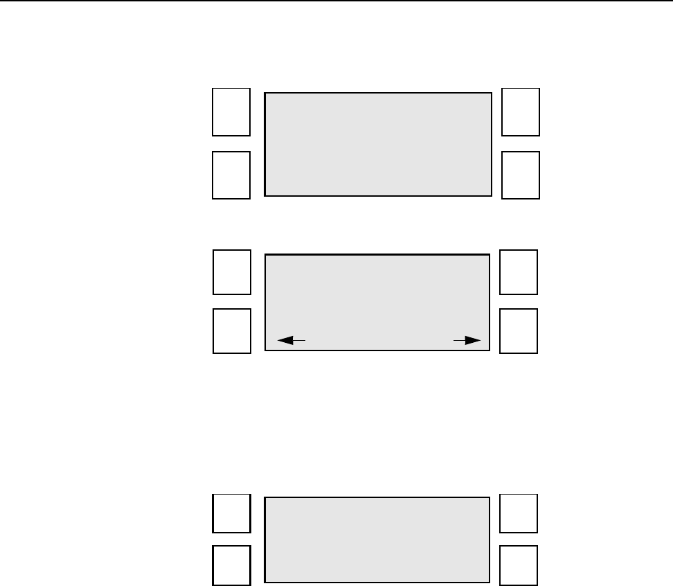
5.0 Operator Interface
5.1 Menu Operation
The control panel (user interface) provides:
• Machine setup and fault finding
• Error and Warning Messages
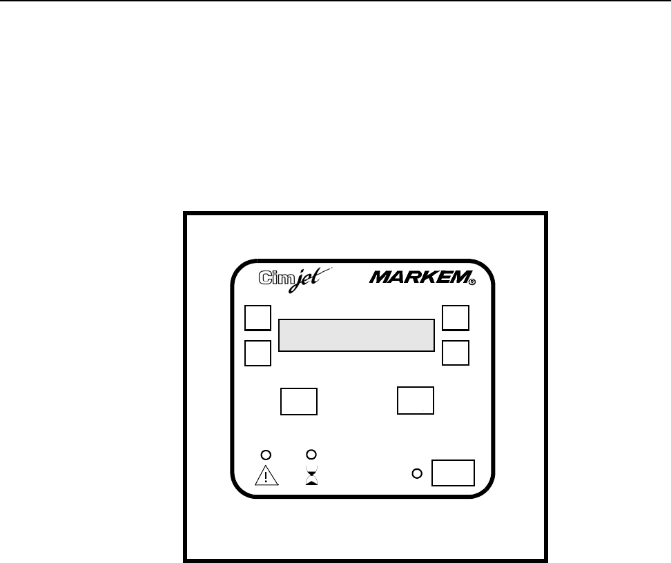
5.2 The Control Panel
This drawing is a representation and is not to scale.
• Four option soft keys
• Liquid Crystal Display (LCD) with 4 lines of 20 characters
• Three fixed keys: EXIT, ENTER, and AUTO
Exit Enter

SECTION 3 Operating Guide
0855904enb 4/05 m®3–5
5.3 Operator Interface LEDs
Three LEDs provide a visual indication of machine status.
5.4 Guidelines for Entering Data
Many of the screens in both Auto and Set Mode require the
operator to enter information using the menu.
To select an option:
• Press the ‘soft key’ next to the required option.
NEXT and PREVIOUS
Generally only one parameter can be displayed on the screen at
one time.
To scroll through available options:
• Press NEXT to view the next available parameter
• Press PREVIOUS to view the previous available parameter
Saving and Discarding Changes
The method of saving and discarding changes depends on the
particular screen. Generally, to save changes:
• Press ENTER; the new parameter value is saved
To discard changes and retain the previous value:
• Press EXIT
Also press EXIT to step back up through the menu structure.
LED Description
Mode LED Indicates if the machine is in
Auto or Set Mode
Green LED: Auto Mode
Red LED: Set Mode
Machine
Busy LED Yellow LED: Cimjet RFID is
feeding or applying in Auto
Mode
Status LED Green LED: Machine OK
Amber / Yellow LED: Warning,
such as low paper
Red LED: Fault, such as no tags

SECTION 3 Operating Guide
3–6 m®0855904enb 4/05
6.0 Auto and Set Mode
The Cimjet RFID has two modes of operation:
• Auto Mode
Cimjet RFID automatically responds to Apply signals. Application
is triggered by sensors or other inputs. For further details, refer to
the Cimjet RFID Section 7-Technical Information.
• Set Mode
This mode provides a series of menus which allow you to:
a) Run diagnostic tests
b) Control applicator parameters such as apply delays, etc.
c) Set the time and date
Fixed Keys
•
•
•
This AUTO key is used in place of a keyswitch and toggles
Cimjet RFID between Auto and Set Mode.
ENTER
EXIT
SECTION 3 Operating Guide
0855904enb 4/05 m®3–7
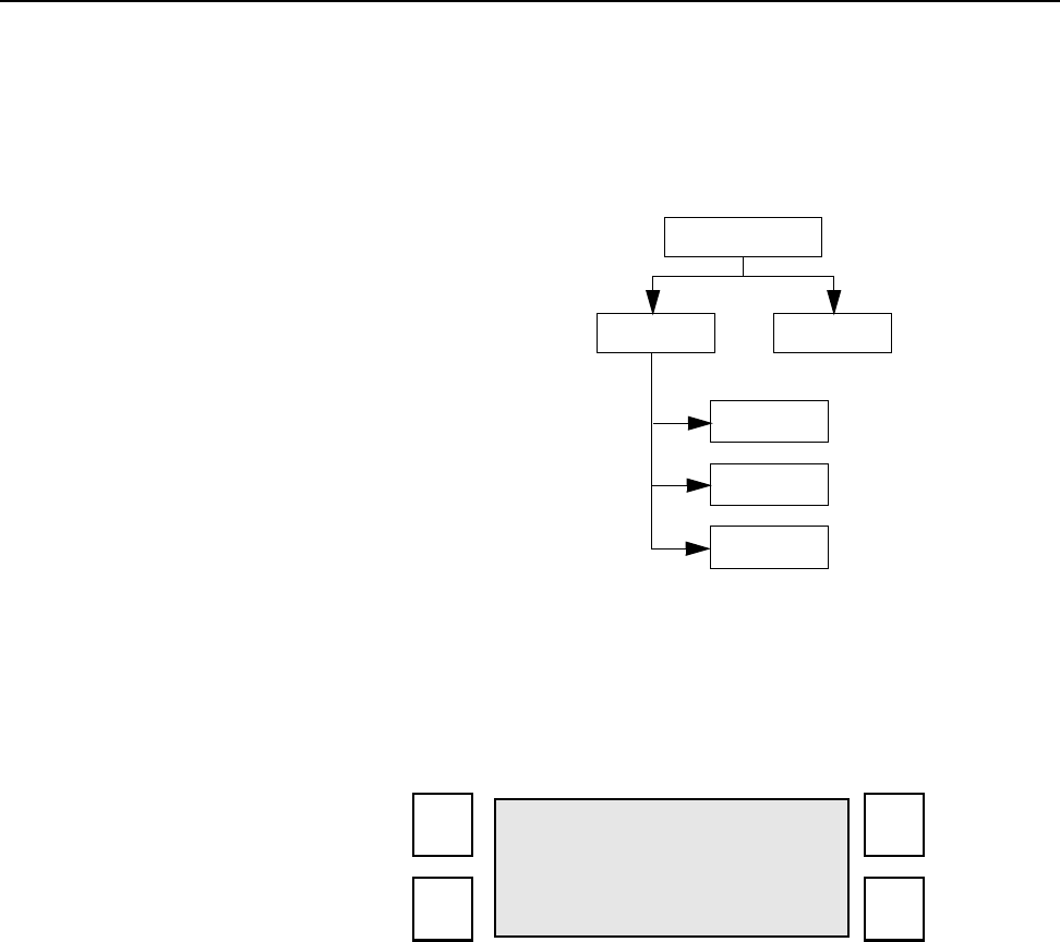
6.1 Auto Mode
In Auto Mode, Cimjet RFID automatically applies tags.
Application is triggered by sensors or other inputs such as PLC
control. For details, refer to the Cimjet RFID Section 7-Technical
Information.
Figure 3–2 Auto Mode Menu Tree
To select Auto Mode:
• Press AUTO
The Auto Mode LED is green and the following LCD screen is
displayed:
:
COUNTS TEST
NEXT
PREV
RESET
AUTO
COUNT: 0
TEST COUNTS
SECTION 3 Operating Guide
3–8 m®0855904enb 4/05
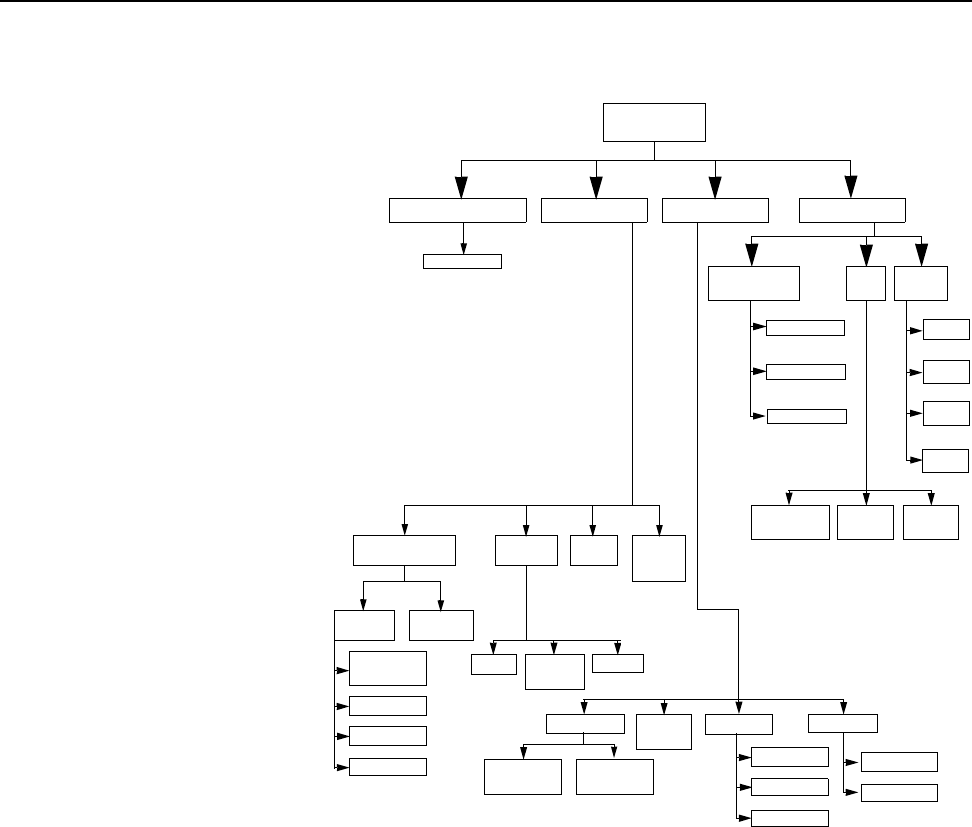
6.2 Set Mode
In Set Mode, Cimjet RFID does NOT respond to Apply requests.
Figure 3–3 Set Mode Menu Tree
SET
MODE
PARAMETERS
TIME /
DATE MOVE
PRINT
CIM3
-X
+X
-Y
+Y
VIEW TIME /
DATE SET
DATE SET
TIME
DIAGNOSTICS MANUAL TEST
FEED SET TAG
OPTIC
DISP
I/O
INPUTS /
OUTPUTS
TIMINGS
FEED FEED/
APPLY
APPLY RIBBON
FEED
TOGGLE
NEXT
PREV RETRIEVE
TAG RETRIEVE
ALL
RETRIEVE FREE
SPACE DELETE VIEW
DATABASEENGINEER MODESELECT PRODUCT
SET
PARAMETER
NEXT
PREV
CHANGE
NEXT
PREV
NEXT
PREV
DELETE

SECTION 3 Operating Guide
0855904enb 4/05 m®3–9
Set Mode provides a series of menus which allow you to:
• Run diagnostic tests
• Control applicator parameters
• Set the time and date
Cimjet RFID has a further level of restricted access menus, which
give access to other infrequently changed parameters. For further
information, see Section 4 - Restricted Access Mode User Guide.
To select Set Mode:
• Press AUTO
The display shows the four main options available:
SELECT ENGINEER
PRODUCT MODE
DATABASE PARAMETERS

SECTION 3 Operating Guide
3–10 m®0855904enb 4/05
7.0 Engineer Mode
These options provide a number of first line machine maintenance
functions:
7.1 Diagnostics
Disp I/O
This screen allows the operator to view the current status of the
Cimjet RFID inputs and to test the various Cimjet RFID Outputs.
Full details can be found in Section 7 – Technical Information.
7.2 Set Tag Optic
Cimjet RFID feeds tags to automatically determine the optimum
setting for the tag sensor. This function can be used, if for example,
different tag stock is used.
DIAGNOSTICS MANUAL
TEST SET TAG
DISP I/O TIMINGS

SECTION 3 Operating Guide
0855904enb 4/05 m®3–11
8.0 Parameters
This option allows the operator to alter various operating
parameters:
Time / Date
• Enter the required date and time
Time is entered in the 24-hour format.
TIME/ SET
DATE PARAMETERS
VIEW TIME/DATE
SET SET
TIME DATE

SECTION 3 Operating Guide
3–12 m®0855904enb 4/05
Set Parameters
This lists the Set Parameters available to view and/or change.
Other parameters are also available; for further information, refer to
Section 4 - Restricted Access Mode User Guide.
*Does not apply to Cimjet RFID
Table 3–1
Parameter Description
Apply Delay
25
This parameter allows the
application of the tag onto the
package to be delayed. It is used for
positioning.
Darkness*
100
Feed Speed
Range: 50-
250mm/s
Default: 15
0mm/s
Feed speed (mm/s) is the time taken
for the tag to pass the nip roll.
Direction*
0

Cimjet ® RFID
Operation/Service Manual
m
®
SECTION 4
Restricted Access Mode User Guide

SECTION 4 Restricted Access Mode User Guide
0855904enb 4/05 m®4–1
1.0 Restricted Access Mode User Guide
The Restricted Access Mode in Cimjet RFID, has a series of
menus. These menus allow the configuration to be altered.
CAUTION: The accessed parameters should only require
changing directly after installation. Access
parameters must be changed by qualified MARKEM
personnel or under close instruction from MARKEM.
2.0 Entering Restricted Access Mode
To enter Restricted Access Mode:
• Select Set Mode
• Press and hold the ENTER and EXIT keys
After approximately five seconds, the restricted access main menu
appears. Release the EXIT key first.
The restricted access main menu has four main options:
• Restricted Setup
• Machine Init (Initialization)
• Password
• Cycle
Further details on these menus can be found on the following
pages.
RESTRICTED MACHINE
SETUP INIT
PASSWORD CYCLE

SECTION 4 Restricted Access Mode User Guide
4–2 m®0855904enb 4/05
3.0 Machine Init (Initialization)
From the main menu:
:
• Press MACHINE INIT
The Machine Init menu is displayed:
3.1 Reset Params
This option resets all parameters to their default values. The current
selected applicator is not changed, but the applicator parameters
are set to the corresponding default values.
From the Machine Init menu:
• Press RESET PARAMS
The following screen is displayed:
:
RESTRICTED MACHINE
SETUP INIT
PASSWORD CYCLE
RESET CLEAR
PARAMS DATABASE
COUNTS
CLEAR
FLASH FILE
RESET PARAMETERS
ARE YOU SURE?
YES NO

SECTION 4 Restricted Access Mode User Guide
0855904enb 4/05 m®4–3
4.0 Password
Cimjet RFID can have password protection of the various Set Mode
functions.
Passwords are entered using the four soft keys. These keys are:
An asterik (*) will be displayed for each digit entered, and the
ENTER key should be pressed when the complete password has
been typed.
The passwords for each access level are fixed. The key sequences
are given on the last page of this section. This page may be
removed if passwords are being used, and if this manual is freely
available.
When a password is enabled for a key, Cimjet RFID will request
entry of the key sequence before allowing access to the option. The
four levels are for access by different user types:
• Level 1 - Operators
• Level 2 - Line Supervisors
• Level 3 - Maintenance Personnel
• SYSTEM - MARKEM Personnel and Line Managers
12
43
SECTION 4 Restricted Access Mode User Guide
4–4 m®0855904enb 4/05
4.1 Password Configuration
On selection of the PASSWORD option from the top level restricted
access menu, the following screen is displayed:
• Select CHANGE; the following screen is displayed:
:
The NEXT and PREVIOUS keys are used to scroll through the four
access levels.
To activate a specific button on any level, press ENABLE with the
cursor flashing on the required function (- E---) indicates which
functions are available to users of this password level.
CHANGE
LEVEL 1
- ----
NEXT PREVIOUS
ENABLE DISABLE
LEVEL 1
- ----
ENABLE DISABLE
LEVEL 1
- E---

SECTION 4 Restricted Access Mode User Guide
0855904enb 4/05 m®4–5
In the above example, LEVEL 1 has access, via the level 1
password, to the SELECT PRODUCT option (Button 1).
The underscores on the screen indicate which function button is
associated with the button numbers shown at the beginning of this
section.
For example, reading from left to right, the first underscore activates
the Restricted Setup buttons (ENTER and EXIT pressed at the
same time). The next underscores are buttons 1, 2, 3, and 4.
Access to the other soft keys and restricted access mode will
depend on the other users’ protection level.
If all users have a ‘-’ for a particular key (or restricted access), then
no password protection will exist on that key.
The protection level for the particular user may then be changed
using the soft keys.
Note: The SYSTEM password, when active, will allow access to
change the password settings.

SECTION 4 Restricted Access Mode User Guide
4–6 m®0855904enb 4/05
4.2 Password Key Sequences
The Key sequences for each access level are fixed and are as
follows:
• Level 1 – 2-1-1-1
• Level 2 – 2-3-3-1
• Level 3 – 4-1-2-3
• System 4 – 2-4-4-1
CAUTION: If you have password protection to restricted access
mode, the SYSTEM user will automatically have
access to this mode regardless of the SYSTEM
password configuration. The SYSTEM user will be
the only user with access to the password
configuration menus.
Note: Remove this page if this manual is in common circulation and
passwords are in use.

SECTION 4 Restricted Access Mode User Guide
0855904enb 4/05 m®4–7
5.0 Cycle
This cycle option allows the various elements of the machine to be
set into continuous operation (for example: to continuously cycle the
Cimjet RFID unit).
See the main menu below:
• Select CYCLE; the following screen is displayed:
To start a cycle:
• Press the required soft key
To stop the cycle:
• Press the required soft key again
RESTRICTED MACHINE
SETUP INIT
PASSWORD CYCLE
FEED APPLY
CYCLE
CYCLES/MIN
FEED/APPLY FEED

SECTION 4 Restricted Access Mode User Guide
4–8 m®0855904enb 4/05
6.0 Restricted Setup
From the main menu:
• Press RESTRICTED SETUP
The following screen is displayed:
7.0 Set Parameters
This option allows various parameters to be viewed and changed.
From Restricted Setup menu:
• Press SET PARAMETERS
The Set Parameters screen is displayed:
The operator can change:
• Feeder Parameters
• Communications Parameters
• Machine Options
SET NODES
SET SELECT
PARAMETERS LANGUAGE
FEEDER COMMS.
MACHINE
OPTIONS TAG

SECTION 4 Restricted Access Mode User Guide
0855904enb 4/05 m®4–9
8.0 Communications Parameters
These parameters configure the Communications port.
From the Set Parameters screen:
• Press COMMS
The first parameter is displayed:
.
• Press CHANGE to select a different option
See the following table for a full list of available communications
parameters.
FEEDER COMMS.
MACHINE
OPTIONS TAG
CHANGE
EMULATION MODE
CIMCOMMS
NEXT PREVIOUS

SECTION 4 Restricted Access Mode User Guide
4–10 m®0855904enb 4/05
*Does not apply to Cimjet RFID
Table 4–1 Communications Parameters
Parameter Description
Emulation Mode
Range: CIMCOMMS,
EMULATION Z or S
Default: CIMCOMMS
Determines whether the
Cimjet RFID Host
communication channel
is set to respond to
CIMCOMMS protocol or
desktop EMULATION
protocol
Comms Baud
Range: 2400, 4800, 9600,
19200, 38400, 57600, 115200
Default : 19200
Host communications
link baud rate
Comms Link
Range: RS232
ETHERNET
Default: RS232
Host communication link
type
Comms Mode
Range: LOCAL, SLAVE
Default: LOCAL
In SLAVE mode, the
Cimjet RFID responds to
remote product select
commands
Network Node*
Range: 1 to 31
Default: 1 (RS232 operation)
Transfer Timeout
Range: 30 seconds to 10
minutes
Default: 30 seconds
This allows the
download transfer
timeout to be increased

SECTION 4 Restricted Access Mode User Guide
0855904enb 4/05 m®4–11
9.0 Machine Options Parameters
These parameters configure the machine options available.
From the Set Parameters screen:
• Press MACHINE OPTIONS
The following screen is displayed:
This screen provides access to:
• Applicator Parameters
• Machine Options
• Laser Setup Parameters
FEEDER COMMS
MACHINE
OPTIONS TAG
APPLICATOR
MACHINE
CONFIG

SECTION 4 Restricted Access Mode User Guide
4–12 m®0855904enb 4/05
9.1 Machine Configuration Parameters
These parameters configure various machine setup options:
From the Machine Option screen:
• Press MACHINE CONFIG
The first parameter is displayed:
The options can be accessed by using the NEXT and PREVIOUS
soft keys.
APPLICATOR
MACHINE
CONFIG
CHANGE
MACHINE TYPE
CIMJET RFID
NEXT PREVIOUS

SECTION 4 Restricted Access Mode User Guide
0855904enb 4/05 m®4–13
Table 4–2 Machine Configuration Parameters
Parameter Description
Machine Type
Range RFID: 306, 311, 312,
313, 314P, 316, 321, 331,
334, 342, 344, 345, 346,
2112, 2113, 2132, 2341,
2422, Cimpak 300
Default: RFID
These options are for the
Cimjet series machines and
define the Applicator type
fitted.
Database Mode
Range: LOCAL RAM, Host
PC
Default: LOCAL RAM
Cimjet RFID has two methods
of product selection:
Local RAM Mode: Cimjet
RFID selects tags resident in
the local memory
Host PC Mode: Cimjet RFID
requests the required data
from the Host PC
Sensor Debounce
Range: 0 to 2000
Default: 0
Delays the response to
external sensors
This is useful, for example, if
the shrink wrap on a product
is causing the product sensor
to trigger a number of times
for each pack.
By setting a higher Sensor
Debounce value, Cimjet
RFID only responds to signals
that stay on or off for the
debounce time.
Enable Counts in Run
Range: Yes, No
Default: Yes
Allows the product counts to
be displayed on the RUN
Mode screen.
Test In Run
Range: Yes, No
Default: Yes
Most applicators provide a
TEST option in RUN Mode
that allows a tag to be fed
without an external signal.
Set to No to disable this
function.

SECTION 4 Restricted Access Mode User Guide
4–14 m®0855904enb 4/05
Allocation Warning
Range: Off, On
Default: Off
If set to On, a warning is
displayed when an allocation
runs out.
Measurement Units
Range: Metric, Imperial
Default: Metric
Style in which measurements
are displayed, either Metric or
Imperial
Filter Select
Range: Off, On
Default: Off
If set to On, it allows operator
to search for a product using
a filter. Example: first letter of
the product name A* or 3*
Only product names
beginning with A or 3 will be
displayed.
Allocation Abort
Range: On, Off
Default: Off
An allocation set from
CimControl® can be stopped
before it is completed.
Log Feed Data*
Range: No, To File, Realtime
Default: No
Status Output
Range: None, Apply complete
or Cycle complete
Default: None
Used with external control
systems
Status Output Reset
Range: Product Select/UD,
Apply, Reset Input
Default: Product Select/UD
This determines which
function will be used to reset
the Status Output.
CimComms Status Reset
Range: Product Select/UD,
Apply, Reset Input
Default: Product Select/UD
This determines which
function will be used to reset
the CimComms Status
Word.
Used with either Cimcomms
or ASCII Comms status
messages
Table 4–2 Machine Configuration Parameters
Parameter Description

SECTION 4 Restricted Access Mode User Guide
0855904enb 4/05 m®4–15
Note: For full information on the last five parameters, please see
Section 7 – Technical Information.
*Does not apply to Cimjet RFID
Compatibility Mode
Range: On or Off
Default: On
This determines if the
CimComms Status Reset
function is used or not.
Product Select Input*
Range: On, Off
Default: Off
Key Beep
Range: Yes, No
Default: No
When a key is pressed, a
‘beep’ noise is produced.
Table 4–2 Machine Configuration Parameters
Parameter Description

SECTION 4 Restricted Access Mode User Guide
4–16 m®0855904enb 4/05
9.2 Applicator Parameters
These parameters configure various applicator setup parameters.
*Does not apply to Cimjet RFID
Table 4–3 Restricted Setup/Set Parameters/Machine Options/
Applicator
Parameter Description
Operation Mode
Default: On-
demand
Selects from Auto Apply, Pre-
fed, and On-demand Mode.
These modes are described in
Section 2.
Blow Time
Default: 50
Sets the duration of the blow
used to apply the tag. This should
be kept as short as
possible while maintaining
reliable tag application. It is
recommended that the Blow
Time is on for the time it takes
the tag to blow from the grill to
the product.
Settling Time
Default: 0
This parameter is used to allow
the tag to settle to the applicator
grill before the tag is applied to
the product.
Apply Delay
Default: 25
This parameter allows the
application of the tag onto the
pack to be delayed. Used for
positioning.
Head Lift Delay
Default: 140
On Cimjet RFID, this is used to
time the cylinder for the reject
mechanism.
Op Vacuum
Delay*
Default: 100

SECTION 4 Restricted Access Mode User Guide
0855904enb 4/05 m®4–17
10.0 Feeder Parameters
These parameters configure options in the Cimjet RFID for tag
adjustment, motor speed, and optic sensor position.
Table 4–4 Restricted Setup/Set Parameters/Feeder
Parameter Description
Darkness %*
Default: 100
Backfeed Speed*
Default: 150
Feed Adjust
Default: -50 Adjusts the position of the leading
edge of the tag on the peel edge
Backfeed
Default: 0 Backfeed must remain at 0 for
Cimjet RFID.
Ribbon Sensor*
Feed Speed
Default: 150
Feed Speed (mm/s) is the time
taken for the tag to pass the nip
roll.
Optic Position
Default: NEW
Sensor location prevents tag gap
from stopping in front of sensor
(refer to Section 6,
paragraph 3.0).
Optic Adjust
Default: 0
If the tag gap happens to stop in
the Tag Gap sensor, this will
cause feed problems. In cases
where this happens, the Tag Gap
sensor can be moved to a new
position 10mm (.394”) lower.
The Optic Adjust parameter
should then be adjusted by -100
to compensate.
NOTE: This parameter should
not be adjusted for any other
reason.
Direction*
Default: 0
Ribbon Save*
Default: None

SECTION 4 Restricted Access Mode User Guide
4–18 m®0855904enb 4/05
*Does not apply to Cimjet RFID
Feeder Hand
Range: LEFT,
RIGHT
Default: LEFT
Defines on which side of the
feeder the image is aligned
Table 4–4 Restricted Setup/Set Parameters/Feeder
Parameter Description

Cimjet ® RFID
Operation/Service Manual
m
®
SECTION 5
Operating Modes

SECTION 5 Operating Modes
0855904enb 4/05 m®5–1
1.0 Operating Modes
The Cimjet RFID can be fitted with various applicator modules to
suit specific applications. The application may require that tags be
applied to the top, front, side, front and side or top and side of the
product packs.
The type of application required and the number of packs/minute will
determine which style of applicator is best suited for the job.
In most cases, the Apply sequence is triggered by a sensor
mounted on the transport conveyor.
In some special applications, the Apply sensor may be dispensed
with and the required functions performed using a serial
communications link.
Three factors determine the position of the tag on the pack:
• The position of the applicator relative to the conveyor
• The position of the sensor
• The setting of the Apply Delay timer
Any one of these factors can affect the position of the tag placement
in the direction of the product motion.
A suitable combination of these factors must be determined.
Note: The machine should, in most cases, be mounted square to
the products.
2.0 Application Cycle
Three options are normally available, depending on the applicator
being used:
Auto Apply: Feed sensor only
Pre-feed: Apply sensor only
On Demand: Feed sensor and Apply sensor
Note: Feed and Apply sensors will only be operational when the
Run Mode is implemented, and the dispenser positions the
applicator to its Home position.

SECTION 5 Operating Modes
5–2 m®0855904enb 4/05
2.1 Auto Apply Mode
The dispenser detects a product by using the Feed sensor, and
begins to feed a tag.
During feed, an air assist jet is used to ensure that the tag comes
into contact with the applicator apply mechanism.
The applicator may be in the form of a vacuum pad or belt-driven
applicator.
When the feed is completed, the air assist jets hold the tag to the
applicator.
The applicator waits for the apply delay timer to elapse, then
activates the apply mechanism
Note: No Apply sensor is used.
2.2 On Demand Mode
In this case, the sequence is similar to Auto Apply, except that this
time both Feed and Apply signals are used.
The Feed sensor is activated and the tag is fed onto the applicator.
After the tag is dispensed, Cimjet waits for the Apply signal.
The Apply sensor is activated; the applicator waits for the apply
delay timer to elapse, and then it applies the tag.

SECTION 5 Operating Modes
0855904enb 4/05 m®5–3
3.0 Connecting External Sensors
3.1 Wiring the Sensors
The Feed and Apply sensors are connected to Cimjet RFID via the
9 pin D type connector X23 on the rear of the machine.
Depending upon the installation, different wiring configurations can
be used.
In simple applications using only Feed and Apply sensors, wire
the sensors directly to X23.
In more complex applications that require a number of
connections to X23, it is recommended that a single multi-core cable
be run in conduit to a junction box. The junction box can be mounted
at a convenient position and individual cables run to the sensors and
conveyor control, etc.
For full connection details, refer to Section 7 – Technical
Information.
3.2 Testing the Sensors
Viewing the status of the inputs in the Engineer Mode Diagnostic
screen will test the functionality of the sensors. Take the Cimjet out
of Auto Mode; depress the Engineer Mode button, then depress
the Display I/O button. The status of the inputs can then be seen.
Passing an object in front of the sensor should cause the status to
change from OFF to ON.

SECTION 5 Operating Modes
5–4 m®0855904enb 4/05
4.0 Positioning Sensors
Depending on the mode of operation, set via the Restricted
Parameters menu, the Cimjet RFID can use a combination of Feed
sensor only, Apply sensor only, or both Feed sensor and Apply
sensor.
The sensors must be positioned correctly to obtain the best possible
results. Different considerations are required for different
operation modes.
4.1 Auto Apply Sensor Position
This mode is useful for applications where the line speed and pack
spacing are constant, and the Apply sensor is not required.
In this mode, the Feed sensor is used and the tag is applied
automatically after the Apply delay timer has elapsed.
The Feed sensor should be positioned far enough away from the
Cimjet applicator (prior to the tag applicator) to allow enough time
for the tag to feed onto the applicator.
To achieve this, set the Apply Delay timer to zero and position the
sensor so that the tag is firmly and fully applied to the pack as early
as possible. Make sure it is applied as close as possible to the
nearest edge. Use the Apply Delay timer to fine-tune the tag’s
position on the pack.
If the conveyor speed varies, the tag position may differ from pack to
pack and, in extreme cases, may even miss the pack completely.
This can be avoided by using On Demand Mode, which requires
both Feed and Apply sensors.

SECTION 5 Operating Modes
0855904enb 4/05 m®5–5
4.2 On Demand Mode Sensor Position
This option is used when the product conveyor is constantly
stopping and restarting, or sometimes slows down due to the weight
of the products.
In On Demand Mode, a Feed sensor triggers the feeding of the tag
and an Apply sensor triggers the application of the tag.
When the Apply sensor is triggered, Cimjet waits for the Apply
Delay Timer to elapse and applies the tag onto the pack.
The Apply sensor position and the Apply Delay parameter setting
determine the position of the tag on the pack.
The product’s pitch (spacing frequency) and speed determine the
position of the Feed sensor.
The sensor must be mounted far enough away from the Cimjet
applicator (prior to the tag applicator) to allow a tag to be fed before
the product reaches the applicator. If this distance is greater than
the product pitch, steps must be taken to increase the feed speed or
to increase the product pitch.
The Apply sensor should be mounted as close to the applicator as
possible. This Apply sensor triggers the application of the tag onto
the pack. The location of this sensor will set the position of the tag
on the pack.
A user parameter (Apply Delay) may be used to delay the
application of the tag, but the zero delay tag position is set by the
sensor position.

SECTION 5 Operating Modes
5–6 m®0855904enb 4/05
5.0 Fitting the Sensors
When the optimum position of the sensors is determined, mount the
sensor firmly in place.
6.0 Apply Delay
The Apply Delay can either be set from the Set Mode Parameter
screen or from the Restricted Access Mode screen.

Cimjet ® RFID
Operation/Service Manual
m
®
SECTION 6
Preventive Maintenance Guide

SECTION 6 Preventive Maintenance Guide
0855904enb 4/05 m®6–1
1.0 General Maintenance and Cleaning
For the best performance of your machine, general cleaning must
be carried out as a normal part of machine use.
This section describes cleaning and maintenance procedures which
will help to keep the Cimjet RFID in good working condition.
1.1 General Information
Carry out a daily general machine inspection, which should include:
• Check all guards to ensure they are correctly fitted using all
required fasteners
• Check that movement is smooth and that slides and cylinders
are not damaged
• Check for wear
• Check for trapped cabling and pipes
• Check for inaccurate tag placement
1.2 Positioning of Safety Labels
Labels are placed on the Cimjet RFID in various positions by
MARKEM to warn of potential safety hazards. As part of regular
maintenance, safety labels must be checked and replaced
whenever any are missing or damaged.
Refer to Section 1 – General Information for further instructions or
information.

SECTION 6 Preventive Maintenance Guide
6–2 m®0855904enb 4/05
2.0 Cleaning of All Rollers
When tags are fed, the tag adhesive may bleed onto the backing
web. This adhesive can build up on the feed roller, tag nip, and idler
rollers which may eventually cause feed problems.
To prevent these problems, the machine must be cleaned regularly
using a suitable cleaning agent such as Isopropanol. Care must be
taken when cleaning to prevent damage to the machine and its
delicate components. Cleaning agents which will damage rubber or
plastic MUST NOT be used. If in doubt, consult MARKEM.
It is recommended that the rollers be cleaned regularly every time
the tags are replaced and before using the machine if it has not
been operated for several days.
• Turn off power to the machine and remove tags
• Use a cotton swab or soft cloth, moistened in Isopropanol, to
remove any residue from the feed roller and the idler rollers
Note: NEVER use abrasive materials or sharp instruments such as
screwdrivers
Refer to safety information in Section 1 – General Information
before using the Isopropanol.

SECTION 6 Preventive Maintenance Guide
0855904enb 4/05 m®6–3
3.0 Changing the Tag Size
When the tag width size is altered, check the following:
• Reposition all the outer tag guide collars to suit the new tag size;
the inner collar position should not be moved
• Ensure that the web nip roller is in the center of the web
When the tag height size is altered, check the following:
• After webbing up the machine, use the Engineer Mode to “set
the tag optic sensor”
• Check that the new tag size gap does not stop in the Gap
sensor
• If the gap between tags does stop in the sensor, the Gap Optic
sensor should be moved to the second hole position and the
Optic Adjust parameter changed by minus 100 (-10mm)
accordingly
• Adjust the Feed Adjust parameters, if necessary, to locate the
front edge of the tag at the peel beak
• Adjust applicator if required
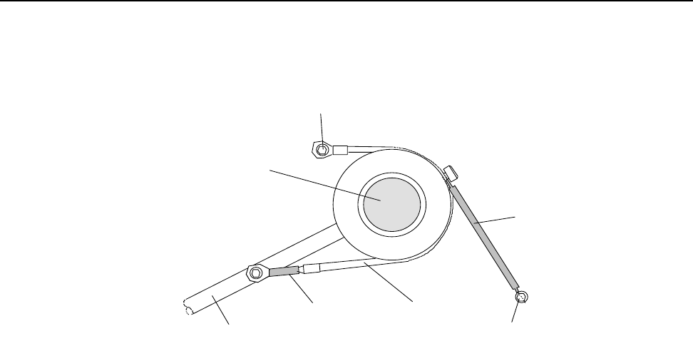
SECTION 6 Preventive Maintenance Guide
6–4 m®0855904enb 4/05
4.0 Tag Unwind Brake
A spring-loaded dancing arm and rubber friction brake band are
used to control the tag supply.
Figure 6–1 Supply Reel Brake for Inside-wound Tags
Each month, check for wear of the rubber friction brake band. If the
brake band or the springs are showing signs of wear, or the brake is
not operating correctly, the brake band should be replaced.
If the brake is not operating correctly, a heavy supply reel will tend to
overrun and introduce slack into the tag supply path.
To replace the brake band:
• Power off the machine
• Turn and lock off the air supply
• Remove the tags from the machine
• Loosen, but do not remove, the two grub screws in the inner
locking ring
• Remove the inner locking ring and the inner Perspex disk
• Unscrew the screws that secure the brake band to the dancing
arm and base plate and fit the new band
WIPE DOWN ARM
SPRING FRICTION BAND
SPRING
WEB SUPPLY ROLLER
FIXING TO BASE PLATE
FIXING TO BASE PLATE
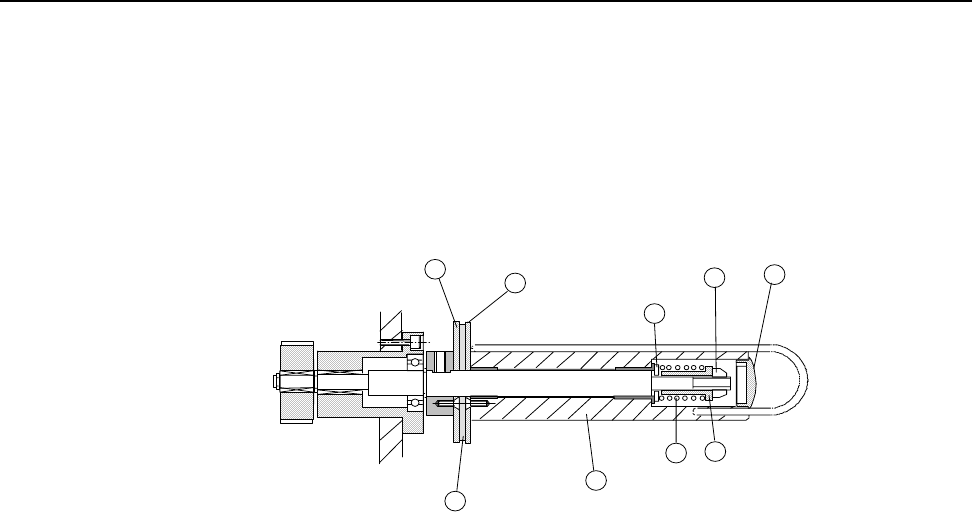
SECTION 6 Preventive Maintenance Guide
0855904enb 4/05 m®6–5
5.0 Clutches
The web take-up roller uses slipping clutches to allow for the
differing speeds of rotation required as the diameters of the web
take-up change.
A special oiled-felt material is used to provide the best performance
over a long period. However, as with any slipping clutch
arrangement, the friction material must be periodically replaced.
.
Figure 6–2 Web Rewind Roller and Clutch
The above illustration (not to scale) shows the detail of the web
rewind roller and clutch.
5.1 Replacing the Felt Pads
When the clutch felt pads need replacement (between intervals of
six months to one year), do the following (refer to Figure 6-2):
• Remove the plastic end cap (1)
• Use a box spanner (deep socket nut driver) (10mm A/F) to
remove the nut (2)
• Remove spring (4), spacer (3) and washer (5); do not lose or
drop these items as they are being removed
• Remove the roller (6) and outer clutch plate (7) by sliding off the
central shaft
• Remove the felt washer (8)
• Replace with a new felt washer from the spares kit; this should
be oiled already. If the pad has dried out, soak it in Roebuck
RB24 oil (from Buck Hickman InOne, U.K.) for 10 minutes, and
allow it to drain for 15 minutes before fitting
• Replace the roller, washer, spacer and nut and set the clutch
torque (see Section 6, paragraph 5.2, “Setting the Clutch
Torque”)
1
2
3
4
5
6
7
8
9

SECTION 6 Preventive Maintenance Guide
6–6 m®0855904enb 4/05
5.2 Setting the Clutch Torque
At machine build, the clutch torques are set using a torque gauge.
The following procedure should be used to set the torque when a
replacement felt is fitted.
Note: To set torque (refer to Figure 6-2):
• Remove the plastic end cap (1)
• Use a box spanner (deep socket nut driver) (10mm AF) on the
nut (2) to adjust the torque; turn the nut clockwise to increase
torque
• To set the torque, first turn the nut counterclockwise until the
clutch slips very easily
• Next, use a pull scale or a 3-lb. (13.3 Newton) weight; hook the
scale or weight to the U-pin; turn the nut clockwise until the
clutch is tight enough to hold a 3-lb. pull at a 90 degree angle to
the diameter of the roller (refer to number 6 in Figure 6.2)
• Replace the plastic end cap when the correct movement has
been obtained

SECTION 6 Preventive Maintenance Guide
0855904enb 4/05 m®6–7
6.0 Sensor Adjustment
6.1 Low Reel Sensor
An optical sensor is used to detect when the supply reel diminishes
below a set level. The sensitivity of the sensor is adjusted by a
screw on the sensor.
6.2 Nip Home Sensor
The position of the nip arm is monitored to ensure that the feeder
and nip arm are correctly in position before feeding starts.
A small, barrel type, inductive sensor is used to sense the position of
the rear of the pivoted nip arm.
To replace this sensor:
• Turn off all power to the machine
• Turn off and lock off the air supply to the machine
• Remove the rear cover
The sensor is located adjacent to the feed roller drive pulley.
• Remove the lock nut and unscrew the sensor
• Close the nip roller
• Screw in the new sensor
Note: There should be a 0.1mm gap between the sensor and the
end of nip arm.
• Secure the lock nut
• Reconnect the sensor wiring
• Replace the machine covers
• Power on the machine and use the I/O screen to ensure that the
sensor is operating correctly

SECTION 6 Preventive Maintenance Guide
6–8 m®0855904enb 4/05
6.3 Tag Gap Optic
An optical slot sensor is used to determine if the tags are stopping in
the correct position. Infrared light is passed from a transmitter to a
receiver on the ends of the sensor. The tags are run through this
sensor, and the amount of light passing through the tags or tag gap
is recorded as a voltage change and stored as a digital figure which
is used by the processor.
Cimjet RFID uses stepper motors and will step these at either
8 steps/mm or 12 steps/mm. The backing web in the gap between
tags will allow more light to pass through than the backing web and
tags together. These voltage levels are used to determine if a tag,
backing web and no tags, are present in the sensor.
An example of how this process works is described below:
Tag size 100mm (3.94”)
Tag gap 3mm (.118”)
Stepper motor 8 steps/mm
When the Cimjet RFID feeds datum labels, the processor will record
a constant voltage level for 800 (100mm [3.94”] x 8) steps of the
stepper motor and then record a rise in the voltage level for 24 steps
(3mm [.118”] x 8).
This is used to inform the processor when to start and stop feeding.
If these levels start to vary, the machine will initiate a tag feed fault.
If the tag gap happens to stop in the gap sensor, this will cause tag
feed problems. A second hole position for the gap sensor is
provided in the base plate for this condition.
Two possible optic positions are provided. The standard position is
the farthest position away from the beak.
If the gap optic has to be moved, the OPTIC ADJUST parameter
should be set accordingly to minus 100 (-10mm)
After adjustment, reset the gap optic.
The gap threshold voltage is the transition voltage where the
processor senses that it is transitioning from a tag to a gap or vice
versa. The setting for the threshold voltage should be at the
midpoint of the gap voltage and the label voltage.

SECTION 6 Preventive Maintenance Guide
0855904enb 4/05 m®6–9
To view the tag gap optic sensor output voltages:
•Press ENGINEER Mode
• Press DIAGNOSTICS
• Press DISP I/O
• Press NEXT; then scroll through the menu until you get to
LABEL GAP
Manually move the label through the sensor. Note the voltage when
the sensor is looking through the gap (just webbing material) versus
when it is looking through the label on the webbing material.
Check that the threshold voltage is set midway between the gap
voltage and the label voltage.
To check the threshold voltage: In RESTRICTED SETUP:
•Press SET PARAMETERS
• Press MACHINE OPTIONS
• Press MACHINE CONFIG
• Press NEXT to scroll through to GAP THRESHOLD VOLTS
• Press CHANGE to change the value
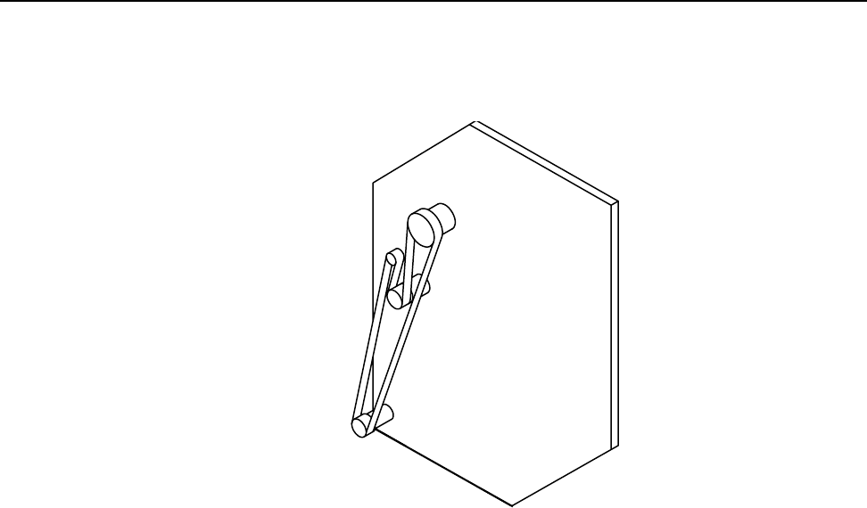
SECTION 6 Preventive Maintenance Guide
6–10 m®0855904enb 4/05
7.0 Drive Belts
Cimjet RFID has a single drive system:
• Tag web drive
Figure 6–3 Web Drive
The illustration shows the position of the stepper motor used and the
path of the timing belt.
To remove the web drive belt:
• Loosen all four screws on the stepper motor
• Remove the belt tension by rotating the eccentric cam; loosen
the eccentric's fixing screw on the FRONT of the Cimjet RFID
and rotate it using the tommy bar hole provided
• Remove the belt
Tag Web
Drive

SECTION 6 Preventive Maintenance Guide
0855904enb 4/05 m®6–11
To replace the web drive belt:
Feed the belt into position.
• Remember to tighten the motor screws before checking the belt
tension
• Do not put an excessive amount of tension on the belt as this
places undue strain on the motor bearings and will lead to
premature wear
There should be approximately 15mm (.591”) of movement in the
belt.

SECTION 6 Preventive Maintenance Guide
6–12 m®0855904enb 4/05
8.0 Maintaining the Compressed Air
The compressed air supply to the machine may contain moisture. A
water trap is provided in the main pressure regulator, and this will
require draining at regular intervals prior to machine use.
Carry out the following procedures:
• Check the water level in the water trap
• Place a suitable container under the water trap and drain by
pressing the valve pin in the base of the filter
• Check all of the air lines for leaks, security and condition
• Replace any defective air lines or connectors

Cimjet ® RFID
Operation/Service Manual
m
®
SECTION 7
Technical Information

SECTION 7 Technical Information
0855904enb 4/05 m®7–1
1.0 Power Configuration
Before installing the Cimjet RFID, ensure that the power supply is
correctly configured.
The power supply is configured by:
• Power connections to the Toroidal transformer located at the
rear of the machine
The Cimjet RFID is normally configured with the necessary power
connections and fuse fitted to suit customer requirements. If the
requirements change, the Cimjet RFID can be quickly reconfigured
by modifying the power connections.
1.1 Power Connector
A STASEI2 type connector is used for power. Single phase live,
neutral and earth connections are required.
• Pin 1 – Live
• Pin 2 – Neutral
• Ground pin – Earth
Ensure that the securing screw for the outer cover is always fitted.
The power requirements are 110 - 230V AC, Single phase rated at
375VA continuous, 750VA maximum at switch on.
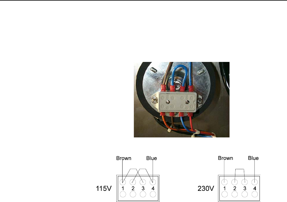
SECTION 7 Technical Information
7–2 m®0855904enb 4/05
1.2 Power Connections
The power connections are made at the terminal located at the rear
of the machine.The connection arrangement depends on the supply
voltage. The machine can be configured for 115V or 230V by adding
or removing the wire link provided. Connect the live (brown) wire,
neutral (blue) wire and appropriate link as shown.
Figure 7–1 Power Terminal
Figure 7–2 Power Connection Arrangement
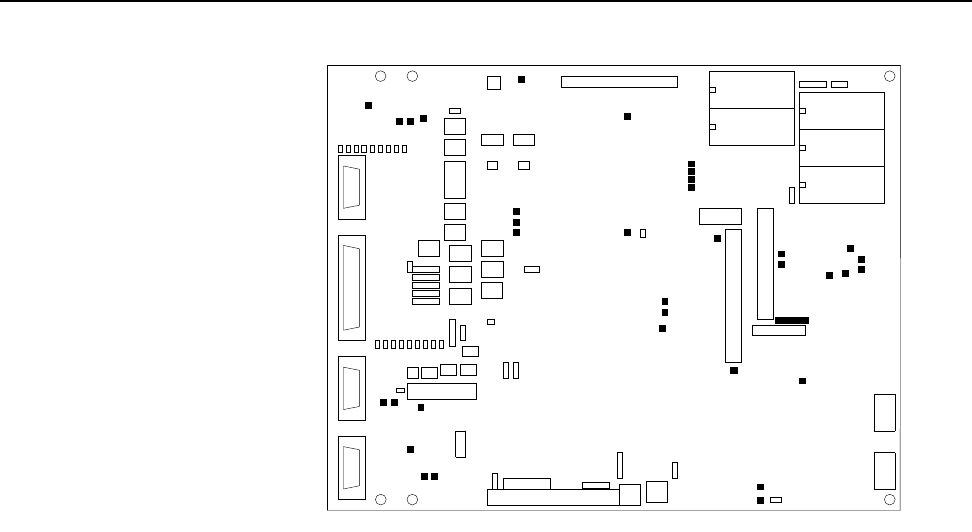
SECTION 7 Technical Information
0855904enb 4/05 m®7–3
2.0 The Cimjet RFID Main Processor Board
Figure 7–3 Cimjet RFID Main Processor Board
The main processor board is situated on the rear of the dispenser.
This board provides all the processing power, I/O buffering and
power for the feed control and general machine control for the
Cimjet RFID.
Details on the board main components are provided in the following
paragraphs:
• On-board Connectors
•LEDs
•Links
•Test Points
• Fuses
• Firmware and RAM
• Sensor Voltage Adjustment
X36
SW1
LD
8
X18
FR3
SW2
LK3
TP10
TP6
FR1
TP3
X25
TP20
X19
LD
9
TP
32
U12
TP7
TP27
X38
X27
X9
FR7
LK17
LK8
LD
15
TP5
TP34
TP
12
LD
4
LD21
RV2
X21
TP25
X7
LD
5
HI ROM
FR4
LD
10
LK9
LD
7
X30
TP11
X28
TP30
TB1
TP38
LK10
U16
LD
12
TP26
X3
X11
TP19
TP
33
F1
TP40
LK7
TP1
U5
LD
16
TP29
LK1
X20
X16
FR5
LD
11 IMAGE MEMORY
X14
TP9
LD
1
X29
X26
LK4
X12
TP17
TP14
X22
TP37
X5
LD
3
LK5
X1
LD
13
TP23
X13
TB2
TP4
IMAGE MEMORY
U10
DATABASE MEMORY
LD
6
LK15
X15
LD
17
FR2
X40
TP39
X4
TP22
TP
31
LO ROM
LK6
LD
2
LD20
TP18
X23
TP16
TP15
TP35
X35
TP24
X17
TP2
TB1, X29, X30 and X40 are on the other side of the Control
TP8
X24
U8
TP
13
LK16
LD
14
X8
FR6
FR8
LD
18
TP36
LD19
TP21
X6
RV1
TP28

SECTION 7 Technical Information
7–4 m®0855904enb 4/05
2.1 On-board Connectors
Table 7–1 On-board Connectors
Connector Function
TB1 Main Power Connector – 12-way
X1 Expansion I/O Connector
X2
X3 Head Lift Solenoid
X4 Totalizing Counter
1 – 24VSOL
2 – Output
X5
Gap Optic Drive
1 – Drive
2 – 0VA
3 – +5VA
4 – Sense
X8
Beacon Outputs
1 – Ready (N/O)
2 – Warning (N/O)
3 – Fault (N/C)
4 – 0VP
X9
Output #5 (N/C) – 2-way Molex
Connector
1 – Signal
2 – 0VP
X10
X11
Output #5 (N/O) – 2-way Molex
Connector
1 – Signal
2 – 0VP
X12 External I/O Connector – 25-way D-
type Socket
X13
Output #8 (N/O) – 2-way Molex
Connector
1 – Signal
2 – 0VP

SECTION 7 Technical Information
0855904enb 4/05 m®7–5
X14
Output #8 (N/C) – 2-way Molex
Connector
1 – Signal
2 – 0VP
X16 Operator Interface
X17
Output #9 (N/C) – 2-way Molex
Connector
1 – Signal
2 – 0VP
X18
Output #7 (N/O) – 2-way Molex
Connector
1 – Signal
2 – 0VP
X19
Reject Mechanism Solenoid
Output #9 (N/O) – 2-way Molex
Connector
1 – Signal
2 – 0VP
X20
Output #6 (N/O) – 2-way Molex
Connector
1 – Signal
2 – 0VP
X22
Head/Nip Open – 3-way Molex
Connector
1 – 24VS
2 – Signal
3 – 0VS
X23 External Sensor – 9-way D-type
Connector
X24 Applicator Input #3 – 2-way Molex
1 – 24VSNS
2 – Signal
X25
Low Paper – 3-way Molex Connector
1 – 24VS
2 – Signal
3 – 0VS
Table 7–1 On-board Connectors
Connector Function

SECTION 7 Technical Information
7–6 m®0855904enb 4/05
X26
Applicator Input #2 – 3-way Molex
1 – 24VS
2 – Signal
3 – 0VS
X27
Applicator Input #1 – 3-way Molex
1 – 24VS
2 – Signal
3 – 0VS
X28 External Host Comms Connector – 9-
way D-type Connector
X29 Web Motor Drive – 4-way Molex
X31 Internal Microprocessor Pins 1 - 36
X32 Internal Microprocessor Pins 37 - 72
X33 Internal Microprocessor Pins 73 - 108
X34 Internal Microprocessor Pins 109 -
144
X35 Internal JTAG Port
X36 Auxiliary 24V Output – 2-way
1 – 24VP
2 – 0VS
X37
X38 SPI Interface Connector – 20-way
X39
X40 Ethernet Option Connector – 12-way
Table 7–1 On-board Connectors
Connector Function

SECTION 7 Technical Information
0855904enb 4/05 m®7–7
2.2 Input and Output LEDs
Table 7–2 Input LEDs
Input LED Function
Main Processor Board
LD1 Feed and Apply Input
LD2 Spare External Input # 1
LD3 E-stop Monitor
LD4 Guards Monitor
LD5 Applicator Input # 3
Spare External Input # 2
LD6 Low Paper
LD7 Applicator Input # 1
LD8 Applicator Input # 2
LD9 Head/Nip Open

SECTION 7 Technical Information
7–8 m®0855904enb 4/05
Table 7–3 Output LEDs
Output LED Function
Main Processor Board
LD10 Fault
LD11 Warning
LD12 Reject
LD13 Busy
LD14 Applicator Specific
LD15 Applicator Specific
LD16 Applicator Specific
LD17 Applicator Specific
LD18 Applicator Specific

SECTION 7 Technical Information
0855904enb 4/05 m®7–9
2.3 Processor Board Links
Table 7–4 Processor Board Links
Link Number Function
LK1 Battery Link
LK2
LK3
Dump Valve Link (Default Link in)
Remove this link to enable remote
dump valve control via X12
connector
For links LK4 to LK8, configure respective outputs
for:
Link positions – 1-2,3-4 +24V
Link positions – 2-3,4-5 Volt-free operation (Default)
LK4 Ready Output – 5-way link
LK5 Fault Output – 5-way link
LK6 Warning Output – 5-way link
LK7 Reject Output – 5-way link
LK8 Spare Output #1 – 5-way link
LK9
Motor Safety Interlock (Default
Link in)
Remove link to enable remote
enable/disable of the motor
voltage via X12 connector
LK11 – LK14
LK 15
Boot ROM configuration (Default
A)
A = On Board ROM (U2 & U3)
B = Socketed ROM (U5 & U8)
LK16
Expansion ROM configuration for
U5/U8 (Default A)
A = Flash
B = EPROM

SECTION 7 Technical Information
7–10 m®0855904enb 4/05
LK17
Bootstrap link (Program upgrade
via RS232)
A = Default
B = Bootstrap enabled
Table 7–4 Processor Board Links
Link Number Function

SECTION 7 Technical Information
0855904enb 4/05 m®7–11
2.4 Test Points
WARNING: Only qualified personnel are allowed to use the
Test Points to check the board operation. All
precautions must be taken to prevent possible
injury and/or damage to the product.
Table 7–5 Test Points
Test Point Function
TP1 0VP
TP2 0V (Logic supply)
TP3 Reject Mechanism Solenoid –
PWM Switched Output
TP4 Reject Mechanism Solenoid – On/
Off Switched Output
TP5 Counter Out – Output for Optional
Hardware
TP7 Tag Gap – Analogue Sensor
Output
TP8 Tag Gap – 0V
TP10 0VP
TP11 24V – Regulated 24V Supply
TP14 35VU – Unregulated Supply
used to generate both 24V and 5V
Supplies
TP15 +5V Logic Supply
TP16 Paper Steps – Stepper Clock
Signal – Tag Web
TP17 Direction Paper – Stepper
Direction Signal – Tag Web
TP18 Paper Stepper Ref. – Stepper
Current Demand – Tag Web
TP22 0V – (Logic Supply)

SECTION 7 Technical Information
7–12 m®0855904enb 4/05
TP23 232/485 – Output for RS232/485
Selection for Comms Port (Active
High for RS232)
TP24 TX Data (TXD0) – Comms Port
RS232 Output Data
TP25 RX Data (RXD0) – Comms Port
RS232 Input Data
TP26 +VM – Motor Voltage (Nominally
+42V Unregulated)
TP27 0VM – Motor Voltage Ground
TP28 0VI – Isolated 5V Supply Ground
TP29 5VI – Isolated and Regulated 5V
Supply
TP35 SYSCLK – 20MHz Clock to PLD
Device
TP36 Development Use Only
TP37 Development Use Only
TP38 Development Use Only
TP39 Development Use Only
TP40 Ethernet Enable (Active Low)
Table 7–5 Test Points
Test Point Function

SECTION 7 Technical Information
0855904enb 4/05 m®7–13
2.5 Fuses
Table 7–6 Fuses
Fuse Function
FR2 24V I/O and Beacon Supplies –
1.35A
FR3 24V Solenoid Supply – 0.75A
FR4 24V SPI Supply – 0.75A
FR5 24V Sensors Supply – 0.75A
FR6 Motor/Reject Supply – 4A
FR7 5V Isolated Supply – 0.17A
FR8 5V and 24V Supplies – 5.0A

SECTION 7 Technical Information
7–14 m®0855904enb 4/05
2.6 Firmware and RAM
The Cimjet RFID board supports three different options for machine
control software. The software is stored in two ROMS. These will
either be Flash ROM or EPROM and will be tagged with a “P”
number indicating the software version. The devices will also have a
tag indicating HI or LOW.
CAUTION: These devices are sensitive to static, and care
should be taken not to touch the pins on the
external devices.
These options are as follows:
• On-board Internal Flash ROM
• External (Pluggable) Flash ROM
• External PROMs
These various options require that the appropriate links are set.
See previous pages in this section for the correct configuration.
The devices and the sockets both carry an indent or positioning
mark; these indents should be matched to ensure the devices are
inserted in the correct orientation. Inserting them in the wrong
orientation will damage them.
The on-board and external flash programs can be upgraded to the
latest version by downloading from a PC; the EPROM versions will
require new EPROMs to be fitted.
Contact your local MARKEM Business Center or Agent for details.

SECTION 7 Technical Information
0855904enb 4/05 m®7–15
2.7 Switch Settings and Potentiometers
SW1 Board Reset
Potentiometers RV1 and RV2
These are used to set the voltage levels for the Tag Gap sensor.
The default settings are characteristic of standard tags but may not
be appropriate for all applications.
The voltage settings can be viewed on the Engineer Mode
Diagnostics Screen, and the appropriate adjustments can be made
to the voltage potentiometer by passing a tag with backing web, or
backing web only in the Gap sensor.
The recomended settings are as follows:
RV1 Tag Sensor Calibration
• Tag and Backing Web <0.5V
• Web Only (Tag Gap) >1.5V, <2.5V
• Empty >4.0V
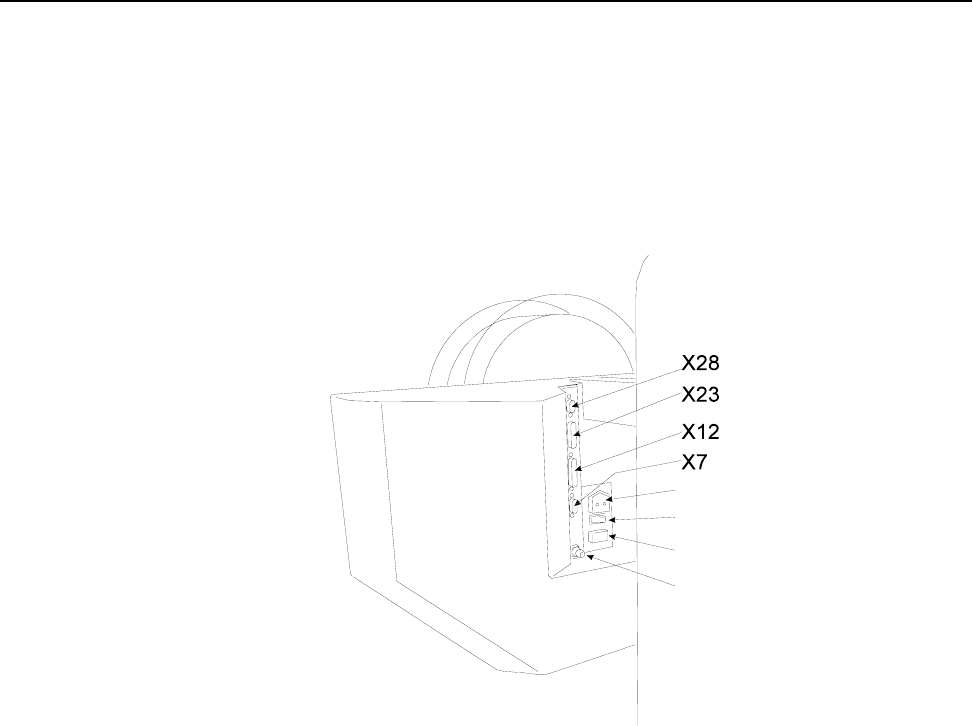
SECTION 7 Technical Information
7–16 m®0855904enb 4/05
3.0 External Connectors
Input and output connectors are provided on the rear of the Cimjet
RFID.
CAUTION: It is essential that the connector dust covers pro-
vided with the machine are fitted to all unused
connectors to protect against dust and prevent
possible static damage to internal components.
Power Connector
Power ON/OFF Switch
Fuse
Compressed Air Input
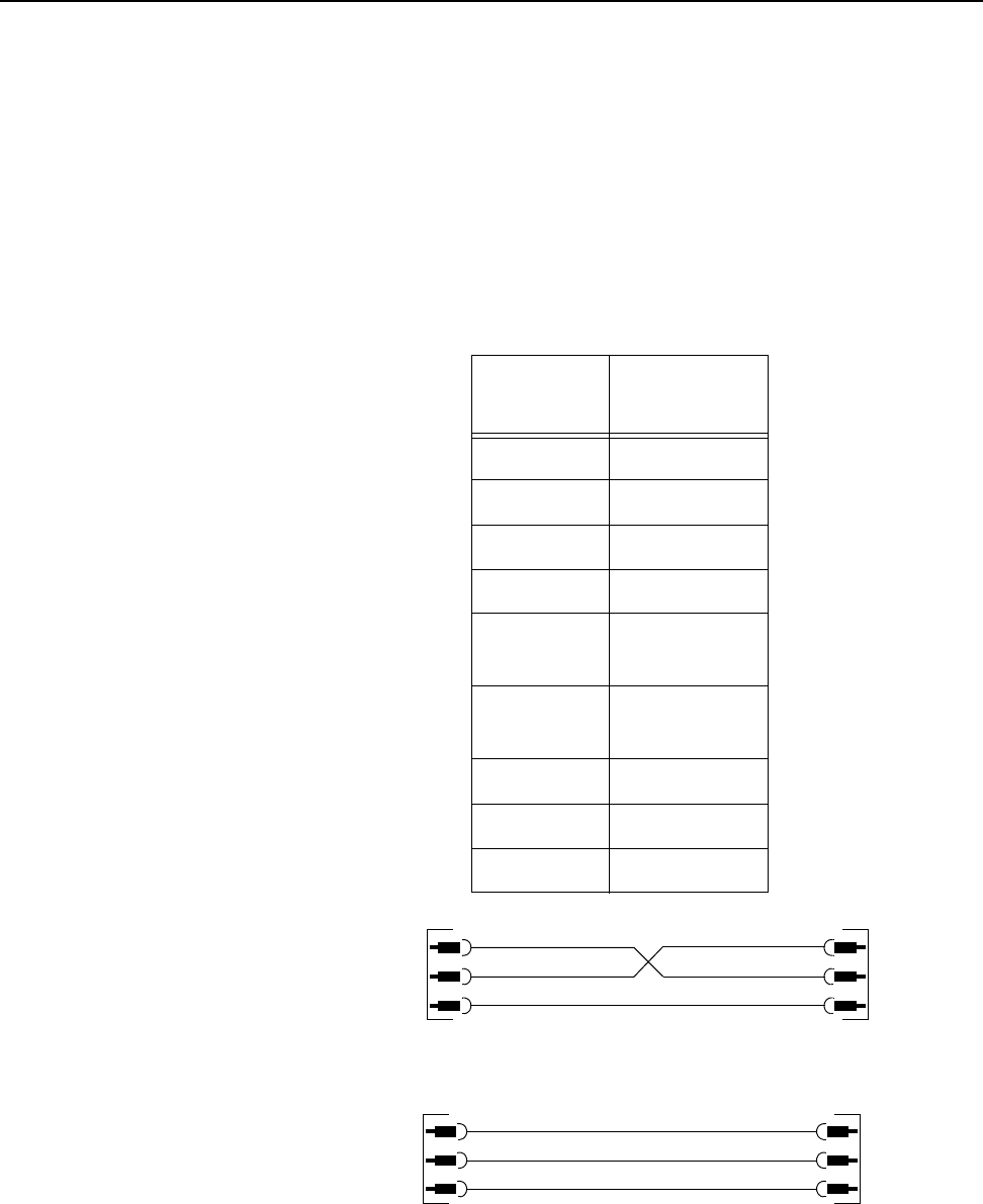
SECTION 7 Technical Information
0855904enb 4/05 m®7–17
3.1 X28 Communications (Comms)
This is a 9-pin miniature D-type connector.
The X28 port supports RS232 and RS485 comms.
It provides communication to CimControl, Host PC, Mainframe or
PLC and is also used for Emulation Mode.
Figure 7–4 shows suitable RS232 cables for connecting your PC to
the Cimjet RFID. For RS485 wiring details, please refer to Section
10 – Parts Illustrations and Schematics.
Figure 7–4 PC to Cimjet RFID - RS232 Cable
Table 7–7 Comms Port Connections
Pin
Number Description
1 TXD0/485+
2 RXD0/232
3 TXD0/232
4 RXD0/485-
50V
(Isolated)
6No
Connection
7 RXD0/485+
80V
9 TXD0/485-
2
3
5
2
3
5
2
3
5
2
3
7
9-WAY PORT CONNECTION
25-WAY PC PORT
MALE
9 W
MALE
9 W
MALE
9 W
MALE
25 W
CIMJET PC

SECTION 7 Technical Information
7–18 m®0855904enb 4/05
3.2 X23 External Sensor Connection
This is a 9-pin miniature D-type connector.
The X23 sensor port provides connection to external sensors, such
as the Feed and Apply sensors.
The wiring requirements depend on the type of applicator used.
The Inputs are designed to operate with PNP sensors or volt-free
contacts. If external voltage is used, it must not exceed 30VDC.
Where volt-free contact is used, the contact should be wired
between the input pin and one of the 24V supplies on the connector.
For example: Feed signal Pins 1 and 2
Table 7–8 External Sensor Connections
Pin
Number Description
1 + 24V
2 Feed Sensor Input
30V
4 + 24V
5 Laser Gate Input (LAS-G-IN)
Optional Serial/Laser Board
Required
60V
7 Product Gone Sensor
(Spare Input SP-EXT-IN1)
8 Apply Sensor
(Spare Input SP-EXT-IN2)
90V

SECTION 7 Technical Information
0855904enb 4/05 m®7–19
3.3 X12 External I/O
This is a 25-pin miniature D-type connector.
The X12 connector is used for additional machine control and
monitoring signals, such as fault and warning signals, which can be
used for controlling beacons or for linking to the conveyor control
system.
Machine outputs can be configured to operate as volt-free contacts
or as 24VDC outputs. The mode of operation for each output may
be configured individually. A link on the mother board is used to
select the operating mode (refer to Section 7, paragraph 2.3
Processor Board Links).
• The volt-free outputs can source up to 1 amp at a maximum of
30 VDC
• In 24V mode, the Cimjet can supply up to 1 amp total across all
the outputs using the 24V supply
A number of additional connections are provided:
Motor Safety
When LK9, on the mother board, is removed, the motor safety
connections on X12 must be connected. The relay or output used
must be capable of dealing with 35VDC at 3 amps.
Dump Valve Interlock
When LK3 on the processor board is removed, this allows the two
dump valve interlock connections on X12 to be used to control the
dump valve output. Dump valves are only used on applicators
requiring a hard-wired dump valve to make the machine safe.
The external contact must be capable of handling 0.25 amps at 24
VDC.
Safety Module Connections
The 24V, 0V, E-stop and guard connections allow an optional safety
module to be provided for applicators where the level of risk requires
a hard-wired safety circuit. The N/O or N/C state indicates the state
of the circuit when the Cimjet RFID is powered up and operating in a
fault/warning free condition.
Note: N/O = Normally Open, C = Common, N/C = Normally Closed

SECTION 7 Technical Information
7–20 m®0855904enb 4/05
* Pins valid when optional serial/laser board installed
Table 7–9 Safety Module Connections
Pin Number Description
Volt-free Mode +24V Mode
1 Ready (RDY) (N/O) Ready (+24V) (LK4)
2 Ready (C) 0V
3 Fault (N/O) Fault (+24V) (LK5)
4 Fault (C) 0V
5 Fault (N/C) Fault (+24V)
6 Warning (N/O) Warning (+24V)
(LK6)
7 Warning (C) 0V
8 Warning (N/C) Warning (+24V)
9 Reject (N/O) Reject (+24V) (LK7)
10 Reject (C) 0V
11 Busy (N/O) SPOUT (+24V) (LK8)
12 Busy (C) 0V
13* +5V
14* 0V
15 Motor Safety + (+42V) (LK9)
16 Motor Safety - (42V - SW)
17 Dump Valve Interlink (24V) (LK3)
18 Dump Valve Interlink (24V - SW)
19 +24V
20 E-stop (Monitor I/P Only)
21 Guards (Monitor I/P Only)
22 0VP
23* TXD2 (RS232 Optional)
24* RXD2 (RS232 Optional)
25* GND (RS232 GND)

SECTION 7 Technical Information
0855904enb 4/05 m®7–21
4.0 Status Output
The status output can be configured to inform an external control
system of various conditions.
• An example is when the Cimjet RFID has completed feeding the
last tag or when the Cimjet RFID has completed an apply cycle;
the status output can then be reset by one of the user options in
the restricted access menu, machine configure parameters.
• 24V Output (N/O) or (N/C) contacts switched by the Cimjet RFID
• Connections on X44 (N/O) or X45 (N/C) – 2-pin Molex
connectors on the serial/laser board
• Pin 1 – +24V
• Pin 2 – 0V
For further information on status signals, please refer to the
CimComms Protocol Documentation, which is obtainable from
MARKEM or can be downloaded from MARKEM.com:
http://www.markem.com/index.jsp

SECTION 7 Technical Information
7–22 m®0855904enb 4/05
5.0 Status Reset Input
In some cases, it is necessary to have secure interlocking of the
Cimjet RFID with external control systems. The Status Output is
used to do this.
For example, it may be necessary for the external control system to
know when the Cimjet RFID has finished feeding the last tag in
order for it to accept the next feed tag signal. The Status Output
can be configured to do this. This output can be reset by several
different means, one of which is by the Status Reset Input.
This input is normally switched by the external control system.
Note: This is only available if the optional serial/laser board is fitted.
Connections on X43 – 3-pin Molex connector on the serial/laser
board
• Pin 1 – 24V DC
• Pin 2 – Signal
• Pin 3 – 0V
Signal can either be volt-free, using pins 1 and 2, or a 24V signal
from an external source such as a PLC, using pins 2 and 3.
This option can be activated from the Restricted Access\Machine
Configure parameters.
For further information on status signals, please refer to the
CimComms Protocol Documentation, which is obtainable from
MARKEM or can be downloaded from MARKEM.com.
http://www.markem.com/index.jsp

SECTION 7 Technical Information
0855904enb 4/05 m®7–23
6.0 Display I/O
The Diagnostic Display I/O function allows the operator to monitor
the status of the machine inputs and to activate the machine outputs
for testing purposes.
These functions can be accessed from the Engineer Mode screen
under Diagnostics.
• Select ENGINEER MODE
• Select DIAGNOSTICS
The I/O screen can be extremely useful when fault finding.
A full description of the functionality of the inputs and outputs
follows:
ENGINEER
MODE
DATABASE PARAMETERS
DIAGNOSTICS MANUAL
TEST SET TAG
FEED OPTIC

SECTION 7 Technical Information
7–24 m®0855904enb 4/05
7.0 Inputs
The functionality of various sensors and other inputs can be tested
by viewing their status on the Engineer Mode - Diagnostic screen.
• Select Disp I/O from the Engineer Mode - Diagnostic screen
The inputs screen is displayed:
The status of Applicator Inputs depends on the type of applicator
fitted. The applicator inputs are listed in the individual applicator
sections, Table 7-10.
DISP I/O TIMINGS
INPUTS 1
FEED ON
NEXT PREVIOUS

SECTION 7 Technical Information
0855904enb 4/05 m®7–25
.
Table 7–10 Diagnostic Screen - Inputs
Input Description
Feed
Indicates the condition of the
Sensor signal to start the feed or
feed and apply sequence
Status: On/Off
Spare Input Applicator-specific
Spare Input Applicator-specific
Spare Input Applicator-specific
Apply
Indicates the condition of the
Sensor signal to start the apply
sequence
Status: On/Off
Low Web
Indicates the condition of the Low
Paper warning sensor
Status: On/Off
Spare Input Applicator-specific
Spare Input Applicator-specific
Nip Closed
Indicates the condition of the feeder
and Feed Roller Nip sensor.
Status: On/Off
Status Reset
Indicates the condition of the
Status Reset function; this can be
a signal from an external device,
such as a PLC
Status: On/Off
Tag Gap
Indicates the voltage levels from
the Tag Gap sensor; these levels
will change as tags or backing web
are present in the sensor
Status: 0V - 4.5V

SECTION 7 Technical Information
7–26 m®0855904enb 4/05
*Does not apply to Cimjet RFID
Serial Laser*
Chan 2
Database
Size Displays the size of database fitted,
such as 512K
Software
Version
Displays the current release of
firmware being used in the
machine, such as
P2850 - 11/07/01
Board
Revision Displays the type of processor
board fitted, such as REV D
Table 7–10 Diagnostic Screen - Inputs
Input Description

SECTION 7 Technical Information
0855904enb 4/05 m®7–27
8.0 Outputs
• Select Disp I/O from the Engineer Mode - Diagnostic screen
To select the Outputs screen:
• Press the soft key next to INPUTS
The Outputs screen is displayed:
The condition of the outputs can be changed by using the TOGGLE
soft key.
DISP I/O TIMINGS
INPUTS 1
FEED OFF
NEXT PREVIOUS
OUTPUTS TOGGLE
READY OFF
NEXT PREVIOUS
OUTPUTS TOGGLE
READY ON
NEXT PREVIOUS

SECTION 7 Technical Information
7–28 m®0855904enb 4/05
ASCII Comms connections
The ASCII Comms function can be initiated from a Transport
control PLC or other host system. In all cases, the RS232
connections are the same.
The ASCII Comms option should be selected in the Laser
parameters.
The ASCII Comms connections are the same as for a Wand
scanner; the distinction between the two options is made when
setting up the laser parameters.
The ASCII RS232 Comms are connected via the 25-way, external
I/O connector (X12) on the rear of the machine.
• Pin 23 – TXD2 (RS232 Optional)
• Pin 24 – RXD2 (RS232 Optional)
• Pin 25 – RS232 Ground
Table 7–11 Diagnostic Screen - Outputs
Output Description
Ready An input for the conveyor PLC or for a
Beacon lamp
Warning An input for the conveyor PLC or for a
Beacon lamp
Reject An input for the conveyor PLC or for a
Beacon lamp
Machine Busy An input for the conveyor PLC or for a
Beacon lamp
Spare Output Applicator-specific
Spare Output Applicator-specific
Spare Output Applicator-specific
Spare Output Applicator-specific
Spare Output Applicator-specific
Reject
Mechanism Activates the Reject Mechanism
Status Output
Status output is activated after a status
comms message has been sent; output
can be tested by activating the Toggle
soft key

SECTION 7 Technical Information
0855904enb 4/05 m®7–29
9.0 Pneumatics
9.1 Air Requirements
A compressed air supply is required by the Cimjet RFID to drive the
applicator module. This must be air at 6 Bar and should be: dry,
uncontaminated air, and not lubricated.
A filter regulator assembly is fitted to the base of the stand; this is
comprised of a manual isolation valve, a water trap, pressure
regulator, and dump valve. The air supply is via a 6mm or 8mm
flexible pipe.
9.2 Compressed Air Requirements
WARNING: Do not adjust the regulator pressure under any
circumstances. Doing so could make the Cimjet
RFID unsafe.
A filter regulator is provided as standard and includes:
• Isolation value (non-lockable)
• Pressure regulator
• Pressure indication dial (0-10 bar)
• Filter (micro mesh)
• Water trap
The unregulated supply goes to the Cimjet RFID dispenser.
The regulated supply goes to the applicator.
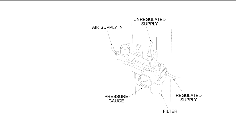
SECTION 7 Technical Information
7–30 m®0855904enb 4/05
Figure 7–5 Air Filter/Regulator Unit
A 6mm (.236”) push fitting is provided to accept flexible pipe.
The supply should be at 6.2 Bar (90psi). It should also be dry,
clean, and not lubricated.
The regulator unit provides:
• a regulated air supply for the applicator
(Plug on Cimjet RFID)
TO DISPENSER
TO APPLICATOR
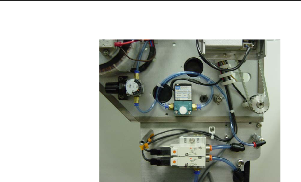
SECTION 7 Technical Information
0855904enb 4/05 m®7–31
The Tag Reject Mechanism has a separate air regulator which is
mounted inside the dispenser cover next to the solenoid valve that
operates it.
Figure 7–6 Air Regulator and Solenoid Valve for Tag Reject
Mechanism
The air pressure for the Tag Reject Mechanism does not normally
have to be adjusted and should be set to 3.5 to 4.0 Bar.

SECTION 7 Technical Information
7–32 m®0855904enb 4/05

Cimjet ® RFID
Operation/Service Manual
m
®
SECTION 8
Troubleshooting Guide

SECTION 8 Troubleshooting Guide
0855904enb 4/05 m®8–1
1.0 Error Messages in Auto Mode
If a fault occurs, the Cimjet RFID comes out of Auto Mode and the
error message is displayed. This includes a suggestion on how to
clear the fault. For example:
When Cimjet RFID is in error, the machine ready output is opened
and the fault output closes.
The following tables list the errors that can occur, together with the
remedial action required to rectify the fault. If the fault cannot be
cleared, refer to Section 7 – Technical Information for further
details, or seek qualified MARKEM technical assistance.
FAULT 03: NIP OPEN
CHECK NIP
THEN PRESS AUTO

SECTION 8 Troubleshooting Guide
8–2 m®0855904enb 4/05
2.0 Power-up Error Messages
These errors can be generated when the Cimjet RFID is powered
up. If the battery backed RAM is corrupt, one of the following
messages will be displayed:
Table 8–1 Power-up Error Messages
Message Indication/Action
Parameters
Lost
Setup parameters are corrupt
Check all setup parameters to
ensure correct operation
Memory
Lost
Parameter database has become
corrupt
Re-power the machine while
pressing the Enter and Exit keys at
the same time; this will clear any
corruption in the processor

SECTION 8 Troubleshooting Guide
0855904enb 4/05 m®8–3
3.0 Start-up Error Messages
Table 8–2 Start-up Error Messages
Message Action
Low Web Indicates that the tag supply is getting
low; this is only a visual warning and
does not stop Cimjet RFID operation
No Web
The tag gap sensor is not detecting tags.
If tags are loaded, check that the tags
are passing through the tag gap optic
sensor. If tags are present, reset the tag
gap optic from the Engineer Mode
Parameters
Nip Open Ensure that the nip roller has been
secured back in place
Missing Tag
The Cimjet RFID has detected that there
are tags missing from the web. This can
cause products to be untagged. Check
the tag stock for missing tags and
replace the reel if necessary.

SECTION 8 Troubleshooting Guide
8–4 m®0855904enb 4/05
4.0 Other Error Messages
You may see other errors, such as a CYLINDER FAULT, which are
associated with the applicator.
A complete list of all Cim* series machine error messages follows:
Table 8–3 Other Error Messages
Fault
Number Description/Action
01 NO WEB
CHECK TAG SENSOR THEN PRESS
AUTO
03 NIP OPEN
CHECK NIP THEN PRESS AUTO
04 CYLINDER FAILED TO RETURN
HOME
PRESS AUTO
05 MISSING TAG
CHECK TAG SUPPLY THEN PRESS
AUTO
06 MISSING GAP
CHECK TAG SENSOR THEN PRESS
AUTO
07 PACK SPACING
INCREASE SPACING THEN PRESS
AUTO
08 LOW AIR
CHECK AIR SUPPLY THEN PRESS
AUTO
09 E-STOP
RELEASE E-STOP THEN PRESS
RESET TO CLEAR
10 PAD NOT HOME
PUSH PAD HOME THEN PRESS
AUTO
11 GUARD OPEN
CLOSE GUARD THEN PRESS
RESET

SECTION 8 Troubleshooting Guide
0855904enb 4/05 m®8–5
12 NO PRODUCT DETECTED
PRESS AUTO
17
WARNING: ALLOCATION
COMPLETED SEND NEW
ALLOCATION OR PRESS AUTO TO
CLEAR
18 APPLICATOR ARM NOT HOME
PRESS AUTO
19 NO TAG HAS BEEN DETECTED ON
THE APPLICATOR
PRESS AUTO
20 PAD HAS FAILED TO RETURN
HOME
PRESS AUTO
22 CYLINDER 1 TIMED OUT
PRESS AUTO
23 CYLINDER 2 TIMED OUT
PRESS AUTO
24 PAD ROTATE TIMEOUT
PRESS AUTO
25 APPLICATOR OBSTRUCTED IN
CYCLE
PRESS AUTO
26 NO REJECT TAG AVAILABLE
PRESS AUTO
31 SENSOR MODE/CYCLE 1
EXPECTED/CYCLE 2 DETECTED.
PRESS AUTO
32 SENSOR MODE/CYCLE 2 NOT
DETECTED
PRESS AUTO
33 SENSOR MODE/PALLET PRESENT/
REMOVED IN CYCLE 1
PRESS AUTO
34 SENSOR MODE/CYCLE 2 INPUT
BEFORE EXPECTED
PRESS AUTO
Table 8–3 Other Error Messages

SECTION 8 Troubleshooting Guide
8–6 m®0855904enb 4/05
35 PLC MODE/CYCLE 2 DETECTED/
NO CYCLE 2 DEFINED
PRESS AUTO
36 HOST PRINT/CYCLE 2 DETECTED/
NO CYCLE 2 DEFINED
PRESS AUTO
Table 8–3 Other Error Messages

SECTION 8 Troubleshooting Guide
0855904enb 4/05 m®8–7
5.0 Communications Problems
If you cannot download information from your host PC, check the
following:
RS232 and RS485
• The correct cable is in use
• The cable is connected to the correct host port on the Cimjet
RFID
• Ensure that the cable has no broken wires or shorts between
wires
• Check that the communications parameters for the Cimjet RFID
and the host computer match
These are:
Communications Speed (Baud Rate)
This is set in Restricted Access Mode
Data Bits, Stop Bits and Parity
Cimjet RFID always uses 8 data bits, 1 stop bit and No parity
• The Cimjet RFID is set for the correct communications type,
such as RS232 or RS485
• The correct protocol is being used, such as (CIMCOMMS or
EMULATION) in restricted mode
• If a non-MARKEM host system is being used, ensure that it is
controlling TX-enable correctly and that there are no pauses in
the middle of message transmissions

SECTION 8 Troubleshooting Guide
8–8 m®0855904enb 4/05
6.0 Tag Feed Problems
Tag feed problems can be caused by several things such as:
• Machine being incorrectly webbed
• Drive belts slipping
• Stepper motor stalling
• Faulty gap sensor
• Incorrect parameter settings
If, for example, the stopping position was consistently wrong, the
most likely cause would be the parameter settings, such as the feed
distance.
If the stopping position is inconsistent, the cause is more likely to be
another possibility, such as the drive belt slipping or stepper motor
stalling.
6.1 Incorrect Tag Stopping Position
If the tag stopping position is incorrect after datum tags have been
fed and the stop position is consistent, check the following:
•FEED ADJUST parameter
•BACKFEED parameter (should always be set to 0 for Cimjet
RFID)
See the print parameter information in Section 4 – Restricted
Access Mode User Guide.
6.2 Erratic Tag Feeding
If the tags are feeding erratically, the gap optic settings may need
adjusting. To set the gap optic, carry out the following procedure:
• Press ENGINEER MODE
• Press SET TAGS OPTIC
The machine will now feed datum tags and will determine the
optimum sensor signal for the tag/web and web.
• Ensure that the Outer tag guide collars are set to the width of the
tag size being used, as this will stop the tag from tracking in and
out of the gap sensor
Note: Do not adjust the Inner collars as these are set to a fixed
distance from the baseplate.

SECTION 8 Troubleshooting Guide
0855904enb 4/05 m®8–9
6.3 Inconsistent Tag Stopping Position
6.3.1 If the Tag Stops in the Correct Position
If the tag stops in the correct position when datum tags are fed, but
the stop position is inconsistent after this, do the following:
• Check that the tag gap is not stopping in the Tag Gap Optic; this
may be purely coincidental because of the tag size, but it will
cause feed problems
• If this happens, move the sensor to the alternative position on
the baseplate and amend the Optic adjust parameter
accordingly
See the feed parameter information in Section 4 – Restricted
Access Mode User Guide.
• Drive problems, such as drive slippage, could also cause
variations in tag stop position
• Check that the nip roller is positioned in the center of the tag
• Check that the drive roller is clean
• Check that the dancer arm is operating
6.3.2 If the Tag Stops in an Inconsistent Position
If the tag stops in an inconsistent position after a datum feed, the
gap sensor threshold voltage may need to be adjusted.
Press ENGINEER Mode
Press DIAGNOSTICS
Scroll through DIAGNOSTICS to INPUTS
Scroll through INPUTS to LABEL GAP
Move the label up and down through the label gap sensor
• Record the voltage when the sensor is looking through the gap
• Record the voltage when the sensor is looking through the label
Calculate: (gap voltage + label voltage) ÷ 2 = gap threshold
voltage
To check the threshold voltage: In RESTRICTED SETUP,
• Press SET PARAMETER
• Press MACHINE OPTIONS
• Press MACHINE CONFIG
• Press NEXT to scroll through menu to GAP THRESHOLD
VOLTS
• Press CHANGE to update the threshold voltage value to the
calculated threshold voltage

SECTION 8 Troubleshooting Guide
8–10 m®0855904enb 4/05
7.0 No Driving of Tags
Check the following:
• Ensure that the clutches are operating correctly
• Check for broken drive belts
• If there is no motor voltage, check fuses and motor voltage test
point
• Ensure the external motor control link is in position - LK9 on the
main PCB
8.0 Motor Stalling
Tag feed problems could also be caused by the motor stalling.
The following problems may be the cause:
• The machine is webbed up incorrectly
• The brake band mechanism is too tight
• Incorrect drive belt tensions
• Incorrect clutch tensions
• Loose connections to the stepper motors
• Seized rollers or loose drive pulleys

Cimjet ® RFID
Operation/Service Manual
m
®
SECTION 9
Recommended Spares

SECTION 9 Recommended Spares
0855904enb 4/05 m®9–1
1.0 Recommended Spares
Preventive Maintenance Spares Kits are listed below. These are
followed by General Spares Kits.
1.1 Preventive Maintenance Spares Kits
Table 9–1 Roller Cleaning
Part No. Qty Description
5824648 100 Cleaning Pads
Table 9–2 Maintenance Parts – 100mm (3.94”)
Part No. Qty Description
33110BA 1 Felt Washer Kit
1116540 1 Nip Roller Assembly
33817BA 1 Two-sensor Assembly
5825198 1 Brake Band
5564717 1 100mm (3.94”) Wide Idler Roller
Assembly

SECTION 9 Recommended Spares
9–2 m®0855904enb 4/05
1.2 General Spares Kits
1.3 Left-hand Change Parts
Table 9–3 Basic Spares Dispenser Parts
Part No. Qty Description
31A104A 1 Tag Gap Sensor
5943412 1 Nip Latch Knob
31A58A 1 Nip Sensor
B03876AA 1 Low Web Sensor
B04297AA 1 Spare Main Fuse (T5A)
32621BB 1 Operator Panel Assembly
35146BA 1 LCD Display Assembly
5564342 1 Solenoid Assembly
Table 9–4 Left-hand Change Parts
Part No. Description
B05281AA 452-906 Blank Insert
B03636AA 453-886 Screwlock 8mm 4
B00215AA Fastening M5 x 10mm Cap
B00216AA M3 Plain Washer
B00217AA M3 Shakeproof Washer
B001171AA M3 Full Nut
B05088AA M3 Ext Star Lock W’R RS
B03697AA M3 x 20 Skt Set Screw
5824954 CIM300 LH Cover Assembly
5710372 LH Outside/inside Wound
5364271 D Connector Strip LH
5710264 Ident. Label LH

Cimjet ® RFID
Operation/Service Manual
m
®
Section 10
Parts Illustrations and
Electrical Schematics