MEIAN Technology MC-535R Wireless digital PIR detector User Manual
Shenzhen Meian Technology Co.,Ltd . Wireless digital PIR detector
User Manual
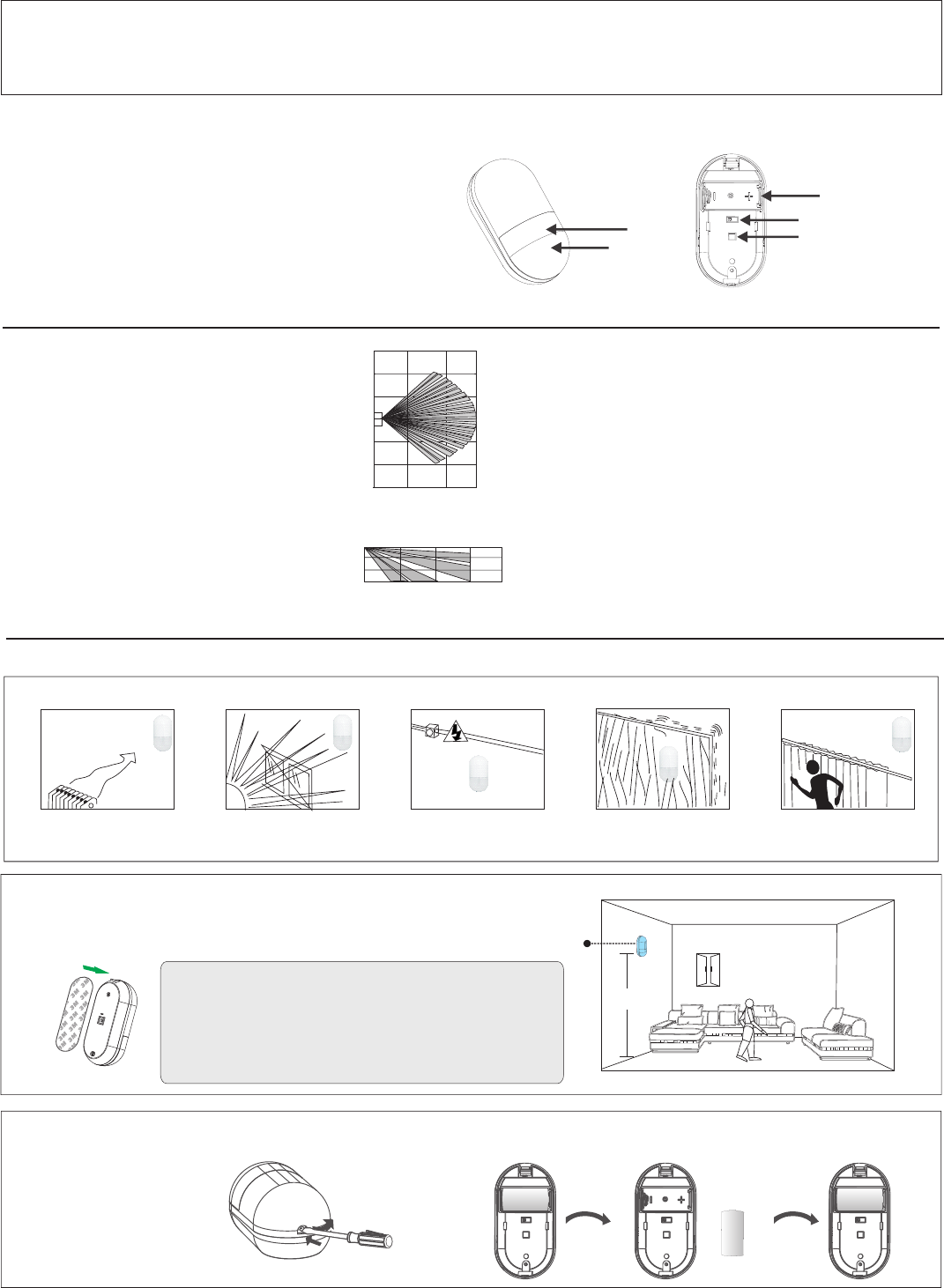
Installation:
①wide-angle: 12M * 12M detection angle of 110 degrees
②flat curtain: 12M * 2M detection angle of 3 degrees
③ceiling curtain: 6M * 1M detection angle of 3 degrees
Installation height
Operation condition:
Operation temperature:-10℃~60℃﹤95%RH
Storage temperature:20℃ ~60℃(4℉ ~140℉)
Size::86(L)*45(W)*36(H)mm
④ : 2~2.3M
3.Installation
3.1 Notes
Don't face cold or
heat directly
Don't face the sun
-shine directly
Don't install near
electric cables
Don't install on a
unstable base Don't face metal wall
Wall mounting wide
angle lens view
0
3m
3m
6m
6m
9m
9m
12m
8m
4m
0
Side view
2.3m
1.5m
0.6m
12m
8m
4m
7.5
2316,
5
2
,
,
,
8,
0,,
XXX
1.Introduction
X
3.2 Installation location
P/N:20170428A01
X
3.3 Change battery:
2~2.3m
Detector
Use double-sided adhesive to install the detector 2 to 2.3 meters
from the ground, pay attention to the installation of PIR down.
A, with a word screwdriver
light top groove, pull out the
bottom cover, remove the
bottom cover. +
+
-
B, remove the old battery, according to the marked polarity of the
battery correctly into the battery.
Fig.1 Appearance Fig.2 Internal Structure
PIR
LED Tamper switch
Battery container
DIP switch
MC-535R is a PIR intruder detector for indoor use.It adopts
precision cylindrical FRESNEL lens, can effectively improve
energy saving, with high sensitivity and free of false alarm. By
using advanced patented software, it can identify the real
intruder and other interference factor which may result in false
alarm. Pulse counting can be adjustable. It is widely use in
various indoor applications, Built-in big capacity lithium
battery, power-save mode.Its working life is up to 2 years or
above.
2.Specifications
Model:MC-535R
Maximum detection distance: 12m/25
Emitting distance: 120m (in the open area)
Infrared distance:
Working voltage: DC3V, 1*CR123A lithium battery
Alarm current: <20mA
Quiescent Current: 16µA~17µA
Infrared section (as shown at right)
Optical lens data sheet
Infrared area: 12 × 4 (typical)
Maximum coverage: 12m * 12m (39 * 39 feet) / 90 °
Emitting distance : 433MHz
Alarm indication: The LED indicator is on for 2~3 seconds.
℃
12m
Installation can choose to install wide-angle, flat
curtain, ceiling curtain three ways, different installation
methods corresponding to the installation height and
detection angle is different (see "2, specifications and
technical parameters").
-1-
Wireless digital PIR detector User Manual
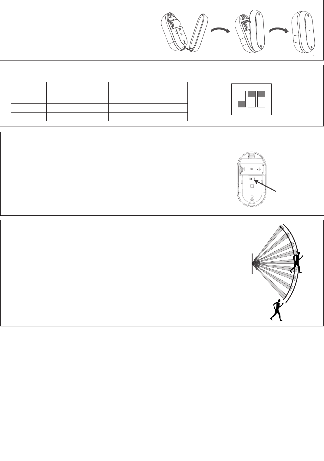
①Set the detector as test mode to proceed walk-test.
②Walk accross the far edge of coverage area at the speed of 1step/second
(about 0.75m/s). The LED will flash for seconds then alarm(see the right figure).
③Do walk-test in opposite direction to confirm the boundary of both sides.Make
sure the detection centre pointing to the centre of protected area.
④Make sure the detection centre at the proper place,should properly adjust the
detection area if you can not get an ideal detection area.
⑤After adjust the detection angle, should re-do walk test as above.
6. Walking test in coverage area:
7.Customer Service
⑥After passing the test, be sure to set the alarm delay to 5 minutes mode, otherwise it will
affect the battery life。
For any help please contact with our company and you could visit our website for more information
5. Coding method between detector and panel:
Coding setting:
①Set the detector as normal mode, place the battery and LED will flash
seconds,set the panel as coding mode(panel coding setting pls refer
to panel manual), within 3 seconds when press the confirm key of the panel
Wave hand near the front side of detector, it will send a alarm signal
to the panel, if the panel sounds a response then code successfully.
②Enter the address number to code with panel,set the panel as manual coding
mode and enter the 9-digit address number,this method is much better.
C, the side of the shell with a battery up one end, the bottom cover
with a button at one end down the face of the shell to close and
pull the bottom cover into the face shell.
Tamper switch
4.DIP switch function description
123
ON KE
1
2
3
OFF ON
Low sensitivity
High sensitivity(default)
Alarm delay 5 minutes(default)
LED is on(default)
LED is off
Switch serial
number
Alarm delay 5 second
-2-
Changes or modifications not expressly approved by the party responsible for compliance could void the user's authority
to operate the equipment.
This equipment has been tested and found to comply with the limits for a Class B digital device, pursuant to Part 15 of the FCC Rules.
These limits are designed to provide reasonable protection against harmful interference in a residential installation. This equipment
generates uses and can radiate radio frequency energy and, if not installed and used in accordance with the instructions, may cause
harmful interference to radio communications.
However, there is no guarantee that interference will not occur in a particular installation. If this equipment does cause harmful interference
to radio or television reception, which can be determined by turning the equipment off and on, the user is encouraged to try to correct the
interference by one or more of the following measures:
-- Reorient or relocate the receiving antenna.
-- Increase the separation between the equipment and receiver.
-- Connect the equipment into an outlet on a circuit different from that to which the receiver is connected.
-- Consult the dealer or an experienced radio/TV technician for help .
FCC WARNING
This device complies with part 15 of the FCC rules. Operation is subject to the following two conditions:
(1) this device may not cause harmful interference, and
(2) this device must accept any interference received, including interference that may cause undesired operation.