MEIAN Technology ST-IIIB ALARM CONTROL PANEL User Manual
Shenzhen Meian Technology Co.,Ltd . ALARM CONTROL PANEL
User Manual
P/N 20130320-1
ST-IIIB user manual

Dear customer:
Congratulations on purchasing you new security systeman thank
you for the confidence you have shown in us.You have chosena high
-quality.
Product that has been produced,tested and packed wthegreatest
care.Please familiarize yourself with these instructions before atte
mpting operation will only been sure if it is fitted properly.We hope your
new security system will bring you lasting pleasure.
Brief
产品 手册
User manual

Content
产品 手册
User manual
Chapter I Introduction 1
Chapter 2 Installation and Connection 4
2.1 Installation 4
2.2 Connection(N.O. N.C) 4
2.3 Install wired detector 4
2.4 Intall wereless detector 5
Chapter 3 Keybad and Operation 5
3.1 About panel 5
3.2 Basic operation 7
3.5 Alarm procedure 10
Chapter IV Voice alarm receiving 11
and GSM control
4.1 Remote phone control 11
4.2 Alarm receiving phone operation 11
4.3 GSM remote operation 12
4.4 GSM alarm receiving 12
4.5 GSM control via SMS 12
Chapter IV Voice alarm receiving and GSM control 13
5.1 Set system clock 13
5.2 Set user password 13
5.3 Set voice phone 13
Chapter VI System Setting 14
6.1 Set password 14
6.2 Set CMS number 15
3.3 Flashes when phone line cut 7
3.4 Host arm and disarm 8
6.3 Set voice phone 16
6.4 Set system options 17
6.4.1 Set system clock 17

产品 手册
User manual
6.4.2 Set entry delay 18
6.4.3 Set exit delay 18
6.4.4 Set siren time 18
6.4.5 Set ring times 18
6.4.6 Set detector loss inspection 19
6.4.7 Set arm/disarm tone 19
6.4.8 Set arm/disarm report 20
6.4.9 Set others 2 0
6.4.9.1Set emergency alarm siren type 20
6.4.9.2 Ac off inspection time setting 21
6.4.9.3 Magnetic contact inspection 21
6.4.9.4 Check wireless detector tamper 21
6.4.9.5 Set force arm 2 1
6.4.9.7 Set zone alrm times 2 2
6.4.9.8 Set listen-in time 2 2
6.4.9.9 Set AC off remind 23
6.5 Manage wireless device 23
6.5.1 Set remote control 2 3
6.5.1.1 Enroll remote control 2 3
6.5.1.2 Enter remote control code 2 4
6.5.1.3 Delte remote control 2 4
6.5.2 Set detector 2 4
6.5.2.1 Detector coding 2 4
6.5.2.2 Enter detector code 2 5
6.5.2.3 Delete detector 25
6.5.3 Set appliance switch 2 5
6.5.3.1 Enroll appliance switch 2 5
6.5.3.2 Delete appliance switch 26
6.5.4 Enroll wireless siren 2 6
6.5.4.1 Enroll wireless siren 2 6
6.5.4.2 Delete wireless siren 2 6
6.6.5 Set door bell 2 7
6.5.5.1Enroll doorbell 27
6.5.5.2 Delete doorbell 27
6.4.9.6 Set telehpone line disconnect remind 22

产品 手册
User manual
6.6.1 Set zone attribution 28
6.6.2 Set zone siren type 28
6.6.3 Set wired zone loop type 28
29
6.6.4 Set wired zone response speed
6.6.5 Set related zone 29
6.7 System maintance 30
6.7.1 Set timing operation 31
6.7.2 Recording 31
6.7.3 Play recording 31
6.7.4 Set programmable output port 31
6.7.6 Restore to factory default 32
6.7.5 Delete system events 32
6.8 Set GSM module 32
6.9 Advanced setting options 34
6.9.2 Set sever IP address 35
6.9.1 GPRS enable and disable 35
6.9.3 Set sever port 36
6.9.4 Set user ID 36
6.9.5 Set user password 36
6.9.6 GSM SMS language 36
6.9.7 Delay zone tone source options 37
6.9.8 Handshake tone input signal intensity 37
6.9.9 DTMF output signal intensity 37
6.9.10 Set LCD standby brightness 37
6.9.11 Alarm event retain time 38
Chapter VII technical specification 39
7.1 General data 39
7.2 Physical performance 39
Chapter VIII maintenance 40
8.1 Regular test 40
8.2 The cleanliness of control main machine 40
Chapter VX limitation of the products 40

I Alarm mode: with PSTN and GSM network alarm, GSM network with
GPRS function(GPRS function is for China market only), remote arm and
disarm panel through CMS or SMS CID protocol, SMS notification, the
priority of PSTN and GSM network is Optional.
With a new large-screen, full-touch buttons, LCD graphic display steps,
work status,Alarm process easy and intuitive.
The full English voice prompting operation: all local or remote operation,
alarm information, event log view.
4
、
2、
3、
、GSM-hook and voice telephone with intercom function.
5、All alarm information can be programmed for the following settings:
0 does not send any information
1,Send only SMS 2,Only call users 3,SMS + call user 4, CMS only
5 ,CMS + SMS. 6,CMS + call user 7. CMS + SMS + call user
6、Sleep mode: Under sleep mode, all the lights, backlight, voice and
remind tone are disabled.
7、Alarm panel under idle status is equivalent to a cellphone, you can call
through the GSM network for balance inquiries
8、The associated zone: 4 groups associated zone, three kinds of
association patterns, can effectively reduce false alarm or for other
functions.
9、PGM output: With a programmed output port, followed by five kinds of
alarm events output.
10、The doorbell Audio Optional:
1. Ding Dong 2 Welcome 3. Recording 4. Dee-Dee~
11、Remote phone operation: dialing by telephone offsite, after password
verification, you can arm, disarm, listen-in premise, system status query
and electrical switches controls and other operations.
12、Voice Alarm: When panel alarm, it will automatically dial the preset user
phone numbers to report alarm information then you can remote control
the panel after enter user passwords.
1
产品 手册
User manual
Chapter I Introduction
1.1 Function Introduction

22、
23、For CMS
Password access management: the panel has one administrator
password 16 user password, The administrator password primarily for
system administrators to set up the alarm system; The user passwords
for users in the day-to-day use such arm/ disarm,remote operation. The
administrator password, user password can be freely modified.
networking alarm, depending on the number of users, the user
can set four, six or eight user codes(account number).
2
14、8 wired zones, User can set the circuit type and speed of
response, support N.O, N.C.
15、Enable enroll total 8 wireless remote,8 electronic switch,1 pc of wirele-
ss doorbell and Unlimited for quantity of one way wireless siren.
16、 Follow me phone #,two for CMS,four for private alarm receiving.
17、Status inspection function:Enable record and inquiry 120 alarm event
messages.Like the time when happens anti-tam per alarm,detector alarm,
tel-line off,arm,disarm,system setting,battery low volt age etc.And also
can inquiry the zone number and alarm type.
18、
、
、
、
Timing arm and disarm: 4 sets of timing arm and disarm time.
19 Electrical switches control: User can remote switch on/off via phone or
SMS, also can be controlled manually through the local alarm panel.
20 Zone programmable: factory preset for each zone type. Users
can modify all the zone type according to the actual needs .
21 Clock: Built-in full automatic calendar clock, set to local time
consistent
产品 手册
User manual
13、Wireless zones, each wireless zone can automatically learn the codes
or be coded manually via the keyboard.
24 Zone type identification:After an alarm is triggered, the alarm zone
number displayed on the LCD screen of the panel, also can send the
detailed report to CMS which includes alarm locations and zone types.
、
25、Al-proof function:If try to cut off the wire between wered detector and
panel or cut off the tel line which.

3
产品 手册
User manual
26、
、
、
、
、
、
、
The tampering alarm: cut the cable between wired detectors and the
will trigger larm, the telephone line cut will autom atically trigger siren alarm.
When someone deliberately dismantled the panel, it will alarm when
triggering tamper switch at the back of the panel.
27 Timing arm/disarm:Enable set 4 group time arm/disarm time.
28 CMS communications test: The panel will send a message to CMS at the
pre-set time interval to inspect the communicaiton if normal.
29 Siren options:Built-in siren, external wired siren, Wirelss siren. All sirens
can be programmed as enabled/disbale when alarms.
30 The voice speaker volume adjustment: adjust the volume by a rotary
switch on the panel.
31 Wireless repeater function:can extend the distance between the detector
and the panel by adding a wireless repeater of our company.
32 The wireless detector low battery prompted:Detectors will send status
report to the panel every 1-3 hours, the corresponding zone number and
the battery voltage symbol will be displayed on the LCD screen and also
will report to CMS.
panel
2.1
1.
2.
3.
Installation
Fix the bracket to the wall and hang the pane to the bracket
The large metal objects can not be placed around the panel, so as not to
affect the wireless signal.
Make sure to place the panel within the wireless range of all wireless
accessoris and pay attention to the hidden
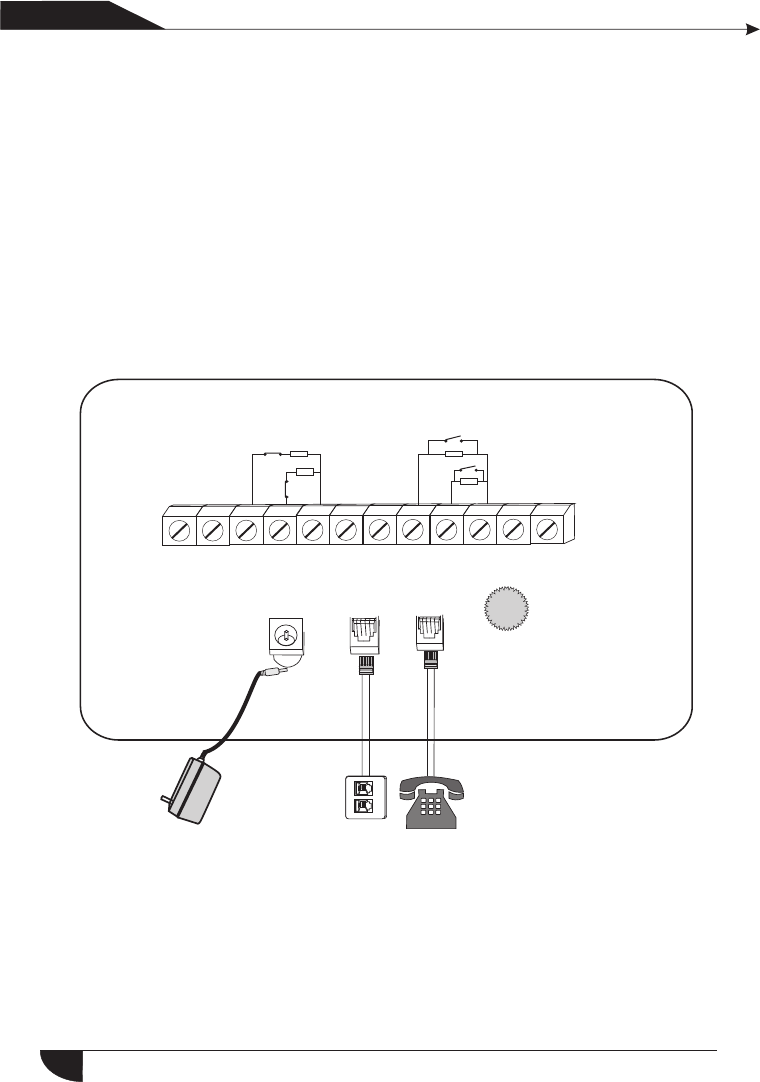
2.2 Connection(N.O. N.C)
LINE TELL
DC15V/2A
Power
PGM GND Z33 Z34 GND Z35 Z36 Z37 Z38 GND Z39 Z40
NO
NC 10K
10K
10K
10K
NC
NO
Here only i ntroduce the zone 33, 34, 37 , 38. The other zones pl ease
2.3 Install wired detector
2.3.1The wired zones is disabled factory default. when to use wired zones
please enable the zones firstly.When wired zones is in trouble, the
panel will voice prompt "operation fails, Zone trouble” if users try
4
产品 手册
User manual
N.ON.C
As pictures
Chapter 2 Installation and Connection
Voice volume
knobs
refer to the above.
The control pane can power 15V, 100mA to detectors. The max curent
is 100mA. Do not exceed 100mA, otherwise please use extra power
supply.
2.3.2
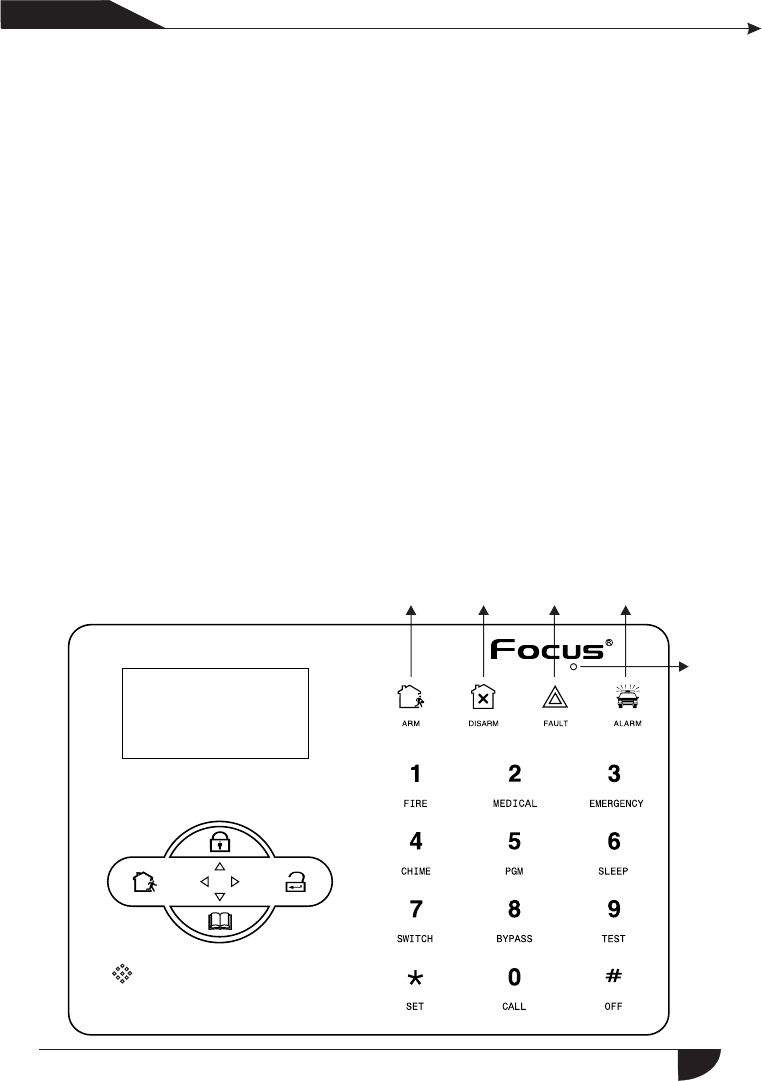
3.1 About panel
5
产品 手册
User manual
To arm the panel. The zone number will be also display on the LCD
screen. At this time arm system is not allowed unless you force arm.
2.4 Intall wereless detector
2.4.1 As the detector`s manual says,install coded detector in the area
from the control panel.Please test and make sure detector can work with
control panel normally.
2.4.2 Wireless repeater function:when wireless detector is too far from the
panel or some occluders between panel and detector which disable the
panel receivethe signal from wireless detector.Now you can choose our
made wireless repeater to achieve wireless signal relay trans mitting.
150m
Arm Disarm Alarm
LCD screen
Fault
Chapter 3 Keybad and Operation
Stay/on turn key
Intercom/monitor hole
Protection
/return button
Event query
/under turn key
Key machine
A light hole
Set the
keys
Enter
key

Arm led: Light on under armed status, Light flashes under stay status.
Disarm led: Light on under disarmed status
Trouble led: Light on when with zone trouble. Light flashes when AC cut.
Alarm led: Light flashes when alarm.
1
1
1
2
1
1
1
1
1
1
1
3
4
5
6
8
9
10
:Press 3 seconds to enter or exit sleep mode.
7
Bypass zone: bypassed zones means zones disabled. The bypass will be
restored when users disarm systems under home armed or armed status.
Siren test: to test if siren working normal
Walk test: to test if the detectors are working normally with the panel and alarm
产品手册
User manual
:Press 3 seconds to tirgger fire alarm
:Press 3 seconds for medical help
:Press 3 seconds for SOS
:Press 3 seconds then enter user code to enable or disable delay
zone doorbell(Refer to page 36)
:Press 3 seconds then enter user code to enable or disable PGM
output(refer to page 30)
:Press 3 seconds to make phone call through GSM, the longest
talk time is 240 seconds. the call will be interrupted when alarm
occurs.
:Press 3 seconds then enter user code to proceed normal testing,
siren testing and walk testing.
:Press 3 seconds then enter user code to bypass zones or
activate zones.
:Press 3 seconds then enter user code to enable or disable
eletrical switch.
Sleep mode: all led indicators, backlight, voice, remind tone will be disabled
under sleep mode, The panel will exit sleep mode automatically when users
enter system setting or when alarm occurs.
6
Communication test: To test the communication between the panel and the
CMS if normal
7
产品手册
User manual
3.2 Basic operation
Factory default
Adminitrator password: 012345
16 User passwords, NO. 01 factory default is 1234. No. 02-16 of the user
password is blank and can not enter the user setting untill user set the
password.
Home arm: Home arm key
Arm: Arm key
Event log: inquiry key
Shutdown operation: AC power-off state ( press and hold for more than 3
seconds) + user password [1234]+
Disarm: User password[1234]+DISARM
Enter system setting: press and hold for more than 3 seconds+
adminstrator password [012345]+
Enter user setting: Press and hold for more than 3 seconds+ user NO.
(01) +user password(1234)+
Zone inspection: Not insepct wired zones within one minutes of panel
power up
Password reset: Enter 000000 to enter system setting menu within one
minute of panel power up.
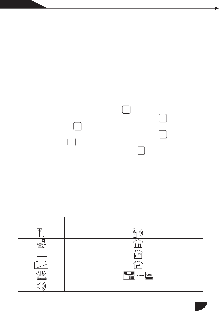
3.3 Flashes when phone line cut. Light on when phone line
is normal.
Icon Meaning
Detector low battery
Alarm
GSM is enabled
Left behind
Disarm
Arm
Enable GPRS
+_
G
Voice prompts
GSM signal strength
Telephone
line
PANEL battery
low
Icon Meaning
#
#
*
#
*
#
Zone 5 alarm
Zone 5 trouble
Zone 5 bypass
Zone 5 detector lost
Zone 5 low battery
The alarm zone number will still be displayed on LCD screen after first disarm
when alarm accurs, returned to normal screen display only users disarm twice.
Flashes when phone line cut. Light on when phone line is normal.
Flashes when GSM not ready, Light on when GSM is normal.
Flashes when GPRS disconnected with CMS. Light on when GPRS is
connected well with CMS.
Flashes under sleep mode. Light on uder normal working mode.
3.4 Host arm and disarm
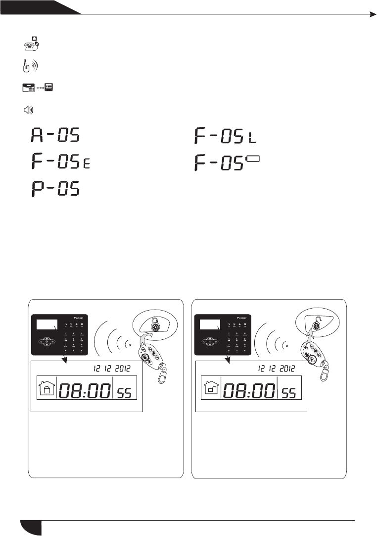
☆ Arm
☆ Disarm
YDM YDM
Press the key for arm away on remote
or the keypad,then you hear"system
armed,please exit the protection area"
there will be “Dee-dee”sound to
confirm the system is armed
successfully.
Press the disarm key on the remote or
enter your user password on the
keypad,then you will hear"dee"and
voice"system disarmed",then you have
disarm successfully.
~DI~DI~ ~DI~DI~
产品 手册
User manual
8
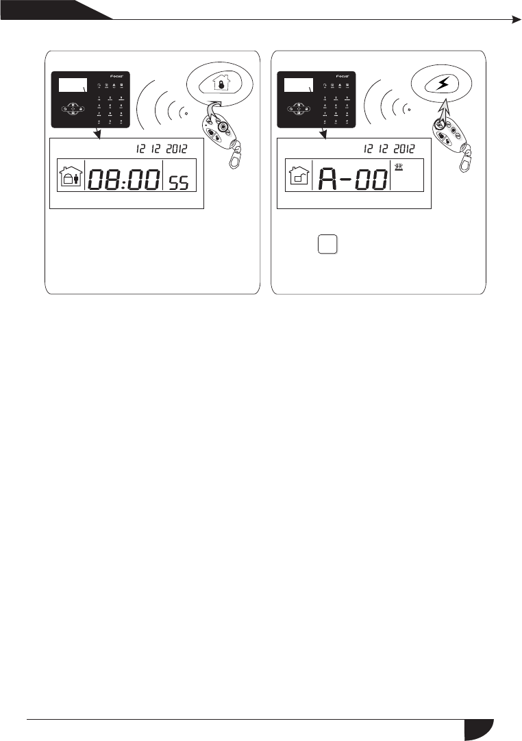
☆ Panic
☆ Home Arm
YDM YDM
产品 手册
User manual
Press the key for home arm on the
remote or "HOME"key on the keypad,
then you will hear "system stay"
And it display home arm icon on the
LCD screen.
Press the panic button on remoter,or
press" "key on panel for 3
seconds.
~DI~DI~ ~DI~DI~
9
The codes of arm/disarm via different ways:
Arm/disarm via keyfobs: 1-8 keyfobs----#40-47
Arm/disarm via user codes: 1-16 user codes---#01-16
Arm/disarm via phone call: 1-4 user phone number---#60-63
Arm/disarm via CMS: #97
Arm/disarm via home arm key or arm key in panel: #98
Auto arm/dsiarm via auto timer or key zone: #99
3
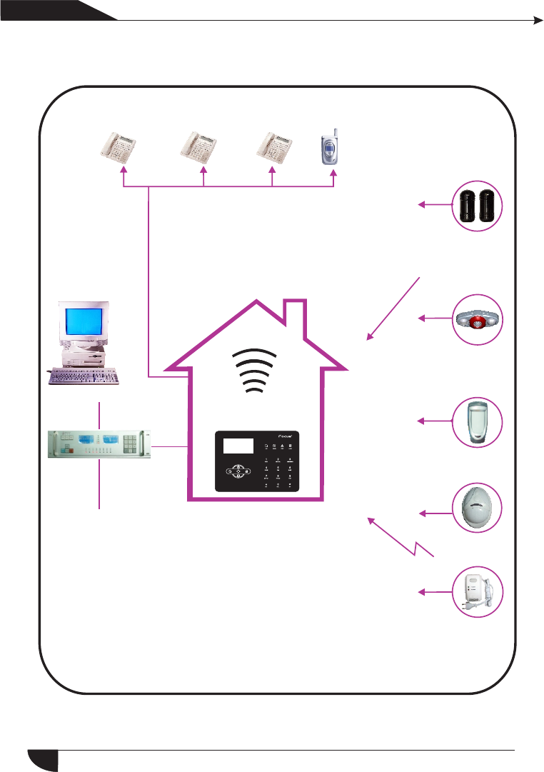
3.5 Alarm procedure
产品 手册
User manual
Tele Telephone telephone Cell phone
1st 2nd 3rd 4th
3.The panel will dial 1-4 telephone numbers
as preset.If more than 4 numbers,the panel will
start with second telephone number, then 3,4...
Wired
Alarm situation found,
start to send message
1.The detector activated
send alarm infor
mation to alarming
center.
Alarm software
CMS
110 alarm center
Wireless
2.The panel use Ademco Contact ID to send
alarm information to alarming center.
If the panel got confirmation from center,
then alarm successfully.Otherwise, the panel
will repeat alarm.The alarm information will
be display and reslove by the alarm center computer
software.
10
1 2 3
45
1 1
34
1
11
2
1 2
3
Chapter IV Voice alarm receiving
and GSM control
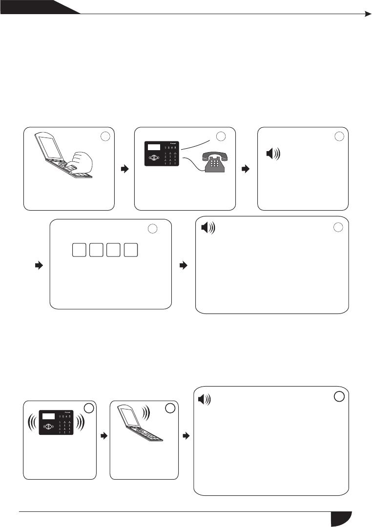
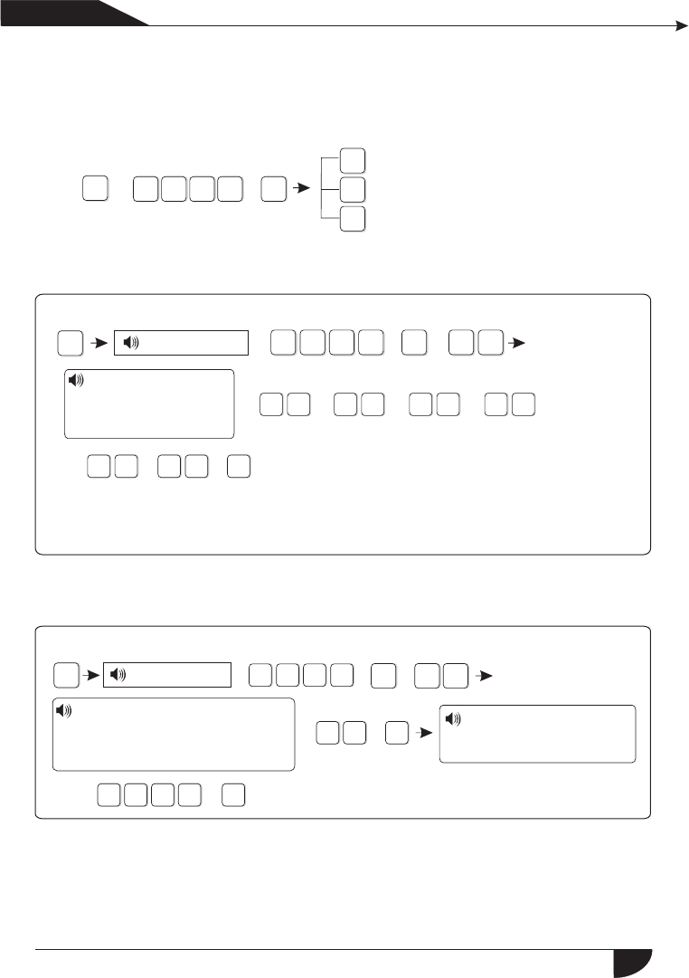
4.1 Remote phone control
User can remote control the system by phone call, after the preset ringing
times then panel will off hook the phone then enter the 4 digit user codes
according to voice prompting and operate as per the voice prompting.
User call landline
phones
The phone rings is 7
times, after 7 times ring,
the panel will off-hook
automatically.
Please enter
password
Then enter user code according
to voice prompting( the factory
default user code is 1234)
Press 1 to arm system
Press 2 to disarm system
Press 3 to Stay arm
Press 4 to check system status
Press 5 to appliance switch control
Press 6 to control programmable
output port
Press 0 to Disconnect
4.2 Alarm receiving phone operation
When alram, the panel will dial the pre-set voice phone number, when the
user pick up the call, they will hear the voice prompting as below, if not press 1
to cancel the alarm or press 4 to disarm the system, after off-hook, the panel
will call other preset voice phone numbers .
The panel will dial
the preset voice
phone number
when alarm occurs
The user pick up
the call
Play the recorded voice message
first, then :
Press 1 to cancel alarm
Press 2 to check alarm event
Press 3 to arm system
Press 4 to disarm system
Press 5 to Stay arm
Press 6 to enable siren
Press 7 to listen-in
Press 8 to control programmable
output port
Press 0 to Disconnect
产品 手册
User manual
Telephone line
11
4.3 GSM remote operation ( talk-back function added)
When alarm occurs, GSM will call the preset voice number, when pick up
the call,enter 4 digit user code, then voice prompt: Press 1 to arm system,
Press 2 to disarm system, Press 3 to Stay arm, Press 4 to check system
status, Press 5 to appliance switch control, Press 9 to talk-back, Press 0 to
Disconnect.
4.4 GSM alarm receiving (talk-back function added)
When alarm occurs, it will send SMS first, then call the preset voice number,
when pick up the call, it will play the recorded voice message first, then voice
prompt: Press1 to cancel alarm, Press 2 to check alarm event, Press 3 to arm
system,Press 4 to disarm system, Press 5 to Stay arm, Press 6 to enable siren,
Press 7 to listen-in, Press 8 to con trol programmable output port, Press 9 to
talk-back, Press 0 to Disconnect.
4.5 GSM control via SMS
Arm command: password:1234 system arm
Disamr command: password:1234 system disarm
Stay command: password:1234 system home
Cancel alarm command: password:1234 system cancel
Status checking command: password:1234 system status
Enable programmable output port command: pasword:1234 pgm open
Disable programmable output port command: password:1234 pgm close
Enable appliance switch command:
password:1234 switch open X(X=1-8 on behalf of appliance switch number)
Disable appliance switch command:
password:1234 switch close X(X=1-8 on behalf of appliance switch number)
产品手册
User manual
12
Set apn:
Set ID:
Set password:
password:1234 apn: aaa
" "
password:1234 user: bbb
" "
password:1234 pwd: ccc
" "
Note: the factory default user code is 1234, when arm successfully, SMS auto
reply”arm successfully”, if the password is correct, the command is not
correct, SMS will reply” operation failure”, if the password is not correct,
no SMS reply.
*+3
2
1#
4+
1
2
3
Set system clock
Set user password
Set voice phone
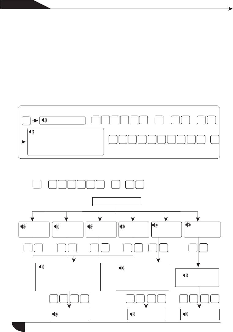
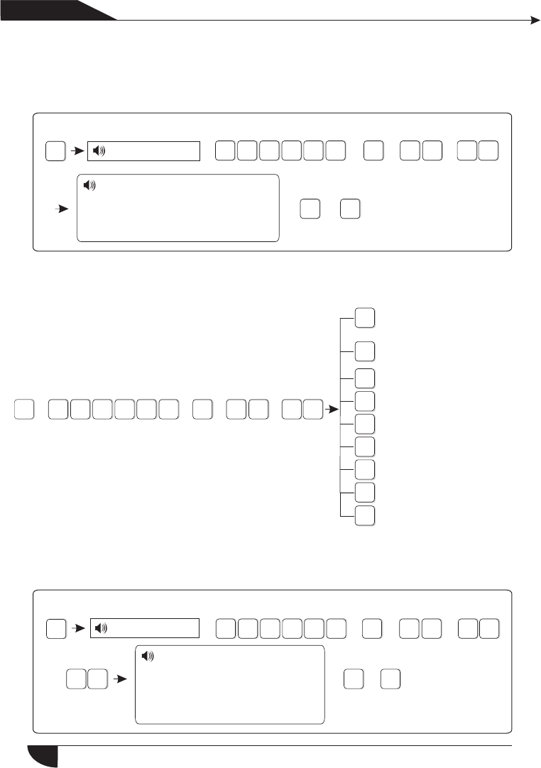
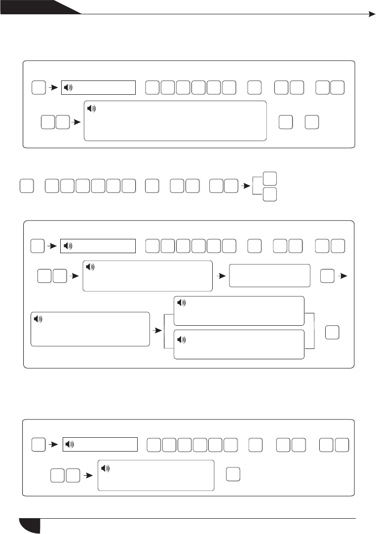
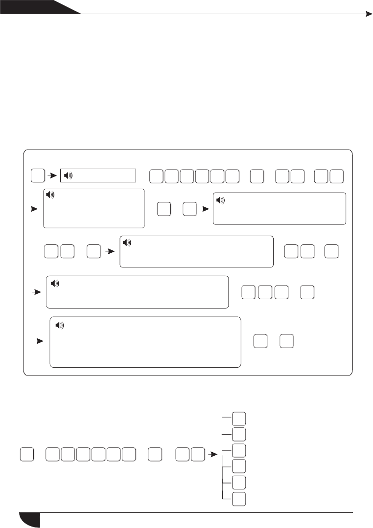
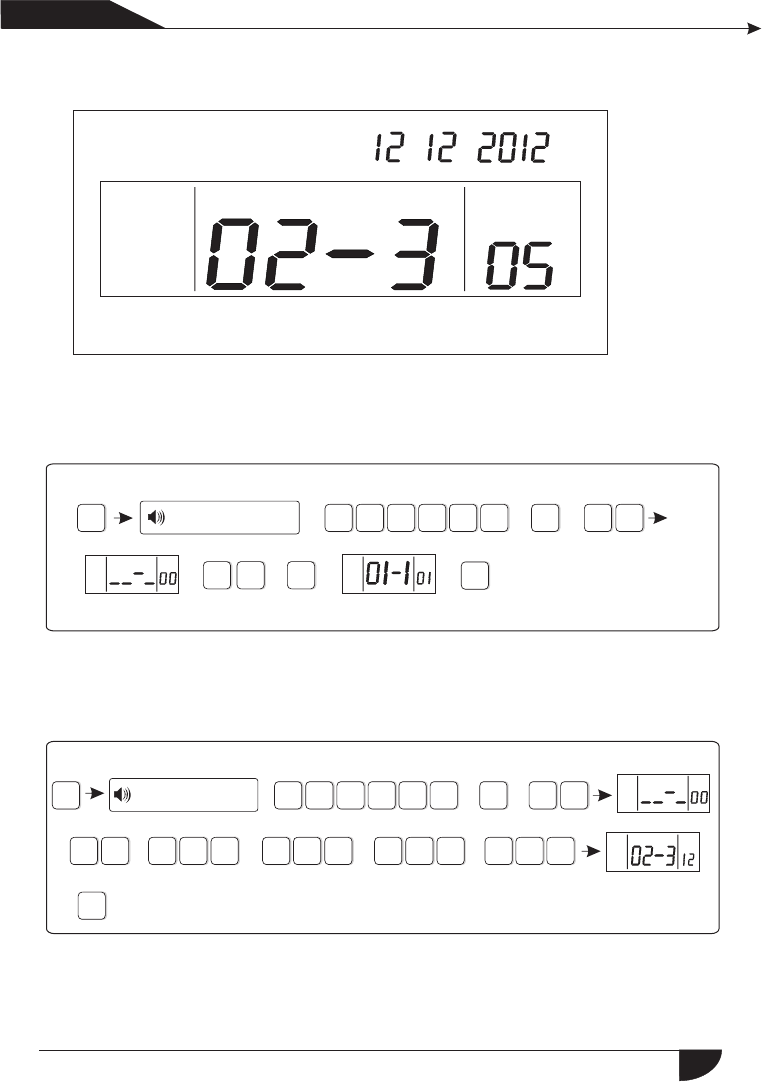
5.1 Set system clock
For example: set system clock as : 22:59:36 22/12/2012
*
Press[*] for 3 seconds
Please enter system
clock, pressconfirm
key tosave,press
back key toexit.
According to flash of Y.M.D.H.Min.Sec on screen, enter 12.12.22.22.59.36
by turn, also can press [UP] [DOWN] key to move cursor.
2 1 2 2 2 2 2
593 6 #
Y M D H
Min Sec on screen
Enter passord +
+
+ +
+ + +
+ + +
For example: Set No.16 user pasword as 5678
*
Press[*] for 3 seconds
#2#
16
+ + +
+
+Enter password, press
confirm key to save,
press back key to exit.
+
+7
6
58
5.2 Set user password
#
Chapter IV Voice alarm receiving
and GSM control
产品 手册
User manual
1
Enter passord 1234
Please enter the serial number
of your modified password,
confirm key to confirm,press
back key to exit.
Note: Can set 16 user passwords, corresponding password No. from 01 to 16,
Only No.1 password can enter user setting.
#
5.3 Set voice phone (refer to page 15)
1 2 34 1 ##
Press[*] for 3 seconds
13
*
8
3
2
1
0
1
2
4
3
5
6
7
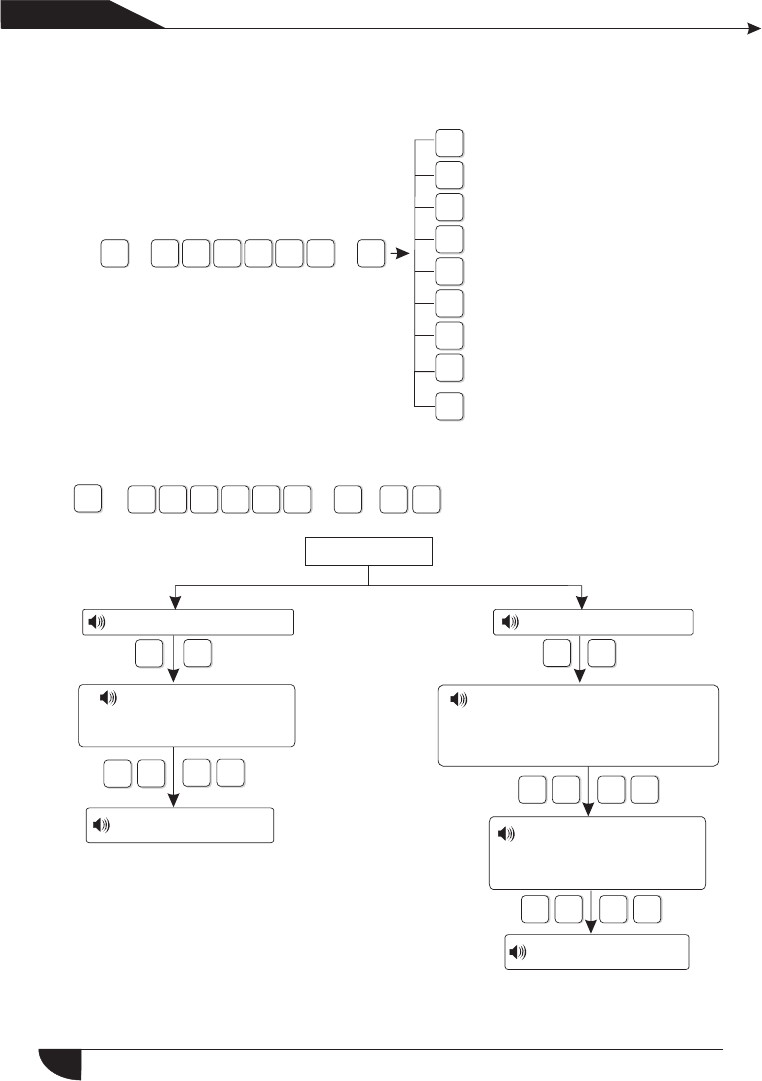
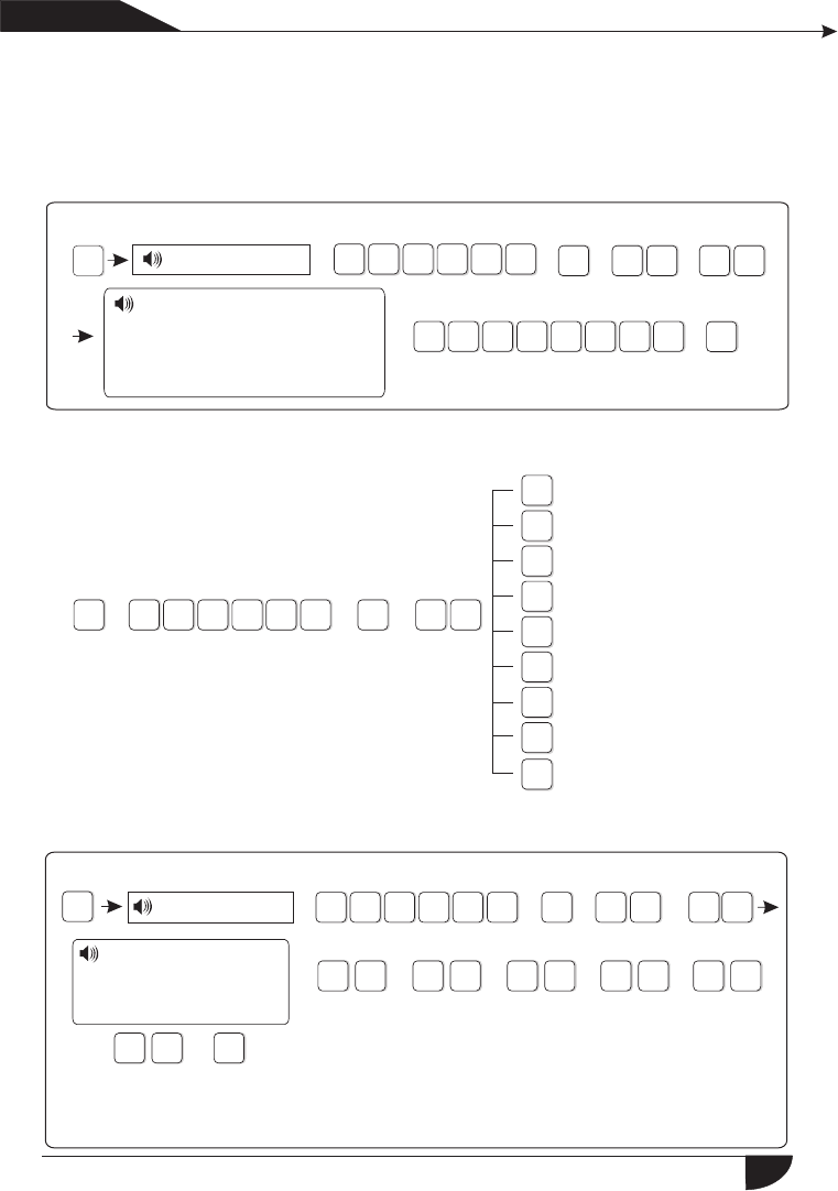
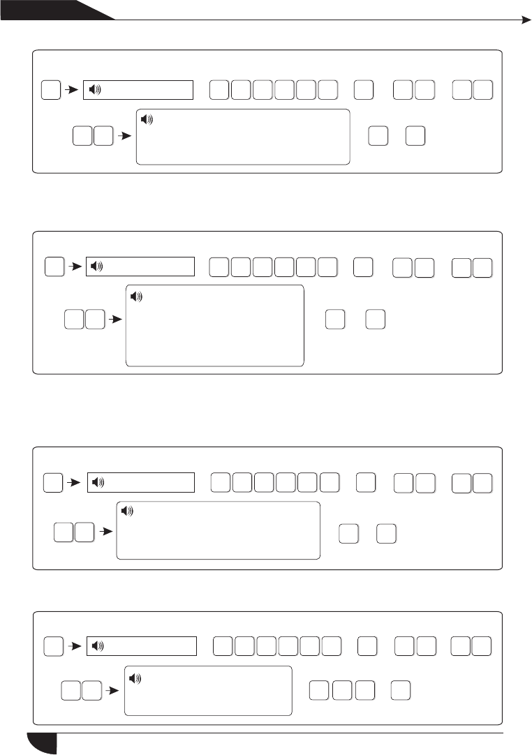
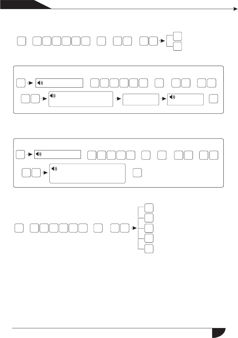
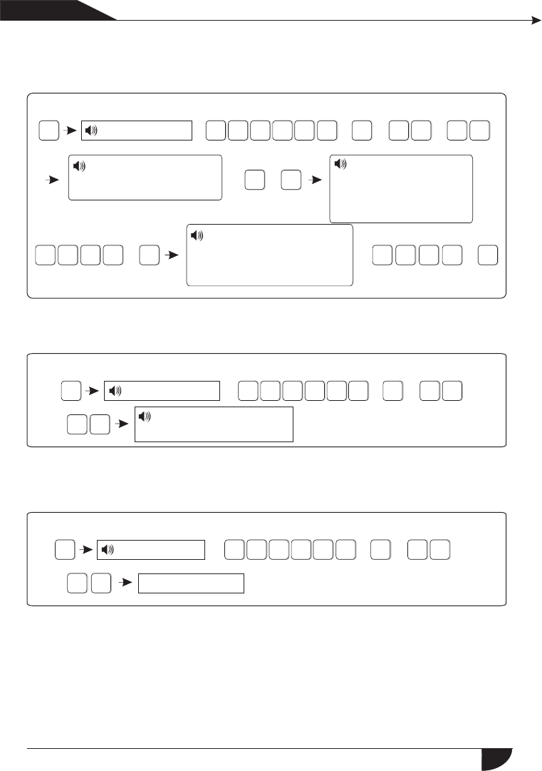
6.1 Set password
Set password
2
[2]Set user password
X X X
1
[1]Set Admin password
XXX
##
##
#
5
4
9
X X X #
+ +
Chapter VI System Setting
*3
2
1
0#
5
4
+ + + 1#
Press[*] for 3 seconds
产品 手册
User manual
Set password
Set CMS number
Set voice phone
Set system options
Set wireless devices
Set zone
System maintenance
Set GSM
Set advanced options
Press[*] for 3 seconds
Then operate according to the
voice prompt as below.
Enter password,
press confirm key to save,
press back key to exit.
The setting is saved
Please enter the serial number
of your modified password, confirm
key to confirm, press back key to
exit press confirm key to save,
Enter password,press
confrim key to save,
Press back key to exit
The setting is saved
14
Note: 1. password setting include “user password” and “ administrator password”,
user password mainly use to disarm the system, it is a private key for remote
controlling, “administrator password” is the sole password to set the system.
Note: 1. password setting include “user password” and “ administrator password”,
user password mainly use to disarm the system, it is a private key for remote
controlling, “administrator password” is the sole password to set the system.
Note: 1. password setting include “user password” and “ administrator password”,
user password mainly use to disarm the system, it is a private key for remote
controlling, “administrator password” is the sole password to set the system.
Note: 1. password setting include “user password” and “ administrator password”,
user password mainly use to disarm the system, it is a private key for remote
controlling, “administrator password” is the sole password to set the system.
Note: 1. password setting include “user password” and “ administrator password”
user password mainly use to disarm the system, it is a private key for remote
controlling, “administrator password” is the sole password to set the system.
For example: Set admin pasword as 888888
#
1
#1#
8888
#
*3
21
05
4
8 8
+ + + +
+
Press[*] for 3 seconds
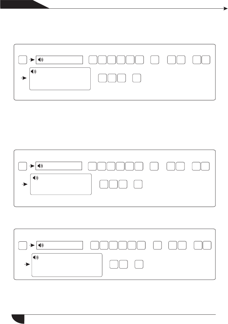
6.2 Set CMS number
Then operate according to the voice
prompt as below:
#
1#
2345
# # #
2#
*3
2
1
0#
5
4
+ + +
Press[*] for 3 seconds
+
XX #
XXX #
X X
X#
X XX #
X
产品 手册
User manual
2.Administrator password is 6 digit, user password is 4 digit, can set 16 user passwords,
corresponding password No. from 01 to 16, but No.2-16 password can’t enter user
setting.
3.If forgot the password, when the alarm is powered on, for the first minute,the
administrator password is 000000.
Enter password
Enter password,press
confirm key to save, press
back key to exit
Note: 1.Above base on the correct operation, if incorrect operation occurs, please
press back key to back previous menu to reset.
2.The factory default of admin password is 9876, user password is 1234, if you
have modified the password, please refer to the new password.
Set CMS
[1] Set CMS
phone number
[2] Set CMS
phone no.2
[3] Set
User Number
[4] Set CMS
dialing times
[5] Set CMS
communication
test interval time
Please enter phone
number, press * key to
delete, Long press 1,
dialing pause 1
second,press confirm
key to save, press
back key to exit.
Please enter
account No. press
confirm key to
save, press back
key to exit
Please enter
dialing times,
press confirm key
to save, press
back key to exit
Please enter
communication
inspection interval
time, 0 for disable,
press confirm key
to save, press back
key to exit
The setting
is saved
The setting
is saved
The setting
is saved
The setting
is saved
15
Press[*] for 3 seconds
Enter password #
91 8 08080#
2#
3
2
1
05
4 1 #
*+ + +
+
+
80+
3#
*3
2
1
0#
5
4
+ + +
#
1#
23#4#5#6#
XX #
X XX #
X XX #
X
产品 手册
User manual
Note: 1.The user code is the identification code in CMS setting, CMS 1 and CMS
2 use the same user code; dialing times can be set 1-15 , communication
inspection interval time can be set 0-999 hours, the common setting is
24 hours.
2.When set phone number, long press 1, display the letter P, means pause
1 second when dialing, when the telephone line which connect to the
alarm panel is sub-line, need a pause dialing.
3.For GSM, just recognize the number behind P, can make sure telephone
and GSM dial the same number.
For example: the sub-line connect to alarm panel, CMS number is 80808080,
in this way, set CMS number like this 9P80808080, 9 is out code.
Please enter phone number,
press * key to delete, Long
press 1, dialing pause 1
second, press confirm key to
save, press back key to exit. Press[1] key for 3 seconds.
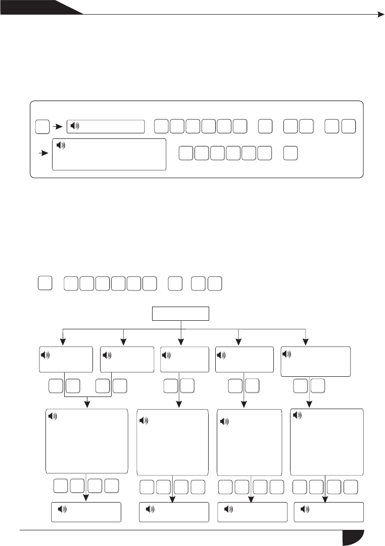
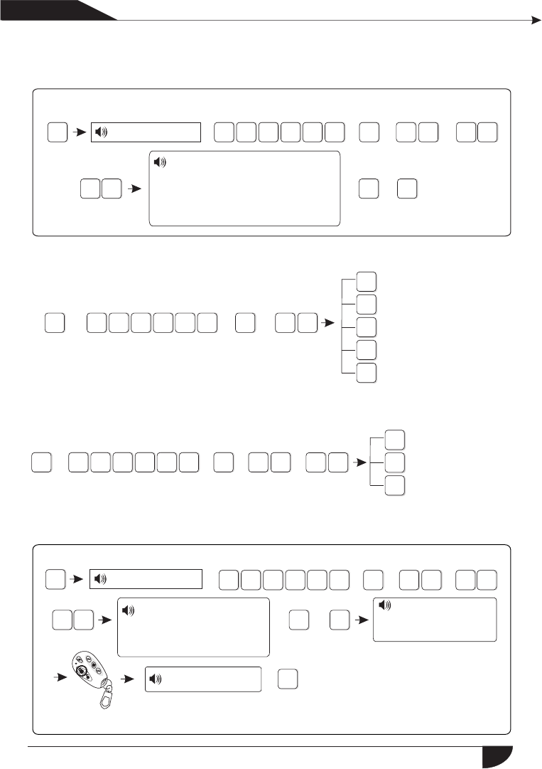
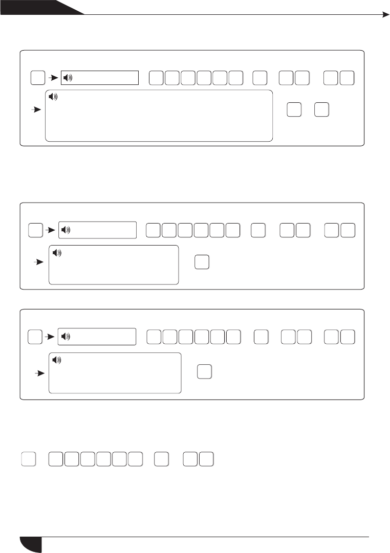
6.3 Set voice phone
Press[*] for 3 seconds
Then operate according to
the voice prompt as below:
Set voice phone
[1] Set
voice phone 1
[2] Set
voice phone 2
[3] Set
voice phone 3
[4] Set
voice phone 4
[5] Set voice phone dialing times
[6] Set voice
phone password
inspection
[5] Set
voice phone
dialing times
The setting
is saved
The setting
is saved
The setting
is saved
1.Enable
2.Disable
Please enter phone
number, press * key to delete,
Long press 1, dialing pause 1
second, press confirm key to
save, press back key to exit.
Please enter dialing
times, press confirm
key to save, press back
key to exit.
16
For example: Set voice phone No.3 is 12345678
*
Press[*] for 3 seconds
#3#
Enter password + + +
3210 54 3#
+
+4
32
16
578#
+
*
8
1
2
4
3
5
6
7
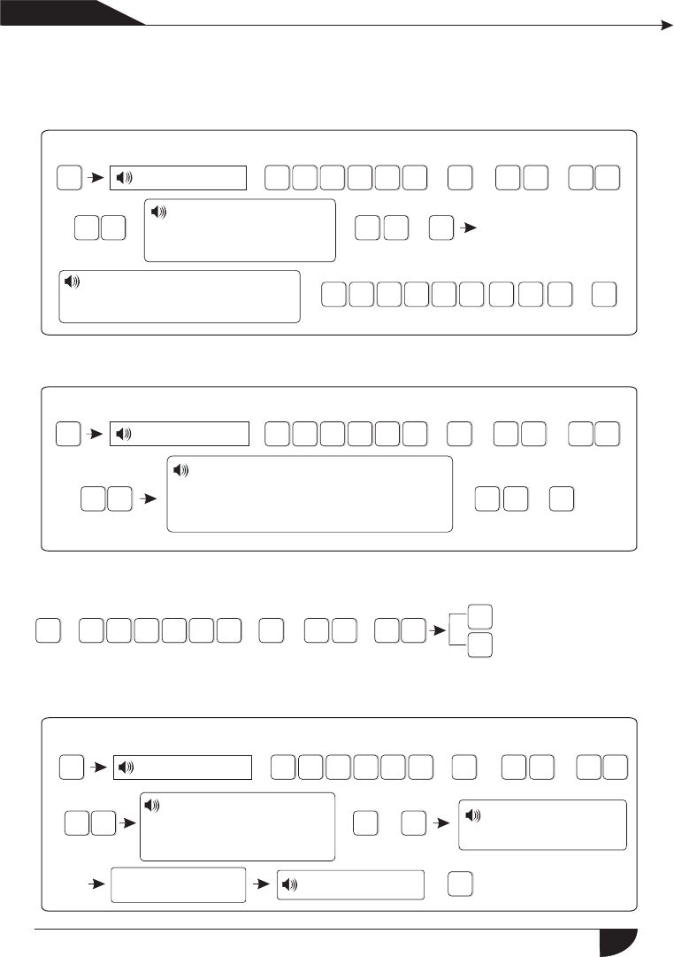
6.4 Set system options
Press[*] for 3 seconds
4#
9
3
2
1
0#
5
4
+ + +
6.4.1 Set system clock
*#4#1#
1212 2 2 2 2 59
3
2
1
05
4
36#
+ + +
+ + +
+ +
+
+
+
产品手册
User manual
Note:1.dialing times can set 1-15
2.When panel call user’s phone, if you enable password check, it will
prompt enter user password when pick up the call.
Please enter phone number,
press * key to delete, Long
press 1, dialing pause 1 se
cond, press confirm key to
save, press back key to exit.
Set system clock
Set entry delay
Set exit delay
Set siren time
Set ring times
Set detector loss inspection
Set arm/disarm tone
Set arm/disarm report
Set others
According to flash of Y.M.D.H.Min.Sec on screen, enter 12.12.22.22.59.36
by turn, also can press [UP] [DOWN] key to move cursor.
For example: Set system time to 22:59:36 22/12/2012
Press[*] for 3 seconds
Enter password
Please enter system
clock, press confirm
key to save, press
back key to exit. Y M D H Min
Sec on screen
17
*#4#2#
0
3
21
05
4
20+#
Enter 3 digit number from 0-255, add 0 if less than 3 digit.
Enter password + ++ +
*Enter password #4#3#
0
3
2
1
05
4
20+#
Enter 3 digit number from 0-255, add 0 if less than 3 digit.
+ ++ +
6.4.3 Set exit delay
After user armed the system, it is convenient for user to exit the area after
arm successfully.( the default setting is 10seconds)
For example: Set exit delay time is 20s
Note: Entry delay is just effective for delay zone. Other zone types can’t
enter delay.
+
#4#4#
3
2
1
05
4
10+#
+ ++
+
+
*
+
产品 手册
User manual
6.4.2 Set entry delay
When trigger alarm, the panel will give delay alarm time(default setting is 10s)
For example: Set entry delay to 20seconds
Press[*] for 3 seconds
Please enter entry
delay time, press
confirm key to save,
press back key to exit
Press[*] for 3 seconds
Please enter exit
delay time, press
confirm key to save,
press back key to exit
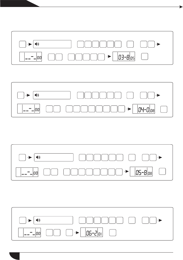
6.4.4 Set siren time :The siren ring time after alarm is triggered( the default
setting is 5 minutes)
For example: Set siren time is 10 minutes
Please enter 0 to 30
minutes siren time, press
confirm key to save, press
back key to exit
Press[*] for 3 seconds
Enter password
6.4.5 Set ring times
User remote control alarm panel, dail the preset phone number, the panel will
off-hook after phone ring times( the default setting is 7 times)
For example: Set ring times is 5
18
#4#5#
3
21
05
4
05+#
+ ++
+
+
*
Note: The max. Ring times as per the local communication, if set 0, not
off-hook.
#4#6#
3
21
05
4
08+#
*
+
+ + + +
#4#7#
3
2
1
05
4
1+#
*
+
+ + ++
产品 手册
User manual
Enter password.... Please enter ring
times, if set as 0, the phone will not
off hook, press confirm key to save,
press back key to exit
Press[*] for 3 seconds
Enter password
Enter 2 digit number from 0-15, add 0 if lower than 10.
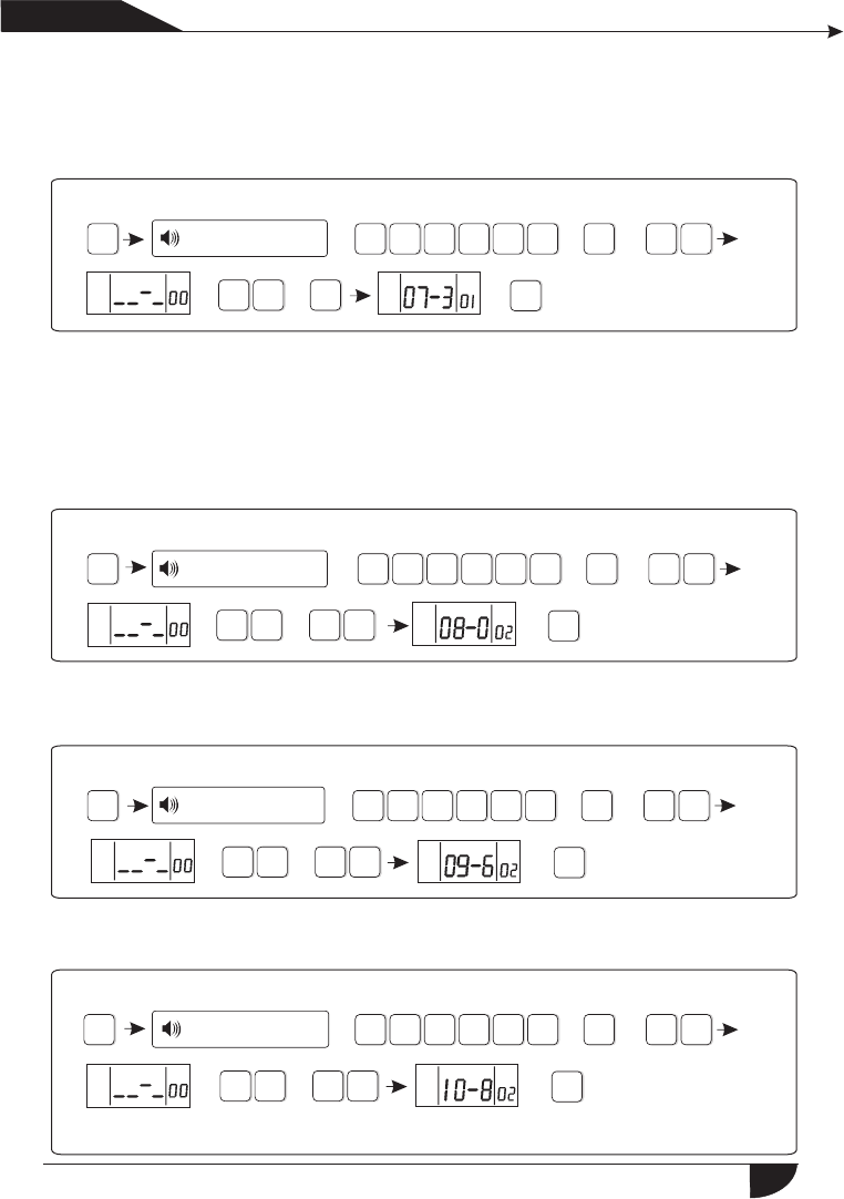
6.4.6 Set detector loss inspection
The alarm panel will inspect the detectors’ status or alarm info in this time
interval, if not receive, it is determined that the detector is loss, the general
setting is not less than 6 hours( the default setting is 0, disable this function)
For example: Set detector loss inspection time is 8 hours.
Please enter 0 to 99 hours detector
loss inspection time, 0 for disable,
press confirm key to save, press
back key to exit
Press[*] for 3 seconds
Enter password
6.4.7 Set arm/disarm tone
When user arm/disarm the system through remote control, if siren will sound
or not for prompting.( the default setting is disabled)
For example: Set siren with short sound when arm/disarm through remote control.
Please choose arm/
tone: 1. siren short sound
2. no voice, press confirm
key to save, press back key
to exit
disarm
Press[*] for 3 seconds
Enter password
19
#4#8#
1#
3
1
05
42
*+ + +
+ +
+
*#4#9#
31
05
4
2
8
1
2
4
3
5
6
7
9
+ + ++
#4#9#
1
3
1
05
4
2
1#
+ +
+
*+
+
+
+#
产品 手册
User manual
Please choose arm/disarm
report: 1. enable, 2. disable,
press confirm key to save,
press back key to exit
Press[*] for 3 seconds
Enter password
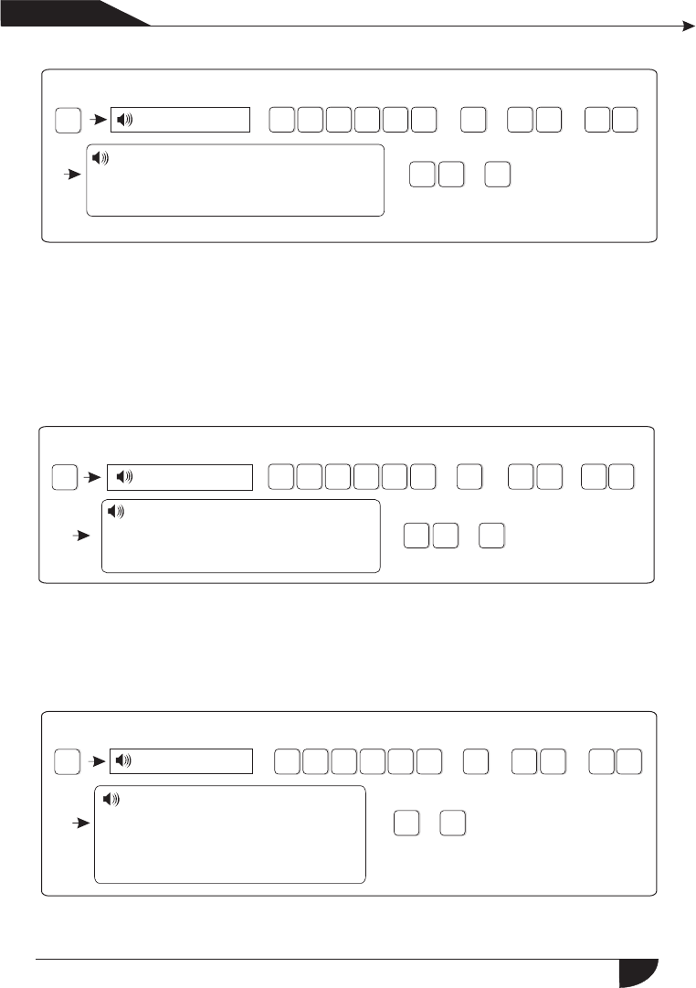
Set AC off remind
6.4.9 Set others
6.4.9.1 Set emergency alarm siren type( the default setting is mute)
For example: set emergency alarm siren type is pedal point.
Please choose zone siren
type: 1.pedal point 2.pulse
tone 3. mute, press
confirm key to save, press
back key to exit
Press[*] for 3 seconds
Enter password
Set emergency alarm
siren type
Set AC off inspection time
Enable magnetic contact
inspection
Check wireless detector
tamper
Set force arm
Set telephone line
disconnect remind
Set zone alarm times
Set listen-in time
6.4.8 Set arm/disarm report
Set if arm/disarm report to CMS or not( the default setting is disabled)
For example: Set arm/disarm report to CMS
20

#4#9#
01#
3
2
1
05
4
2#5
*+ + +
+ + +
+
#4#9#
1#
3
2
1
05
4
3#
*+ + +
+ + +
+
#4#9#
2#
3
2
1
05
4
4#
*+ + + +
+ ++
产品 手册
User manual
6.4.9.2 Ac off inspection time setting. When the AC power is off, delay to report
to CMS(factory default delay time is 30 min)
Example:set AC off inspection time as 15 min
Press[*] for 3 seconds
Enter password
Plsease enter 0 to
AC off duration time.press
confirm key to save, press
back key to exit.
255 minutes
6.4.9.3 Magnetic contact inspection: Set if the alarm panel show zone trouble
on LCD screen or not when sperate the magnetic strip from transmitter.
(Factory default disable the inspection)
Example: enbale the magnetic contact inspection
Press[*] for 3 seconds
Enter password
6.4.9.4 Check wireless detector tamper: if the enable the checking when
trigger the detector’s tamper , will trigger alarm. If disable the
checking, it will not trigger alarm.(factory default enable the checking)
Example: disable the checking of wireless detector tamper.
Press[*] for 3 seconds
Enter password
6.4.9.5 Set force arm: if enabel set force arm, when there is zone trouble, the
system can be armed and report the trouble zone’s bypass message
to CMS. If disable the force arm, the system can not be armed(factory
default is disable forem arm)
Example: enabel force arm
Please choose: 1. Enable
contact inspection 2. Disable
Press confirm key to save,
Pressback key to exit.
magnetic
Please choose : 1. Enable
detector tamper inspection, 2. Disable
wireless
Press confirm key to save,
Pressback key to exit.
21
#4#9#
1#
3
2
1
05
4
5#
*+ + + +
+ + +
#4#9#
3#
3
2
1
05
4
6#
#4#9#
2#
3
2
1
05
4
7#
*
+ +
+ + +
+
+
*+ + +
+ +
+
#4#9#
0#
3
2
1
05
4
8#20
*+ + +
+ +
+
+
产品 手册
User manual
Press[*] for 3 seconds
Enter password
Press[*] for 3 seconds
Enter password
Press[*] for 3 seconds
Enter password
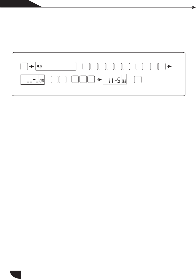
6.4.9.6 Set telehpone line disconnect remind(factory default delayed
siren sound remind)
Example : disable telephone line disconnet remind
6.4.9.7 set zone alrm times: if set the alarm alarm times as 1, when
zone start alarm but the zone is trigger one time again, the panel
will not make alarm.
Example: set zone alarm times as 1 time
6.4.9.8 set listen-in time(factory default 10 sec)
Example: set listen-in time as 20sec
Press[*] for 3 seconds
Enter password
Please choose: 1. Auto force
2. Forbid force arm via remote
control.
arm
Press confirm key to save,
pressback key to exit.
Please choose telephone
line disconnect remind:
1. Siren delay remind,
2. Buzzer remind, 3 disable
Press confirm key to save,
Pressback key to exit.
Please choose zone alarm times:
1. no limited 2. 1 time
Press confirm key to save,
Pressback key to exit.
Please enter 10 to 255
seconds listen-in time
Press confirm key to save,
Pressback key to exit.
22
*#5#
3
2
1
05
4
1
2
4
3
5
+ ++
#4#9#
#
3
21
05
4
9#3
*+ + + +
+ + +
*#5#
3
2
1
05
4
1
2
3
1#
+ + +
+
#5#1#
#
3
2
1
05
4
1#3
#
*+ + + +
+ + +
+
产品手册
User manual
6.4.9.9 Set AC off remind(factory default remind by SMS)
Example:disable AC off remind
Press[*] for 3 seconds
Enter password
6.5 manage wireless device
Press[*] for 3 seconds
Set remote control
Set detectors
Set appliance switch
Enroll wireless siren
Set door bell
Enroll remote control
Enter remote control code
Delete remote control
6.5.1 set remote control
Press[*] for 3 seconds
6.5.1.1 enroll remote control
Example: enroll remote to the #3 remote in alarm panel
Press[*] for 3 seconds
Enter password
Please choose AC off remind:
1. SMS remind 2. Voice phone
remind 3. Disable
Press confirm key to save,
Pressback key to exit.
Please enter the serial
number of remote control
Press confirm key to save,
Pressback key to exit.
Please trigger the
remote control
Pressback key to exit.
Enroll successful
Trigger arming key on the remote control
23

#5#1#
#
3
2
1
05
4
2#8
2
11 11 13 41 #
*+ + +
+ + +
+
+
#5#1#
#
3
21
05
4
3#5
*
+ +
+ + + +
+
*#5#
3
2
1
05
4
1
2
3
2#
+ ++ +
#5#2#
3
2
1
05
4
1#09
#
*+ + +
+
+
+
+#
+
产品 手册
User manual
6.5.1.2enter remote control code
Example: manaul enter the address code of remote 112113114 to the #8
remote in alarm pa
Press[*] for 3 seconds
Enter password
6.5.1.3 delte remote control
Example: delete the # 5 remote
Press[*] for 3 seconds
Enter password
6.5.2 set detector
Press[*] for 3 seconds Detector coding
Enter detector code
Delete detector
6.5.2.1 detector coding
Example: auto code detector to # 9 detector in alarm panel
Press[*] for 3 seconds
Enter password
Please enter the number
of remote control.
serial
Press confirm key to save,
Pressback key to exit.
Press confirm key to save,
Pressback key to exit.
Please enter remote
control Number +
Please enter the serial number of remote
control to delete, enter 0 to delete all.
Press confirm key to save,
Pressback key to exit.
Press confirm key to save,
Pressback key to exit.
Please enter
detector Number Please trigger the
detector
Pressback key to exit.
Enroll successful
trigger the detector
24
#5#2#
3
2
1
05
4
2#07
00
11
022 3 3 #
#5#2#
3
2
1
05
4
3#03#
*#5#3#
3
21
05
41
2
*+ + +
++
+
+
*
+
+ + +
+ + +
+
#
+
+
+ + ++
#5#3#
3
2
1
05
4
1#1#
#
*+ + +
+ + +
+
+
产品 手册
User manual
Press[*] for 3 seconds
Enter password
6.5.2.2 enter detector code
Example: manual enter the address code of detector 011022033 to
the # 7 detector in alarm panel
6.5.2.3 delete detector
Example: delete the # 3 detector
Press[*] for 3 seconds
Enter password
6.5.3 set appliance switch
Press[*] for 3 seconds
Enroll appliance switch
Delete appliance switch
6.5.3.1 enroll appliance switch
Example: auto the appliance to the # 1swith in alarm panel
Press[*] for 3 seconds
Enter password
P l e a s e e n t e r
detector Number.
Press confirm key to save,
Pressback key to exit.
Please enter detector code
Press confirm key to save,
Pressback key to exit.
Please enter the serial number of
detector to delete, enter 00 to delete all.
Press confirm key to save,
Pressback key to exit.
Please enter the serial
number of appliance switch
Press confirm key to save,
Pressback key to exit.
Pressback key to exit.
Please trigger
appliance switch
Trigger appliance
switch Enroll successful
25
#5#3#
3
2
1
05
4
2#4#
1
2
*#5#4#
3
2
1
05
4
#5#4#
3
2
1
05
4
1#
#
#
*+ + + +
+ +
*+ + +
+ + +
+
+ + ++
+
#5#4#
3
2
1
05
4
2##
按 3秒以 上[*]
*++ + +
+
+
产品 手册
User manual
6.5.3.2 Delete appliance switch
Press[*] for 3 seconds
Enter password
Enroll wireless siren
Delete wireless siren
6.5.4 Enroll wireless siren
6.5.4.1 Enroll wireless siren
Press[*] for 3 seconds
Enter password
NOTE: when dual-way wireless siren make tamper alarming, the LCD screen
of alarm panel will display zone 41 alarming.
6.5.4.2 Delete wireless siren
Note: It is dual-way wireless siren deleted.
Please enter the serial number of appliance
switch to delete, enter 0 to delete all
Press confirm key to save,
Pressback key to exit.
Please make wireless siren
under coding status, then press
confirm key to start coding.
Make wireless siren
under coding status
Start siren coding, please
operate as voice prompting
Pressback key to exit.
This is one way wireless siren
Press confirm key to save,
Pressback key to exit.
This is 2-way wireless siren
Press confirm key to save,
Pressback key to exit.
Delete wireless siren
Press confirm key to save,
Pressback key to exit.
Enter password
26
Example: delete the # 4 appliance switch
#5#5#
3
2
1
05
4
1# #
1
2
*#5#5#
3
2
1
05
4
6.5.5.1Enroll doorbell
Note: can only learn a wireless doorbell, the trigger will be issued after the chink
#5#5#
3
2
1
05
4
2# #
*+ + +
+ +
*+ + ++
+
+ + ++
+
6.5.5.2 Delete doorbell
+
+
6.6 Sector Settings
*#6#
3
2
1
05
4
1
2
3
4
5
++ +
产品 手册
User manual
6.6.5 Set door bell
Set zone attribution
Set zone siren type
Set wired zone loop type
Set wired zone response speed
Set related zone
Press[*] for 3 seconds
6.6.1 set zone attribution
The type of zone attributuion is as below:
0)disable zone 1> delay zone 2> perimeter zone
3>inerior zone 4>emergency zone 5> 24 hours zone
6>fire zone 7> key zone
Enroll doorbell
Delete doorbell
Press[*] for 3 seconds
Enter password
Press[*] for 3 seconds
Enter password
Please trigger doorbell
Pressback key to exit.
Please trigger
doorbell Enroll
successful
Press confirm key to save,
Pressback key to exit.
Delete doorbell
27
1.Zone attribution is the alarm type of the zone display on the alarm panel’
s LCD screen when the zone is triggered. When set the zone attribution as
0 is to disable the zone. The alarm panel will not make alarm when trigger
this zone.
#6#1#
3
2
1
05
4
3#
9
*+ + +
+ +
+
7#
+ +
Example: set zone 39 as keyzone type
2.interior zone only trigger alarm when the zone is triggered under system at
armed status.
3.delay and perimeter zone trigger alarm when the zone is triggered under
system at armed or home arm status.
4.emergency zone, 24 hours zone, fire zone will trigger alarm when system
at any status
5.wirelss zone can not set key zone type. When wired zone is set as keyzone,
trigger the zone, system turn to disarm status. The zone restore, system turn
to armed status. This is for access contron system.
#6#2#
3
21
05
4
2#
3
*++ + +
+ +
产品 手册
User manual
Press[*] for 3 seconds
Enter password
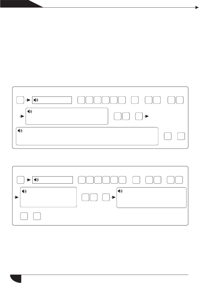
6.6.2 set zone siren type(factory default is pefal point)
Example set zone 23’s siren type as pulse tone
Enter password
Press[*] for 3 seconds
Please enter the zone No. to modify.
Press confirm key to save,
Pressback key to exit.
Please choose zone type:
0. Disable the zone 1. Delay zone 2. Perimeter zone 3. Interior zone
4. Emergency zone 5. 24 hours zone 6. Fire zone 7. Key zone
Please enter the zone
number to modify.
Press confirm key to save,
Pressback key to exit.
Please choose zone siren type:
1.pedal point 2.pulse tone 3. Mute
Press confirm key to save,
Pressback key to exit.
#
2
+ +
6.6.3 set wired zone loop type(factory default EOL )
The options is as below:
28
1>EOL loop type: when the resistor value is 10k on the zone is normal, when
the zone is open loop or shortcut trigger alarm
2>N/C loop type: zone shortcut is normal, open loop trigger alarm
3>N/O loop type: zone open loop is normal, shortcut loop trigger alarm
#6#3#
3
21
05
4
#
3#
5
3
#6#4#
3
2
1
05
4
#
4#
0
2
*+ + +
+ +
+ +
+
*+ + +
+ +
+ +
+
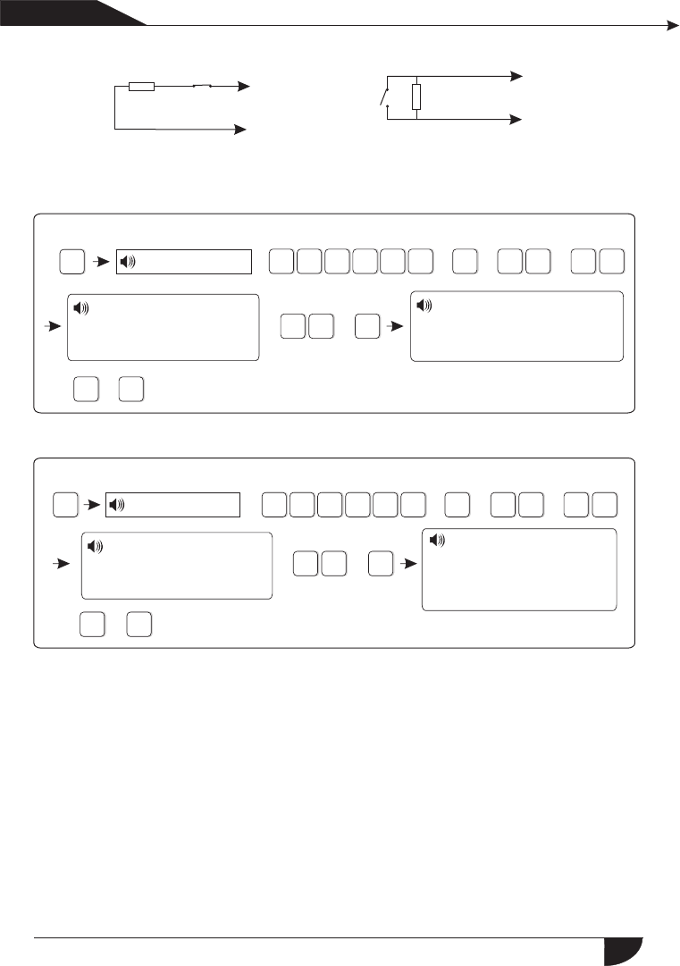
NC
10KΩ
NO 10KΩ
6.6.5 set related zone: zone 1+zone 2+related time+mode
The options as belows
0>disable related zone mode
1>EXIT-ENTRANCE dual trigger mode: trigger zone 1 or 2 seperately will
not trigger alarming. Trigger zone 1 first, then during the period of related
time trigger zone 2, then both zone 1 and 2 trigger alarm.Trigger zone 2
first, then trigger zone 1 will not trigger alarm.
Z
C
Z
C
产品手册
User manual
EOL loop
N/C wiring diagram
EOL loop
N/O wiring diagram
6.6.4 set wired zone response speed(factory default is 500 millisecond)
Press[*] for 3 seconds
Enter password
Example: set zone 35 as N/O loop type
Press[*] for 3 seconds
Enter password
Note: Normall the detector’s response speed is 500 millisecond, high speed
response detector like vibration detector is 10 millisecond
Please enter the zone
number to modify
Press confirm key to save,
Pressback key to exit.
Please choose loop type:
1.EOL 2.N/C, 3.N/O
Press confirm key to save,
Pressback key to exit.
Please enter the zone
numbEr to modify
Press confirm key to save,
Pressback key to exit.
Please choose loop
response speed: 1. 500ms,
2. 10ms
Press confirm key to save,
Pressback key to exit.
29
#6#5#
3
2
1
05
4
#
4#
5#
0
NOTE: max set 4 group relate zone
6.7 system maintance
*#7#
3
2
1
05
4
1
2
3
4
5
6
*+ + +
+ +
+ +
+
0+9
#
2
+ +
0
1
#
+ +
3
+ ++
+
产品 手册
User manual
2>EXIT-ENTRANCE single trigger model: trigger zone 1, zone 1 make alarm.
Trigger zone 2 first, then during the period of related time trigger zone 1,
do not make alarm. Trigger zone 2, then do not trigger zone 1 during related
time, then zone 2 make alarm.
3> Dual trigger alarm mode: trigger zone 1 or zone 2 only do not make alarm.
During related time trigger zone 1 or zone 2, then zone 1 or zone 2 make alarm.
Example: set zone 5 and zone 9 as greep #4 dual trigger mode related zone,
related time is 120sec.
Press[*] for 3 seconds
Enter password
Press[*] for 3 seconds
Set timing arm /disarm
Recording
Play recoreding
Set programmable output port
Delete system log
Restore to factory default
Eneter correlate group
# , press confirm key to
confirm or press back key
to exit setting.
Enter the firstcorrelate zone #
press confirm key to savesetting,
or press back key to exit setting.
Settingsaved, enter second related
zone #, press confirm key to save
setting or press back key to exit setting
Setting is saved, press set relate time from
2 to 255sec, and press confirm key to save
setting, or press back key to exit setting
Setting is saved, pls choose relate mode. 0
disable relate mode , 1 entrance-exit dual
trigger mode, 2 entrance-exit single trigger
mode, 3 dual trigger mode. Press confirm
key to save setting or press back key to exit.
30
#7#1#
3
2
1
05
4
1#
70
*+ + +
+
+ +
+
30830#
#7#
2#
3
21
05
4
*++
+
+
#
+
3
+
#7#
3#
3
2
1
05
4
*+ +
+
+
+
6.7.1 Set timing operation
Example: Set group No.3 as timing disarm at 8:30, and timing arm at 17:30
[*]
Press for 3 seconds
产品手册
User manual
Enter password
[*]
Press for 3 seconds
Enter password
Please enter timing arm
/disarm group number
Please enter timing
arm time, 00 is invalid
time.Press confirmkey
to save, pressback
key to exit.
Please enter timing disarm
time, 00 is invalid time.
Press confirm key to save,
press back key to exit.
Hint: 4 groups of timing arm/disarm can be set according to the schedule of user.
6.7.2 Recording
Start to record when you
hear “Bi” sound
Hint: 15 seconds for recording time. And it will play recording as soon as the
panel dial to the telephone No.as preset.
6.7.3 Play recording
Press * for 3 seconds.
Enter password
6.7.4. Set programmable output port: the voltage will change from 0V to
14.5V as soon as some events occurs. (Default is follow alarm output)
Trigger events can be set as below
1. Follow alarm output 2. Follow arm output
3. Follow AC power fault output 4. Follow communication fault output
5. Password control output
Play the recording
31
#7#4#
3
2
1
05
4
#
5
*#7#5#
3
21
05
4
#
*#7#6#
3
2
1
05
4
#
*+ + +
+ +
+
+
+
+ ++
+
+
+ + +
产品 手册
User manual
For example: Set as password control output
Press[*] for 3 seconds
Enter password
Please select programmable output port follow event
1.Follow alarm output 2.Follow arm output
3.Follow AC power fault output
4.Follow Communication fault output
5.Password control output
Hint: when setting as password control output, press key 5 for 3 seconds,
then enter the user password, the programme output port will be open
or closed. Voice phone or SMS also can open or close the outport.
Press[*] for 3 seconds
Enter password
6.7.6.Restore to factory default
Press * for 3 seconds
Enter password
Please re-confirm to restore
to factory default.
Press confirm key to save,
press back key to exit.
Please re-confirm to restore
to factory default.
Press confirm key to save,
press back key to exit.
*#8#
3
2
1
05
4+ ++
6.8. Set GSM module
Press[*] for 3 seconds
For example: Set enable GSM module, telephone line priority, Set GSM bill
reminder time is 21st Dec. 2012.
The voice prompt will instruct you
to proceed below operations.
32
6.7.5.Delete system events
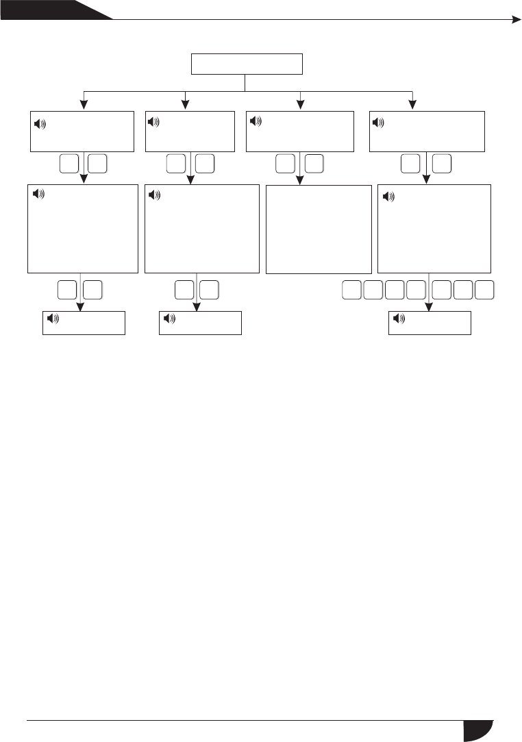
[1]Set GSM
disabled/enabled
[2]Set GSM
in priority
# # ##
1#2#2
12
121#
[3]GSM signal
display
[4]Set GSM bill
reminder time
3
2
1 4
产品 手册
User manual
Set GSM module
Please choose
1> enable GSM
2> disable GSM,
Press confirm key
to save, press
back key to exit.
The maximum
signal intensity
can be displayed
in LCD is 31,
press back key
to exit.
Please choose
1> GSM in priority
2> PSTN in priority,
Press confirm key
to save, press back
key to exit.
Please enter SIM
card expiry time,
Press confirm key
to save, press back
key to exit.
The setting
is saved
The setting
is saved
The setting
is saved
Hint: The alarm control panel will send SMS to cellphone as preset and remind
you to recharge as you set GSM bill reminder time before or after ten days.
33

产品 手册
User manual
6.9 Advanced setting options
Without voice prompt, programme address and the corresponding options
as below table.
59 Sensor recovery 5
60 Sensor loss 5
61 System low battery 5
62 System AC loss 5
63 System AC recovery 5
64 Zone bypass 5
65 Telephone line fault 5
66 Periodic test report 5
67 Wireless zone loop trouble 0
68 Wireless zone loop recovery 0
69 System battery recovery 0
70 Communication trouble 0
71 Bypass cancel 0
72 Alarm cancel 0
73 Disarm 0
74 Armed stay 0
75 Armed 0
76 Panel programming changed 0
77 System alarm failure 5
78 Telephone line recovery 4
79 Communication recovery 4
01 GPRS enable and disable
02 Set sever IP address
03 Set sever port
04 Set user ID
05 Set user password
06 GSM SMS language
07 Delay zone tone source options
08 Handshake tone input signal
intensity
09 DTMF output signal intensity
10 Set LCD standby brightness
11 Alarm event retain time
50 System 00 zone 7
51 Delay zone 7
52 Perimeter zone 7
53 Interior zone 7
54 24 Hour zone 7
55 Emergency zone 7
56 Fire zone 7
57 Tamper zone 7
58 Sensor low battery 5
Programming address 50-79 are correspond to the options for the alarm
content, the right of data are factory default.
Set alarm data as below:
0. Do not send any information
1.Only send SMS.
2.Only telephone line
3.SMS+telephone line
4.Only upload to CMS
5.Upload to CMS+SMS
6.Upload to CMS+telephone line
7.Upload to CMS+SMS+telephone line
34
LCD display direction
YDM
*#9#
0
3
2
1
05
4
#
+1+1+
+ +
+
+
*#9#
3
21
05
4
#
+
+2
0+0
10
35
+ +
1
98
00 0 3
+ + +
+
产品 手册
User manual
Programming
address
Press key up and down to check and modify the different data of the data bit.
Data Data bit
6.9.1 GPRS enable and disable(1. Enable 2. Disable default is 2 )
For example: set enable GPRS
Press[*] for 3 seconds
Enter password
LCD display Programming
address Data LCD display
Hint: Priority to enable the GSM module before enable the GPRS
6.9.2 Set sever IP address
For example: Sever IP address is 103.59.108.3
Press[*] for 3 seconds
Enter password
Less than 3 bits high zero.
35
*#9#
3
21
05
4
#
+
+4
0+0
50
5 5 5
0 0
*#9#
3
2
1
05
4
#
+
+3
0+0
80
8 8
+
+
+
+
+
+
*#9#
3
21
05
4
#
+
+5
0+21 4
35 7
68
+ +
+
*#9#
3
2
1
05
4
#
+
+6
0+2
+ +
+
产品 手册
User manual
6.9.3 Set sever port
For example: Sever port as 80808
Press[*] for 3 seconds
Enter password
6.9.4 Set user ID
For example: User ID as 50505050
Press[*] for 3 seconds
Enter password
User ID must be 8 bits
6.9.5 Set user password
For example: User password as 12345678
Press[*] for 3 seconds
Enter password
User password must be 8 bits
6.9.6 GSM SMS language(1. Chinese 2. English Default is 1 Chinese)
For example: Set GSM SMS language as English
Press * for 3 seconds
Enter password
36
*#9#
3
21
05
4
#
+
+7
0+3
*#9#
3
2
1
05
4
#
+
+8
0+0
7
6.9.9 DTMF output signal intensity(The default is 04)
For example: set the DTMF output signal strength to 06
*#9#
3
21
05
4
#
+
+9
0+6
0
+ +
+
+ +
+
+
++
*#9#
3
21
05
4
#
+
+0
1+8
0
+
+
+
产品 手册
User manual
6.9.7 Delay zone tone source options
1. Dingdong 2. Welcome 3. Recording 4. Didi
For example : Delay zone tone source as recording
Press[*] for 3 seconds
Enter password
Hint: In disarm mode, once delay zone triggered and above 4 voices will be
generated. press key 4 for 3 seconds and input the user password can
be open and close it.When the tone source is recording mode, the voice
phone will not play the recording.
6.9.8 Handshake tone input signal intensity ( default is 60)
For example: set it as 70
Press[*] for 3 seconds
Enter password
Press[*] for 3 seconds
Enter password
6.9.10 Set LCD standby brightness (default is 02)
For example: Set it as 22
Enter password
Press[*] for 3 seconds
Brightness range: 0-10,Less than 2 bits high zero
37
For example: set the alarm information retention time is 255 minutes
*#9#
3
2
1
05
4
#
+
+1
1+5
25+
++
产品 手册
User manual
6.9.11 Alarm event retain time
When telephone line and GSM all fault, the alarm event will be retained in
the preset time. Otherwise it will loss. After telephone line and GSM recovery,
it will upload to the CMS. (default time is 10 mintus).
Retain time :1-255 mintus.Less than 3 bits high zero.
Press[*] for 3 seconds
Enter password
38

39
产品手册
User manual
Chapter VII technical specification
7.1 General data
1.Power supply: 15V/2000mA
2.Built in rechargeable battery:11.1V/1000mah
3.System static current: <50mA(exclude wireless detector)
4.System alarming current: <300mA(exclude wireless high siren
current)
5.System maximum output current: ≤100mA(supply wireless
detector)
6.Frequency:433MHz/868MHz
7.Signal transmit distance: 100 to 150 meters (open area)
8.The method of alarming dial: DTMF GSM or GPRS
9.Communication protocol with CMS: Ademco Contact ID
10.DTMF dial frequency variation:,1.5%
11.Recording time:15s
7.2 Physical performance
Operation temperature range: 0℃-45℃(32F-120F
Storage temperature range: -20℃-60℃(-4F-140F)
Relative humidity: 85% at 30℃(86F)
Color: as box indicated.

40
产品 手册
User manual
Chapter VIII maintenance
8.1 Regular test
Design of components of the system is to reduce maintenance cost,
but still it is suggested that periodical check may be carried out.
8.2 The cleanliness of control main machine
Main control panel may be stained by fingers or covered by dust after
using for a while. Use soft cotton cloth or sponge to clean it, don't use
any lubricant, liquid such as kerosene, acetone and strong gel which
will damage appearance and the transparency of top window.
Attention: don't use any lubricant, liquid such as kerosene, acetone
and strong gel which will damage appearance and the top transparency
of window.
Chapter VX limitation of the products
Although the products is a high standard products, there is also some
limitation of them such as false alarm or no alarm. The reasons may be
below:
Lack of maintenance, the system needs maintenance and test
regularly test the sensitive of the detector may decrease and the siren
may not whistle.Lack of power supply if no power input and the back up
power is not enough, the panel can not work normally.Telephone line
false, if the telephone line is cut, the panel could not send alarm signals.
Limitation of smoke detectors, if the smoke is far from the smoke
detector, the detector could not alarm.If the intrude break in through
some door or window not monitored. Or someone know how to make
the system not work.
FCC WARNING
Changes or modifications not expressly approved by the party responsible for compliance
could void the user's authority to operate the equipment.
This equipment has been tested and found to comply with the limits for a Class B digital
device, pursuant to Part 15 of the FCC Rules. These limits are designed to provide
reasonable protection against harmful interference in a residential installation. This
equipment generates uses and can radiate radio frequency energy and, if not installed and
used in accordance with the instructions, may cause harmful interference to radio
communications. However, there is no guarantee that interference will not occur in a
particular installation. If this equipment does cause harmful interference to radio or
television reception, which can be determined by turning the equipment off and on, the
user is encouraged to try to correct the interference by one or more of the following
measures:
-- Reorient or relocate the receiving antenna.
-- Increase the separation between the equipment and receiver.
-- Connect the equipment into an outlet on a circuit different from that to which the
receiver is connected.
-- Consult the dealer or an experienced radio/TV technician for help FCC Radiation
Exposure Statement The antennas used for this transmitter must be installed to provide
a separation distance of at least 20 cm from all persons and must not be collocated or
operating in conjunction with any other antenna or transmitter.