METRIC SYSTEMS 50739 BROADBAND VHF/UHF NETWORKING RADIO SYSTEM User Manual
METRIC SYSTEMS CORPORATION BROADBAND VHF/UHF NETWORKING RADIO SYSTEM Users Manual
UserManual.wiki
>
METRIC SYSTEMS
>
50739 User Manual
Users Manual
Navigation menu
Upload a User Manual
Namespaces
Wiki Guide
HTML
PDF
Info
Views
User Manual
Discussion / Help
Navigation

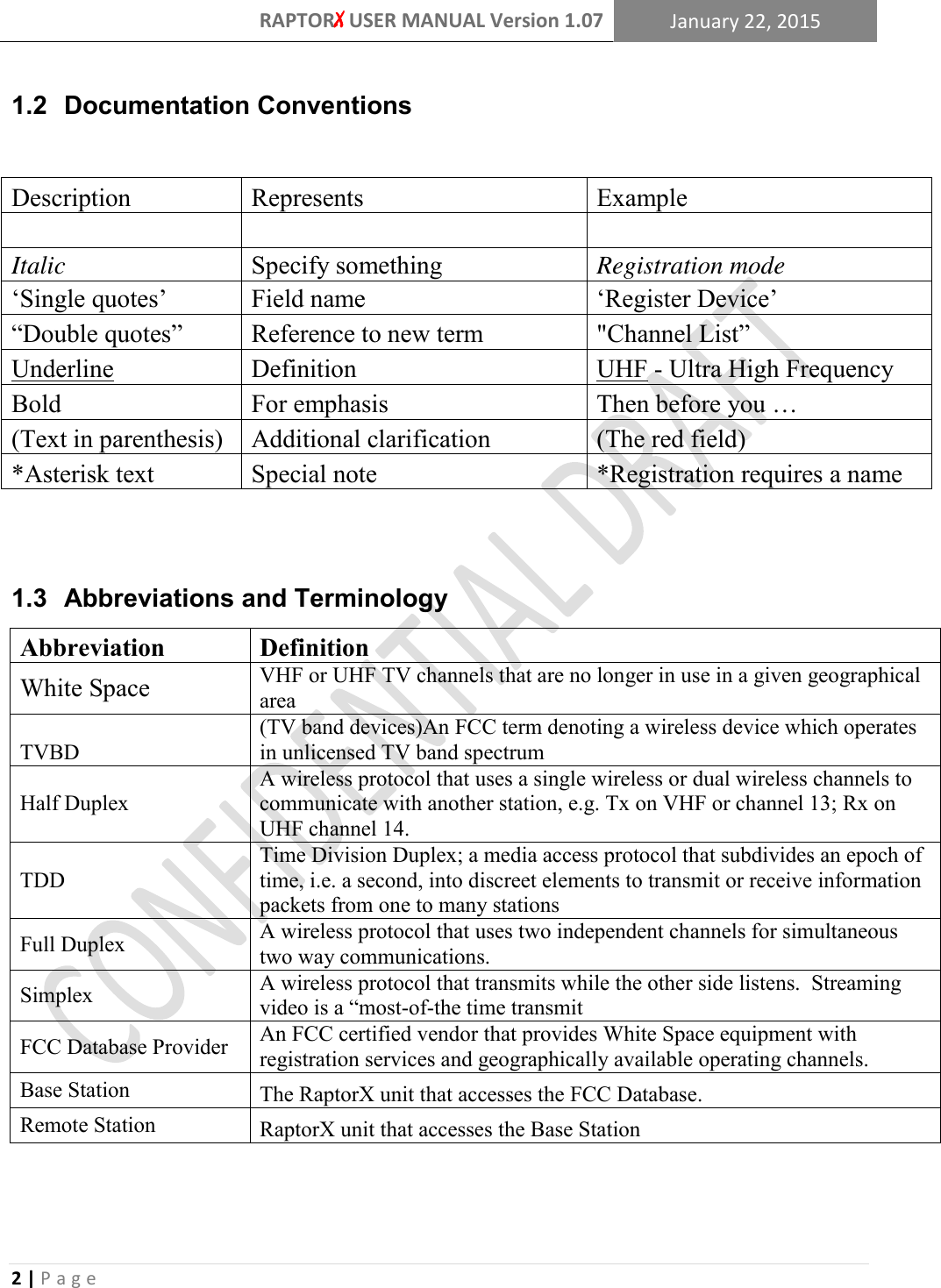
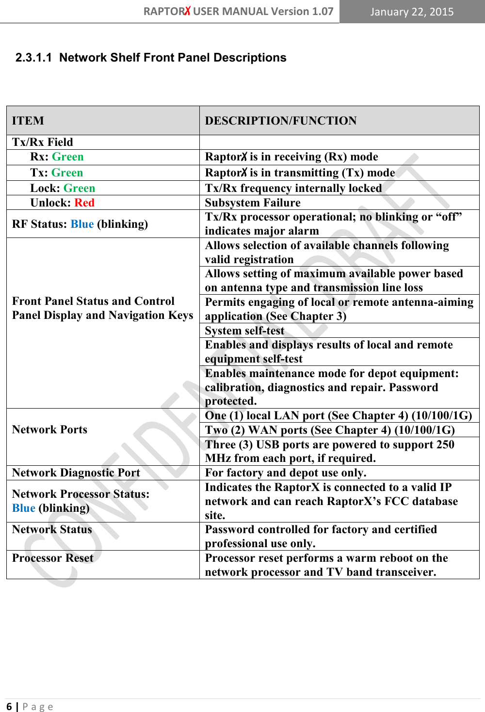
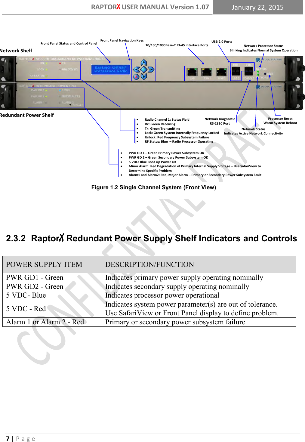
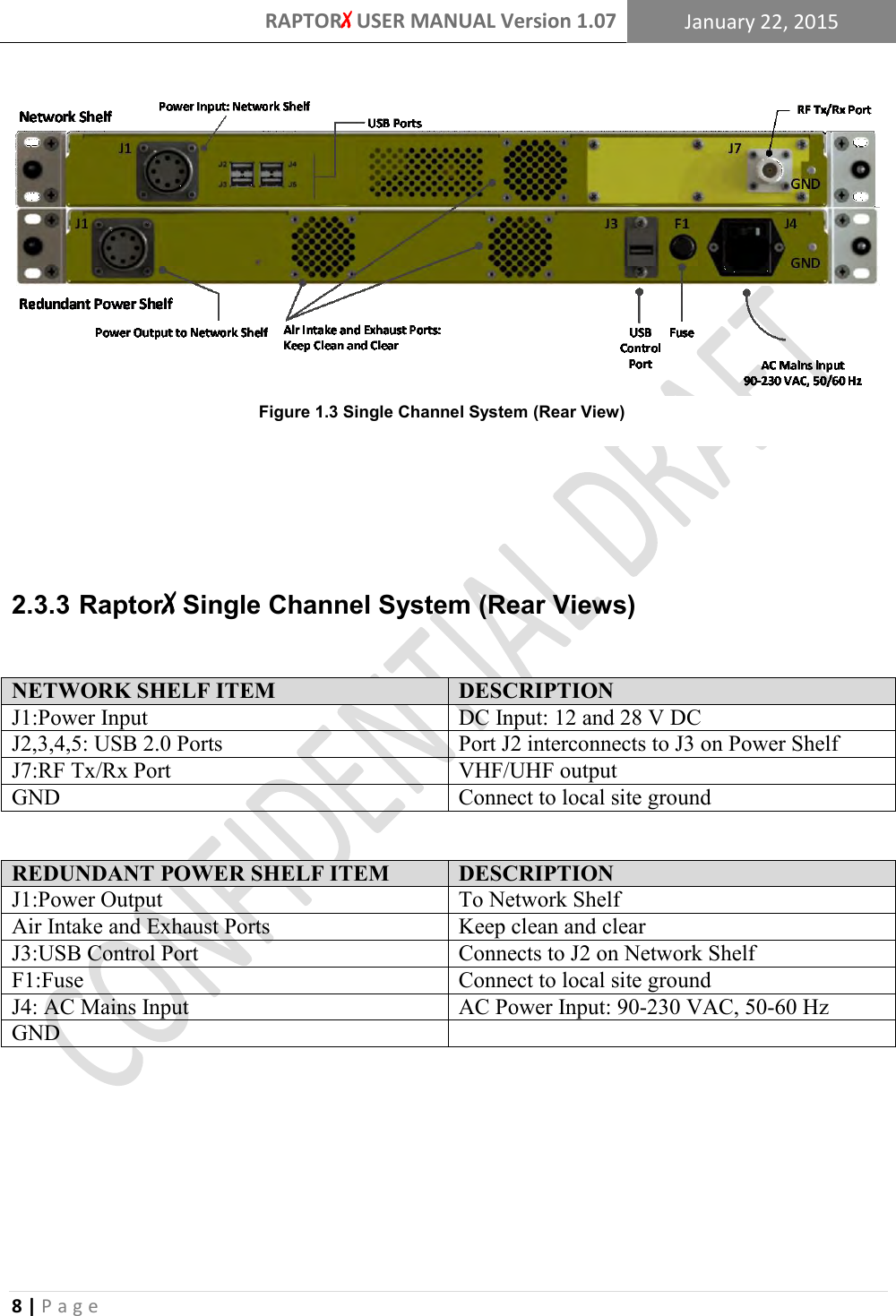
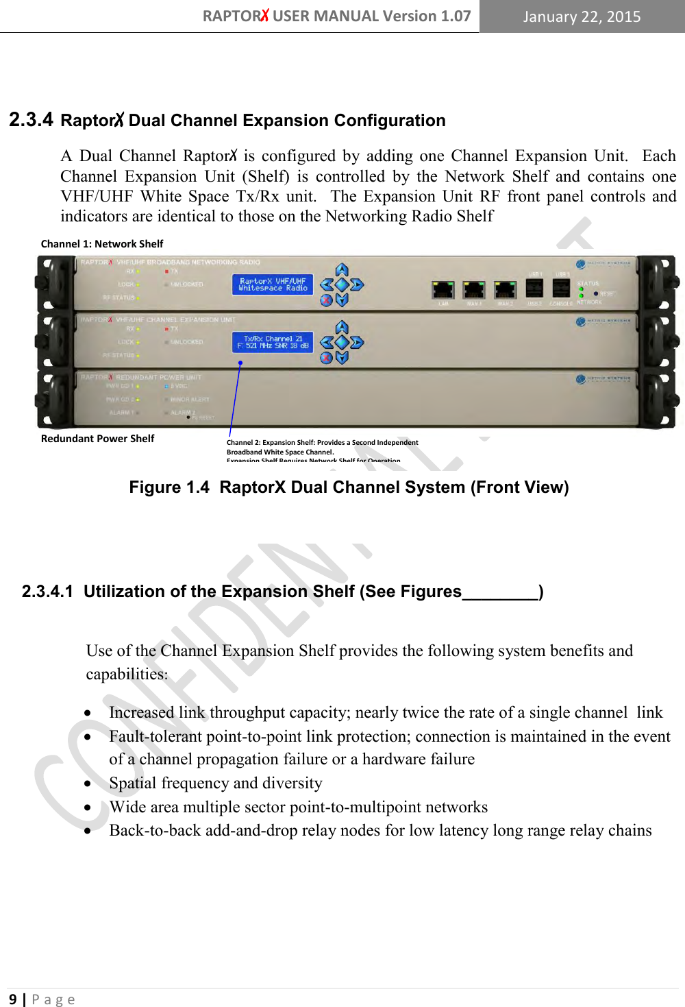
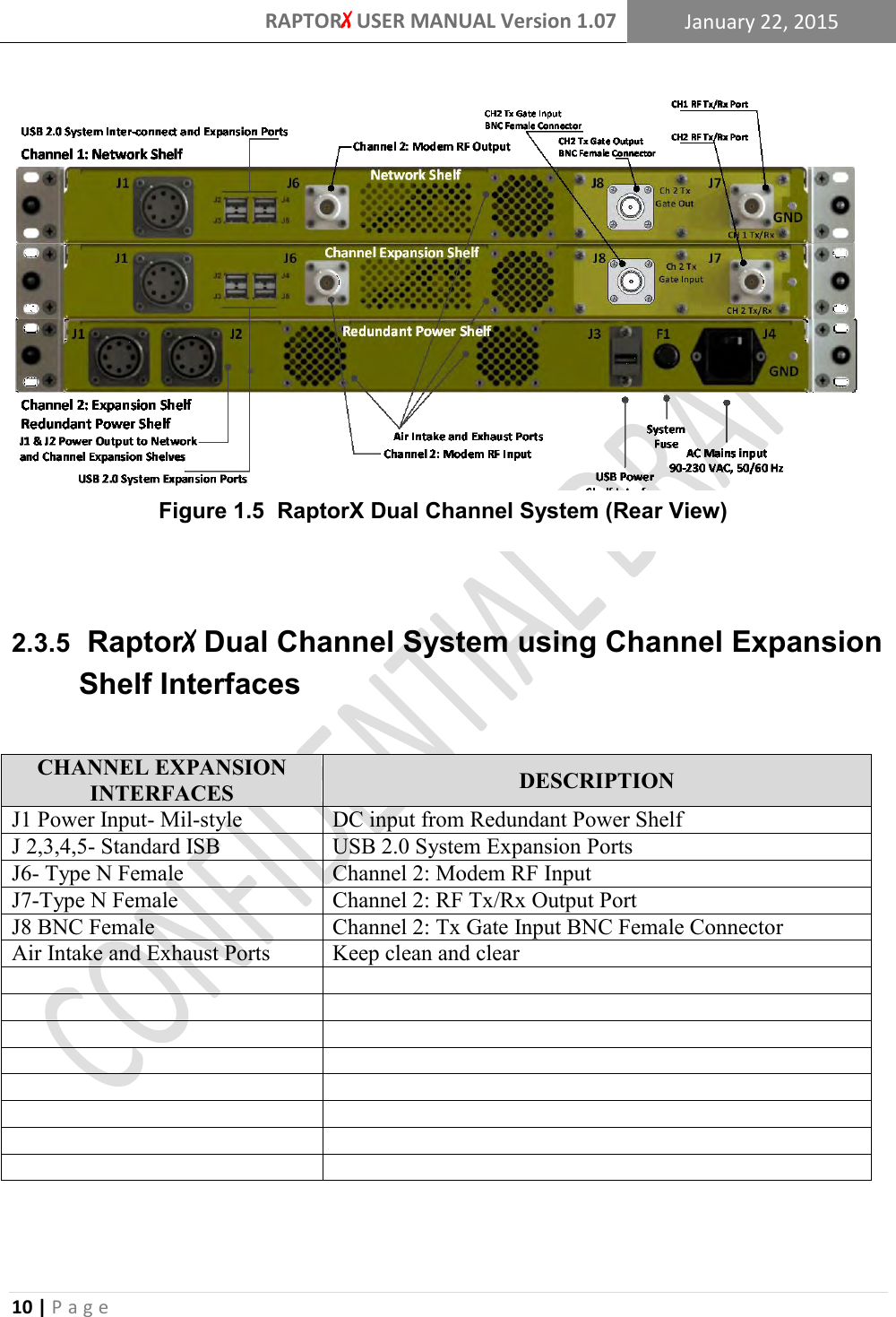
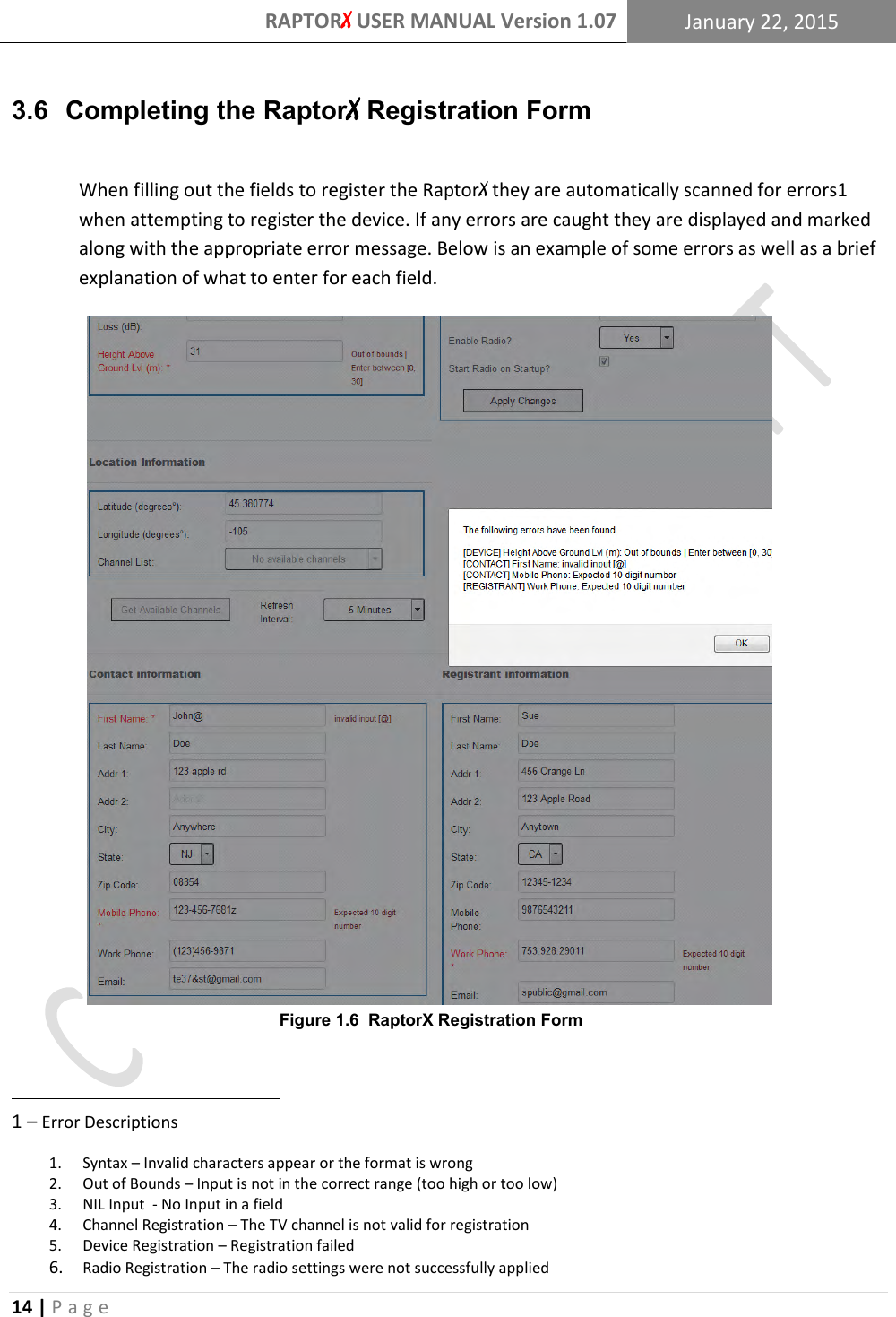
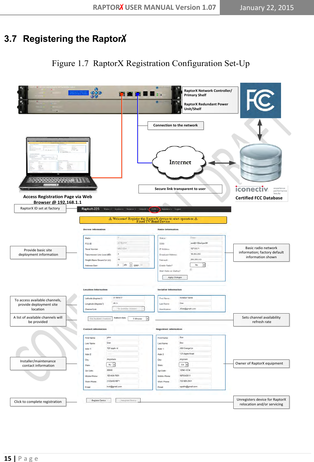
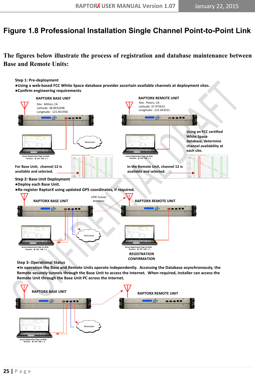
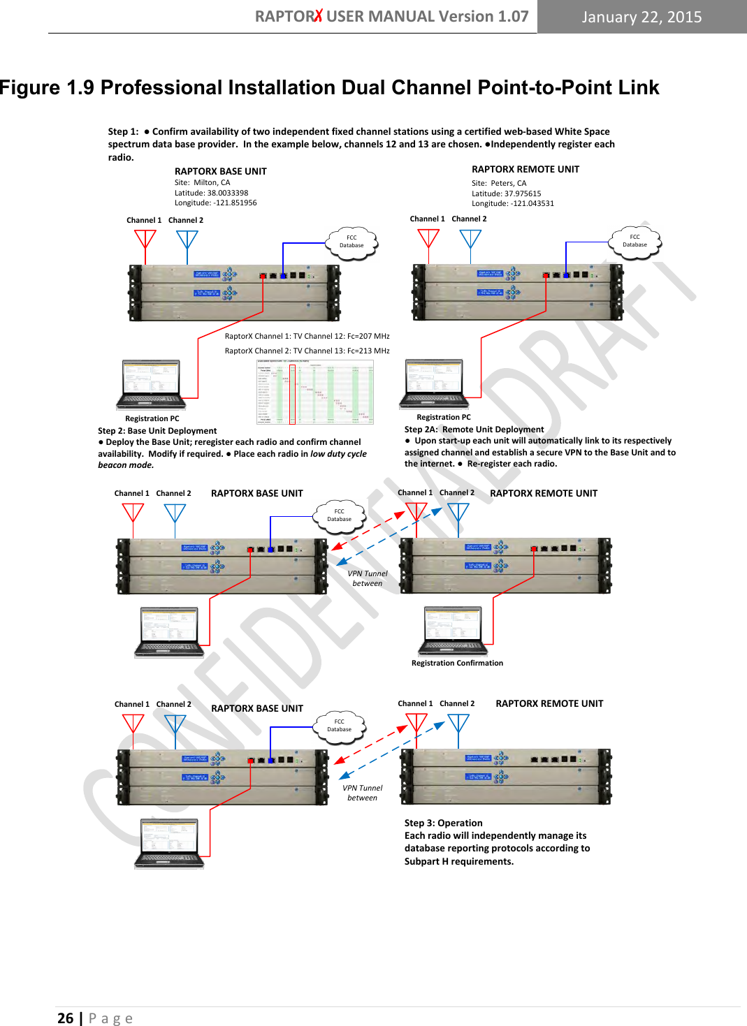
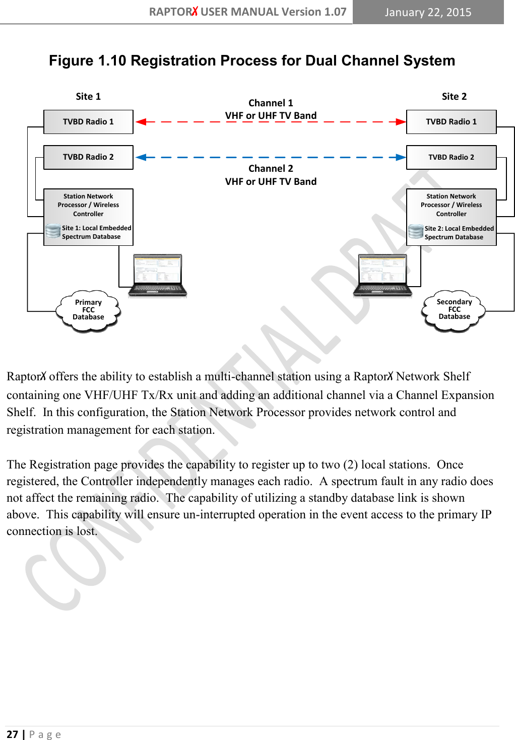
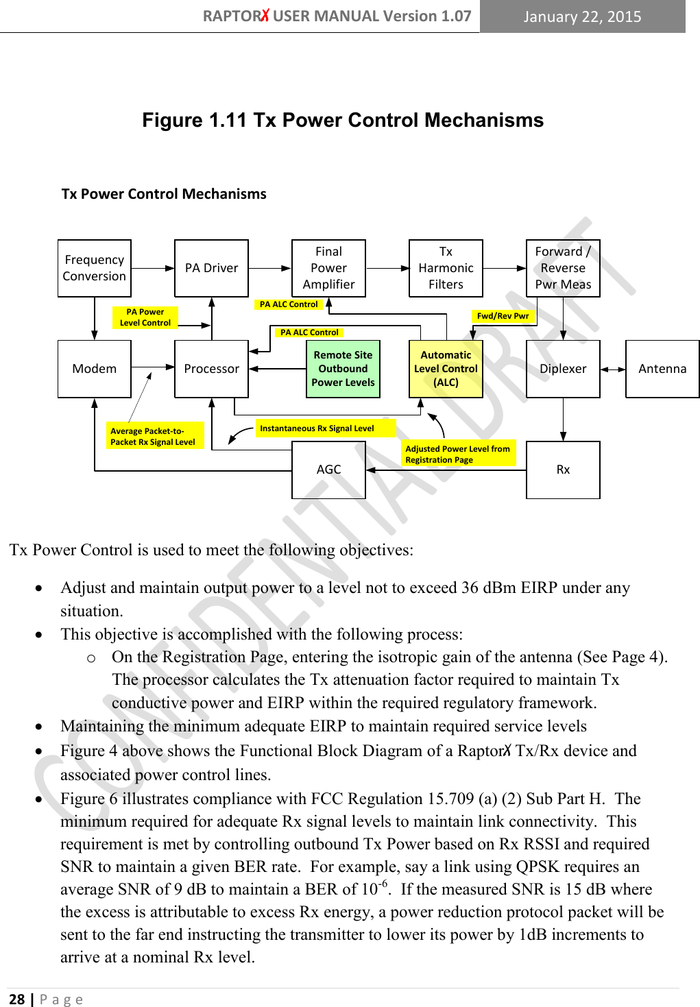
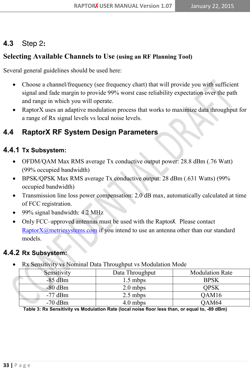
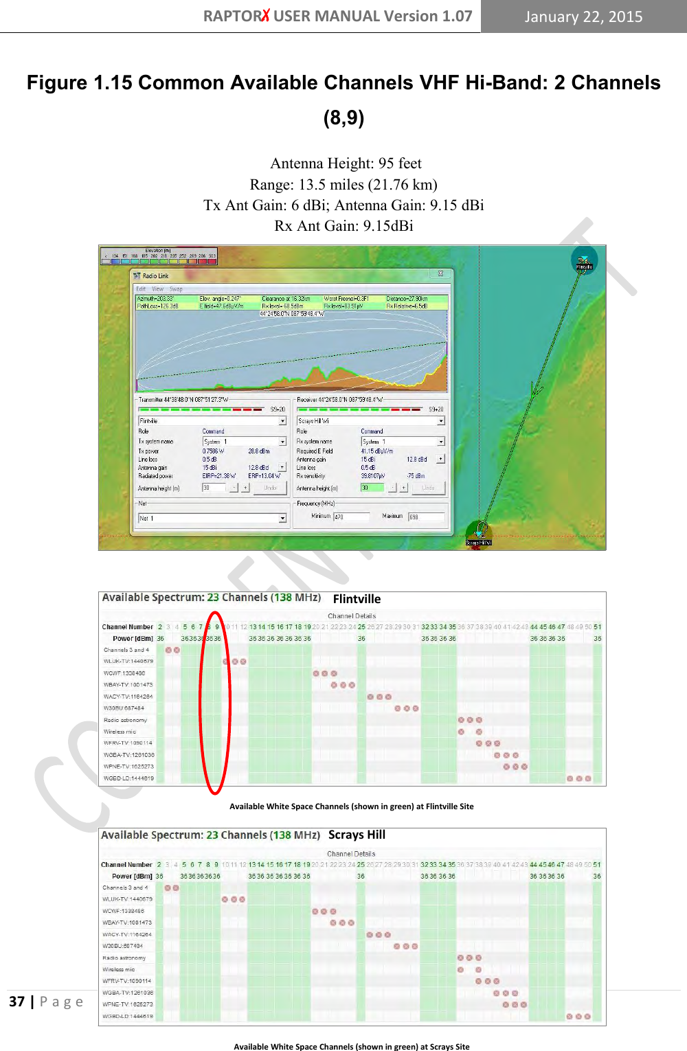
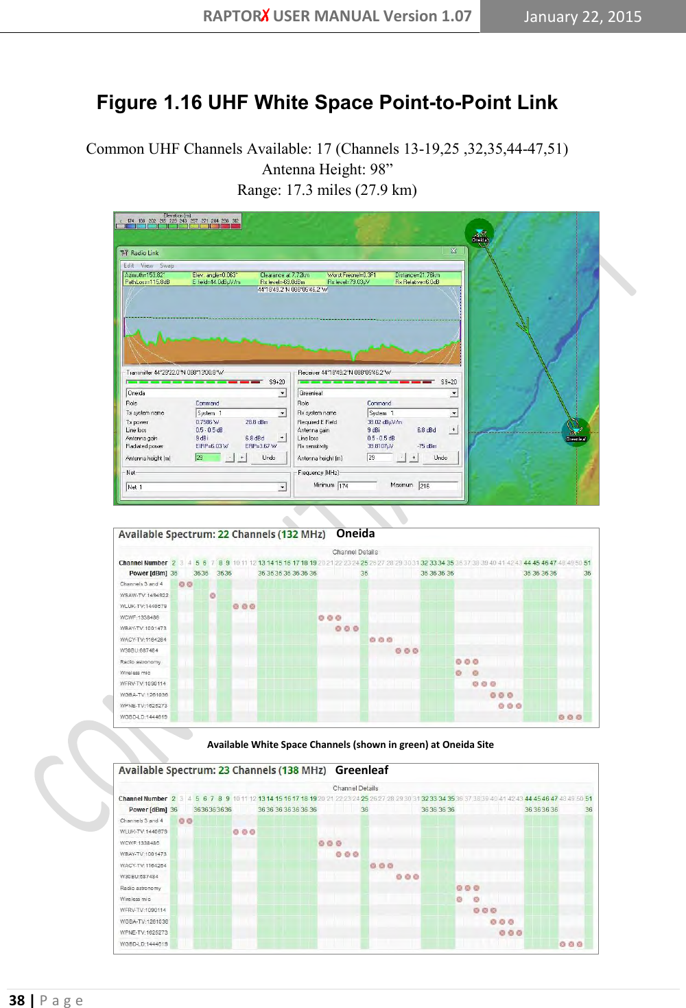
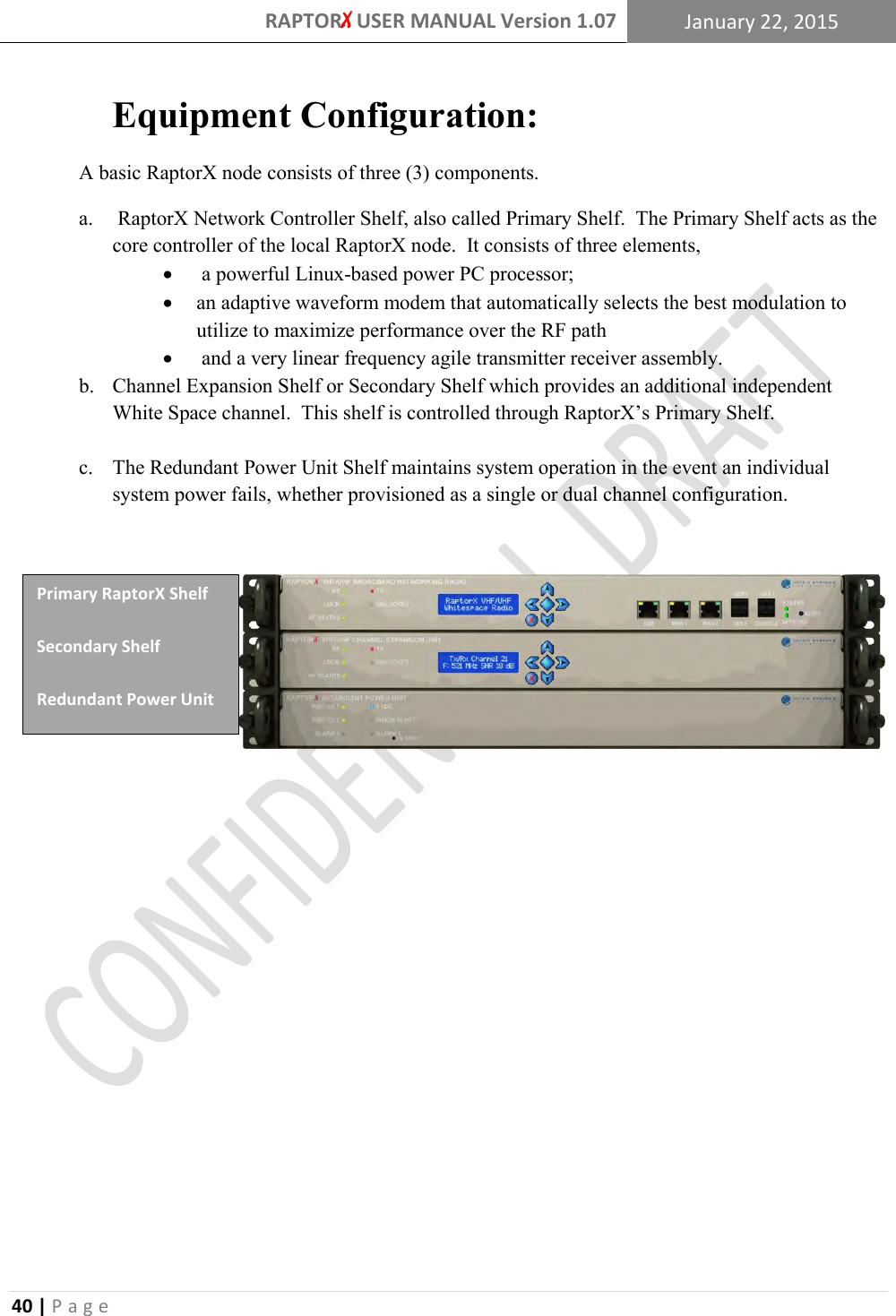
![RAPTORX USER MANUAL Version 1.07 January 22, 2015 16 | P a g e [DEVICE] 3.7.1 Radio: The device radio number | This is locked into the RaptorX at manufacture FCCID: The device FCC ID | This is locked into the RaptorX at manufacture Serial Number: The device serial number | This is locked into RaptorX at manufacture Antenna Gain: The antenna gain power (dBi/dBd) | Expected: [-15, 15] Transmission Line Loss: Measured transmission line loss (dB) | Expected: [0, 10] Antenna height above ground level (HAGL): (m) | Expected [0, 30] EIRP: The Effective Isotropic Radiated Power output | Locked into RaptorX, MAX=36 [LOCATION] 3.7.2Latitude: The latitude up to six decimal places (degrees) | Expected: [-90, 90] Longitude: The longitude up to six decimal places (degrees) | Expected: [-180, 180] Channel List: The list of available TV channels | Determined by geolocation [RADIO] 3.7.3 Status: The radio status | Will display ‘Up’ or ‘Down’ dependent on operation mode SSID: The broadcast SSID | Accepts all characters except [ ><&\”=/ ] IP Address: The radio IP Address Broadcast Address: The radio Broadcast Address Subnet mask: The radio subnet mask [CONTACT/REGISTRANT] 3.7.4*The contact form information should be that of the owner of the device. *The registrant form information should be that of the installer’s for troubleshooting. *The contact and registrant can be the same in some cases *Fill out the forms with the appropriate corresponding label information. No special cases. [MISC] 3.7.5Refresh Interval: How often the registered channel and list of available channels are checked for availability (refreshed). Recommended period: 5 minutes Enable Radio: Enable or disable the corresponding radio unit; either Radio 1 or Radio 2 Startup?: Enable or disable the corresponding radio unit when the device starts up (If enabled, the RaptorX will begin sending beacon packets to alert other RaptorX nodes operating on a common channel within the network.) Get Available Channels: Refreshes the list of available TVBD channels Register Device: Uses the information to register the RaptorX Unregister Device: Unregisters the RaptorX.](https://usermanual.wiki/METRIC-SYSTEMS/50739/User-Guide-2604977-Page-25.png)