METRIC SYSTEMS 50739 BROADBAND VHF/UHF NETWORKING RADIO SYSTEM User Manual
METRIC SYSTEMS CORPORATION BROADBAND VHF/UHF NETWORKING RADIO SYSTEM Users Manual
Users Manual

RAPTORX USER MANUAL Version 1.07
January 22, 2015
1│P a g e

RAPTORX USER MANUAL Version 1.07
January 22, 2015
iii | P a g e
FCC Regulatory Information
FCC ID: 2ABCU-50739
This device complies with part 15 of the FCC Rules. Operation is subject to the following two conditions: (1)
This device may not cause harmful interference, and (2) this device must accept any interference received,
including interference that may cause undesired operation.
Any changes or modifications not expressly approved by the party responsible for compliance could void the
user’s authority to operate the equipment.
Part 15 TV Band Device Notice
This equipment has been tested and found to comply with the rules for TV bands devices, pursuant to part 15
of the FCC rules. These rules are designed to provide reasonable protection against harmful interference.
This equipment generates, uses and can radiate radio frequency energy and, if not installed and used in
accordance with the instructions, may cause harmful interference to radio communications. If this equipment
does cause harmful interference to radio or television reception, which can be determined by turning the
equipment off and on, the user is encouraged to try to correct the interference by one or more of the following
measures:
(1) Reorient or relocate the receiving antenna.
(2) Increase the separation between the equipment and receiver.
(3) Connect the equipment into an outlet on a circuit different from that to which the receiver is connected.
(4) Consult the manufacturer, dealer or an experienced radio/TV technician for help.
Caution: Exposure to Radio Frequency Radiation.
To comply with FCC RF exposure compliance requirements, for fixed configurations, a separation distance
of at least 40 cm must be maintained between the antenna of this device and all persons.
This device must not be co-located or operating in conjunction with any other antenna or transmitter
LEGAL NOTICE
The information contained herein is the property of Metric Systems Corporation (“MSC”) and is supplied
without liability for errors or omissions. No part of this document may be reproduced, in any form,
except as authorized by contract or other written permission from the owner.
Any brand name and product names included in this manual are trademarks, registered trademarks, or
trade names of their respective holders.
The contents of this document are current as of the date of publication. MSC reserves the right to change
the contents without prior notice.
The publication of information in this document does not imply freedom from patent or other rights of
MSC or others.
2014 Metric Systems Corporation. All rights reserved. The MSC logo is a trademark of Metric Systems
Corporation. RaptorX is a trademark of Metric Systems Corporation.

RAPTORX USER MANUAL Version 1.07
January 22, 2015
iv | P a g e
OPEN-SOURCE LICENSE INFORMATION
Per the terms of your Metric Systems Limited Hardware Warranty, Software License, and RMA
Procedures Agreement with Metric Systems Corporation., certain Third Party Software may
be provided with and as part of the MSC products provided to you, and any such Third Party Software
files provided are governed by the terms of their separate Third Party Licenses, which licenses give
you at least the license rights licensed to you in the MSC End User Agreement and may give you
additional license rights as to the Third Party Software, but only with respect to the particular Third
Party Software to which the Third Party License applies.
The MSC Products may include or be bundled with some or all of the following third party software.
Copies of the copyright notices and license agreements for any or all of these may be requested by
contacting MSC support at email: info@metricsystems.com.
Open Source Code
License Agreement
Website

RAPTORX USER MANUAL Version 1.07
January 22, 2015
v | P a g e
RaptorX User Manual
Part Number 50739 Series
TABLE OF CONTENTS
LEGAL NOTICE .............................................................................................................. iii
OPEN-SOURCE LICENSE INFORMATION ...................................................................iv
List of Figures and Tables ...............................................................................................vi
Revision History ............................................................................................................. vii
Standard Hardware One (1) Year Warranty .................................................................. viii
1 Introduction ............................................................................................................... 1
1.1 Manual Overview .......................................................................................................................... 1
1.2 Documentation Conventions ........................................................................................................ 2
1.3 Abbreviations and Terminology .................................................................................................... 2
2 RaptorX Overview...................................................................................................... 3
2.1 System Benefits and Capabilities .................................................................................................. 3
2.2 Operational Capabilities ................................................................................................................ 3
2.3 The RaptorX Hardware Suite ......................................................................................................... 5
2.4 Accessing VHF/UHF TV Band Spectrum/Getting Started ............................................................ 11
3 Registration Overview ............................................................................................. 12
3.1 The RaptorX TV Band Device (TVBD) has two status modes: “Unregistered” and “Registered”. 12
3.2 Unregistered mode: .................................................................................................................... 12
3.3 Registered mode: ........................................................................................................................ 12
3.4 Radio Transmission: .................................................................................................................... 12
3.5 To change any information after registration ............................................................................. 13
3.6 Completing the RaptorX Registration Form ................................................................................ 14
3.7 Registering the RaptorX ............................................................................................................... 15
3.8 Selecting an Available Channel ................................................................................................... 18
4 RaptorX Network Design Process ........................................................................... 32
4.1 Tools Needed: ............................................................................................................................. 32

RAPTORX USER MANUAL Version 1.07
January 22, 2015
vi | P a g e
4.2 Step 1: ......................................................................................................................................... 32
4.3 Step 2: ......................................................................................................................................... 33
4.4 RaptorX RF System Design Parameters ....................................................................................... 33
4.5 Antennas: .................................................................................................................................... 35
4.6 Basic Examples: ........................................................................................................................... 36
5 Summary ................................................................................................................ 39
5.1 Provisioning RaptorX Radios: ...................................................................................................... 39
6 Technical Reference ............................................................................................... 46
6.1 RMA Procedure ........................................................................................................................... 46
List of Figures and Tables
FIGURE 1.1 SINGLE CHANNEL SYSTEM (FRONT VIEW) ILLUSTRATING USER INDICATORS, ....... 5
FIGURE 1.2 SINGLE CHANNEL SYSTEM (FRONT VIEW) ...................................................................... 7
FIGURE 1.3 SINGLE CHANNEL SYSTEM (REAR VIEW) ......................................................................... 8
FIGURE 1.4 RAPTORX DUAL CHANNEL SYSTEM (FRONT VIEW) ....................................................... 9
FIGURE 1.5 RAPTORX DUAL CHANNEL SYSTEM (REAR VIEW) ....................................................... 10
FIGURE 1.6 RAPTORX REGISTRATION FORM ..................................................................................... 14
FIGURE 1.7 RAPTORX REGISTRATION CONFIGURATION ................................................................. 14
FIGURE 1.8 PROFESSIONAL INSTALLATION SINGLE CHANNEL POINT-TO-POINT LINK ............. 14
TABLE 1 FREQUENCY RANGE/ TV CHANNELS RAPTORX REGISTRATION FORM .................... 21
FIGURE 1.9 PROFESSIONAL INSTALLATION DUAL CHANNEL POINT-TO-POINT LINK ................. 26
FIGURE 1.10 REGISTRATION PROCESS FOR DUAL CHANNEL SYSTEM ......................................... 27
FIGURE 1.11 TX POWER CONTROL MECHANISMS .............................................................................. 28
FIGURE 1.12 TEST SET UP ...................................................................................................................... 29
FIGURE 1.13 TEST PROCEDURE PARAGRAPH 15.709 (A) (2) . ERROR! BOOKMARK NOT DEFINED.
FIGURE 1.14 RAPTORX TX WAVEFORM OCCUPIED BANDWIDTH .................................................... 31
TABLE 2: EXAMPLE OF AVAILABLE CHANNELS PER GOOGLE WHITE SPACE DATABASE ... 32
TABLE 3: RX SENSITIVITY VS MODULATION RATE ........................................................................ 33
FIGURE 1.15 COMMON AVAILABLE CHANNELS VHF HI-BAND: 2 CHANNELS (8,9) ....................... 37
FIGURE 1.16 UHF WHITE SPACE POINT-TO-POINT LINK .................................................................... 38

RAPTORX USER MANUAL Version 1.07
January 22, 2015
vii | P a g e
Revision History
DATE OF
REVISION
REVISION
LETTER
DESCRIPTION OF CHANGES
PAGES CHANGED
9/30/14
Rev.1.06.2
BETA MANUAL RELEASE
3/3/15
Rev.1.07A
NEW MANUAL UPDATE
ALL

RAPTORX USER MANUAL Version 1.07
January 22, 2015
viii | P a g e
Metric Systems Corporation (MSC)
Standard Hardware One (1) Year Warranty
LIMITED WARRANTY
1. WHAT THIS WARRANTY COVERS AND FOR HOW LONG:
MSC warrants the communications product, including original equipment ("Product"), against material defects in
material and workmanship for a period of one year from the date of sale.
MSC will, at its option, and at no charge, either repair the Product (with new or reconditioned parts); replace it with
the same or equivalent Product (using new or reconditioned Product). Repaired or replaced Product is warranted for
the balance of the original applicable warranty period. All replaced parts of the Product shall become the property
of MSC.
This warranty is extended by MSC to the original end user, and is not assignable or transferable to any other party.
This is the complete warranty for the Product manufactured by MSC. MSC assumes no obligations or liability for
additions or modifications to this warranty unless made in writing and signed by an officer of MSC. Unless made in
a separate written agreement between MSC and the original end user purchaser, MSC does not warrant the
installation, maintenance or on-going service of the Product.
MSC cannot be responsible in any way for any ancillary equipment not furnished by MSC which is attached to or
used in connection with the Product, or for operation of the Product with any ancillary equipment and all such
equipment is expressly excluded from this warranty. Because each system which may use the Product is unique,
MSC disclaims liability for range, coverage, or operation of the system as a whole under this warranty.
2. GENERAL PROVISIONS:
This warranty sets forth the full extent of MSC's responsibilities regarding the Product. Repair or replacement at
MSC's option, is the exclusive remedy. THIS WARRANTY IS GIVEN IN LIEU OF ALL OTHER EXPRESS
WARRANTIES. MSC DISCLAIMS ALL OTHER WARRANTIES OR CONDITIONS, EXPRESS OR IMPLIED,
INCLUDING THE IMPLIED WARRANTIES OR CONDITIONS OF MERCHANTABILITY AND FITNESS
FOR A PARTICULAR PURPOSE. IN NO EVENT SHALL MSC BE LIABLE FOR DAMAGES IN EXCESS OF
THE PURCHASE PRICE OF THE PRODUCT, FOR ANY LOSS OF USE, LOSS OF TIME, INCONVENIENCE,
COMMERCIAL LOSS, LOST PROFITS OR SAVINGS OR OTHER INCIDENTAL, SPECIAL, INDIRECT OR
CONSEQUENTIAL DAMAGES ARISING OUT OF THE USE OR INABILITY TO USE SUCH PRODUCT, TO
THE FULL EXTENT SUCH MAY BE DISCLAIMED BY LAW.
3. HOW TO GET WARRANTY SERVICE:
Within the warranty period purchaser must notify MSC at info@metricsystems.com or 760-560-0348 to request an
RMA. Please specify the exact nature of the problem.

RAPTORX USER MANUAL Version 1.07
January 22, 2015
ix | P a g e
4. WHAT THIS WARRANTY DOES NOT COVER:
A) Defects or damage resulting from use of the Product in other than its normal and customary manner.
B) Defects or damage from Acts of War, misuse, accident, water, neglect, lightning or EMP damage, or any other
natural causes.
C) Defects or damage from improper configuration, testing, operation, maintenance, installation, alteration,
modification, or adjustment.
D) Breakage or damage to RF or IT components such as radios, transceivers, duplexers, transmission lines, routers,
hubs, switches, etc., unless caused directly by defects in material workmanship.
E) A Product subjected to unauthorized Product modifications, dis-assemblies or repairs (including, without
limitation, the addition to the Product of non-MSC supplied equipment) which adversely affect performance of
the Product or interfere with MSC's normal warranty inspection and testing of the Product to verify any
warranty claim.
F) Product which has had the serial number removed or made illegible.
G) Freight costs to and from the repair depot.
H) Illegal or unauthorized alteration of the software/firmware in the Product which prevents it from functioning in
accordance with MSC's published specifications or with the safety regulations or FCC type acceptance labeling
in effect for the Product at the time the Product was initially distributed from MSC.
I) Scratches or other cosmetic damage to Product surfaces that does not affect the operation of the Product.
J) That the software in the Product will meet the purchaser's requirements or that the operation of the software will
be uninterrupted or error-free.
K) Normal and customary wear and tear.
5. GOVERNING LAW
In the case of a Product sold in the United States, this Warranty is governed by the laws of the State of California.
6. PATENT AND SOFTWARE PROVISIONS:
MSC will defend, at its own expense, any suit brought against the end user purchaser to the extent that it is based on
a claim that the Product or its parts infringe a United States patent, and MSC will pay those costs and damages
finally awarded against the end user purchaser in any such suit which are attributable to any such claim, but such
defense and payments are conditioned on the following:
A) that MSC will be notified promptly in writing by such purchaser of any notice of such claim;
B) that MSC will have sole control of the defense of such suit and all negotiations for its settlement or compromise;
and
C) should the Product or its parts become, or in MSC's opinion be likely to become, the subject of a claim of
infringement of a United States patent, that such purchaser will permit MSC, at its option and expense, either to
procure for such purchaser the right to continue using the Product or its parts or to replace or modify the same so
that it becomes non-infringing or to grant such purchaser a credit for the Product or its parts as depreciated and
accept its return. The depreciation will be an equal amount per year over the lifetime of the Product or its parts
as established by MSC.

RAPTORX USER MANUAL Version 1.07
January 22, 2015
x | P a g e
MSC will have no liability with respect to any claim of patent infringement which is based upon the combination of
the Product or its parts furnished hereunder with software, apparatus or devices not furnished by MSC, nor will
MSC have any liability for the use of ancillary equipment or software not furnished by MSC which is attached to or
used in connection with the Product. The foregoing states the entire liability of MSC with respect to infringement of
patents by the Product or any its parts thereof.
Laws in the United States and other countries preserve for MSC certain exclusive rights for copyrighted MSC
software such as the exclusive rights to reproduce in copies and distribute copies of such MSC software. MSC
software may be used in only the Product in which the software was originally embodied and such software in such
Product may not be replaced, copied, distributed, modified in any way, or used to produce any derivative thereof.
No other use including, without limitation, alteration, modification, reproduction, distribution, or reverse
engineering of such software or exercise of rights in such MSC software is permitted. No license is granted by
implication, estoppel or otherwise under MSC patent rights or copyrights.

RAPTORX USER MANUAL Version 1.07
January 22, 2015
1│P a g e
1 Introduction
1.1 Manual Overview
This manual provides the professional telecommunications engineer or craft person with
the required information and procedures necessary to successfully design, deploy and
operate a RaptorX White Space Broadband Radio network.
This Manual is organized into four (4) chapters:
1. Overview of the RaptorX hardware, embedded capabilities and tools to allow you to
design, deploy and operate RaptorX White Space Radio equipment.
2. Spectrum Coordination and Equipment Registration. This section will show how to
determine what TV band channels are available to support your network application
and how each RaptorX is registered with the FCC via RaptorX’s certified database
supplier to operate on available channels
3. System/Network Design. This segment of the Manual provides the necessary
technical and practical information to successfully design, deploy and operate
multiple RaptorX Radio nodes in various network configurations.
4. Technical Reference section addresses system operations and maintenance
procedures.

RAPTORX USER MANUAL Version 1.07
January 22, 2015
2 | P a g e
1.2 Documentation Conventions
1.3 Abbreviations and Terminology
Abbreviation
Definition
White Space
VHF or UHF TV channels that are no longer in use in a given geographical
area
TVBD
(TV band devices)An FCC term denoting a wireless device which operates
in unlicensed TV band spectrum
Half Duplex
A wireless protocol that uses a single wireless or dual wireless channels to
communicate with another station, e.g. Tx on VHF or channel 13; Rx on
UHF channel 14.
TDD
Time Division Duplex; a media access protocol that subdivides an epoch of
time, i.e. a second, into discreet elements to transmit or receive information
packets from one to many stations
Full Duplex
A wireless protocol that uses two independent channels for simultaneous
two way communications.
Simplex
A wireless protocol that transmits while the other side listens. Streaming
video is a “most-of-the time transmit
FCC Database Provider
An FCC certified vendor that provides White Space equipment with
registration services and geographically available operating channels.
Base Station
The RaptorX unit that accesses the FCC Database.
Remote Station
RaptorX unit that accesses the Base Station
Description
Represents
Example
Italic
Specify something
Registration mode
‘Single quotes’
Field name
‘Register Device’
“Double quotes”
Reference to new term
"Channel List”
Underline
Definition
UHF - Ultra High Frequency
Bold
For emphasis
Then before you …
(Text in parenthesis)
Additional clarification
(The red field)
*Asterisk text
Special note
*Registration requires a name

RAPTORX USER MANUAL Version 1.07
January 22, 2015
3 | P a g e
2 RaptorX Overview
RaptorX is an unlicensed broadband half-duplex Tx/Rx Networking Radio System
operating in high VHF TV channels 7-13 (174 MHz -216 MHz) and authorized UHF
channels 14-35 (470 MHz-599 MHz) and UHF channels 39-51 (620-698 MHz) bands. The
primary technical mission of the RaptorX suite is to support industrial, commercial, and
governmental backhaul and edge network transport applications. The RaptorX features an
adaptive suite of robust transmit modulation formats along with full legal conducted RF
power output capability (27.8 dBm) to take full advantage of locally available TV band
spectrum. MSC offers a variety of antenna types to support Omni, Sector and Directional
applications. With the appropriate antenna the maximum FCC EIRP transmit power of 36
dBm (4 Watts) is available. While in the Rx mode, higher gain antennas can provide
additional passive gain to extend range and coverage area.
2.1 System Benefits and Capabilities
Extended range, beyond horizon operation, and superior in-structure operation
Easily integrates with existing public and private wireless systems
Provides new and enhanced revenue opportunities to service and venue
operators.
2.2 Operational Capabilities
Maximum legal EIRP support for both VHF high band channels (7 to 13) and
UHF channels (14 to 35 and 39 to 51);
High system margin supports VHF and UHF operation to 20+ miles;
Fixed or dynamically-adaptable payload rates of 1 to 6 mbps;
Half-duplex, single frequency or dual frequency operations;
Tx/Rx diversity advantage: separate Tx and Rx antenna options for extended
range and custom coverage requirements;
SafariView: RaptorX’s integrated HTML-based systems Operations,
Administration and Maintenance application is accessible via front Ethernet
ports or short range secure wireless connection using a standard web browser
(Mozilla, Safari, Apple 4, Internet Explorer);
User-configurable to support:● multiple network and link topologies;● single
channel point-to-point,● multiple-channel point-to-point,● chained point-to-
point relay links,● ad hoc-based mesh nets and ●point-to-multipoint;
Bandwidth scalable – two or more available White Space channels can be
bonded (channel aggregation) to increase link payload capacity and provide
high-link reliability via spatial diversity;
Two-channel MIMO operation provides superior operation in urban or natural
clutter environments.

RAPTORX USER MANUAL Version 1.07
January 22, 2015
4 | P a g e
Optional System Features 2.2.1
FEATURES
DESCRIPTION
Separate ports
Provisions for separate Tx and Rx ports enabling the RaptorX to operate in a
MIMO configuration (1 x 1) for enhanced operation in a cluttered environment
(urban, forested, refineries, etc.)
System Clock
Provision for external high stability system clock used for single frequency
network operation
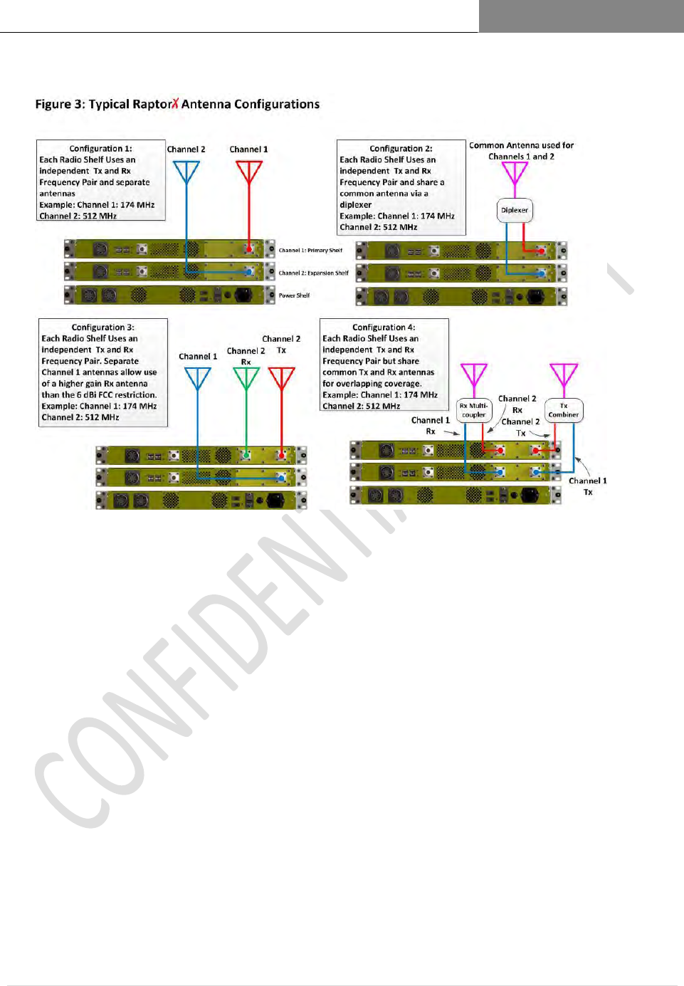
Antenna-
common
A common antenna will serve multiple RaptorXs in a channel aggregation
configuration serving industrial wireless internet service provider
(WISP)applications
Antenna-
separate
Separate Tx and Rx antennas support the RaptorX capability for spatial and
frequency diversity configuration useful for extending range, shaping coverage
footprints and increasing overall system reliability.
RAPTORX USER MANUAL Version 1.07
January 22, 2015
5 | P a g e
2.3 The RaptorX Hardware Suite
The basic RaptorX Hardware Suite consists of three (3) purpose-specific component
shelves which are user-configured to support single or dual-channel White Space
operation:
Network Shelf – common to single and dual channel configurations (See Figure 1.0)
Channel Expansion Shelf – provides an additional VHF/UHF Channel (See Figure
3.0)
Redundant Power Shelf (See Figure 1.0) provides power to network and expansion
shelves.
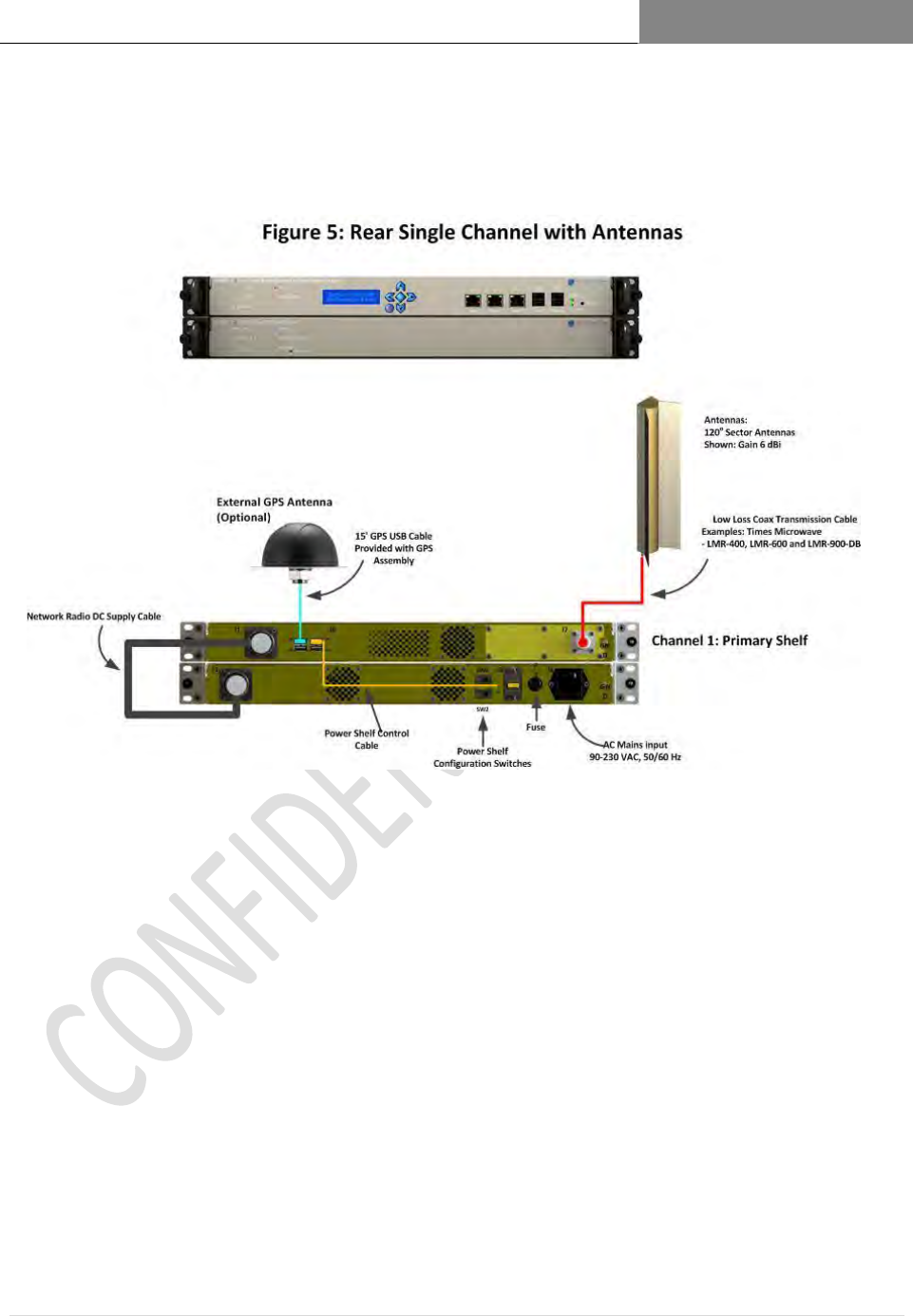
A RaptorX Single White Space Channel Configuration includes one 2.3.1
(1) RaptorX Network Shelf contains the local network processor and a single channel
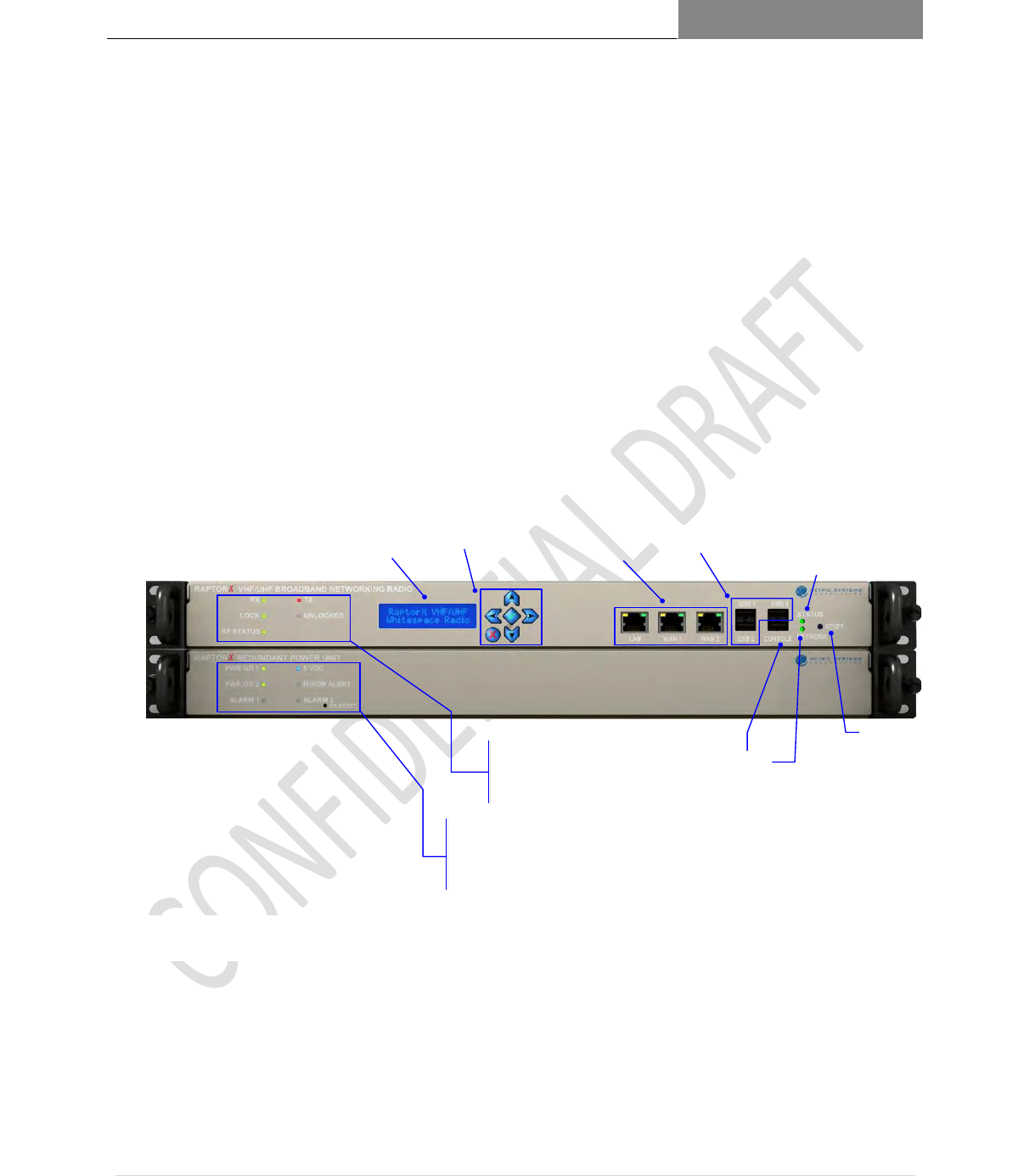
White Space VHF/UHF broadband radio. Figure 1.0 below shows user indicators,
controls and physical interfaces. Figure 2.0 shows the rear view of a single channel
stack. Figure_____ shows a basic site single channel configuration.
The front view ergonomics of all RaptorX equipment are designed to provide the user and
installer with the minimum required indicators and controls to monitor, operate and maintain
system operation following equipment registration.
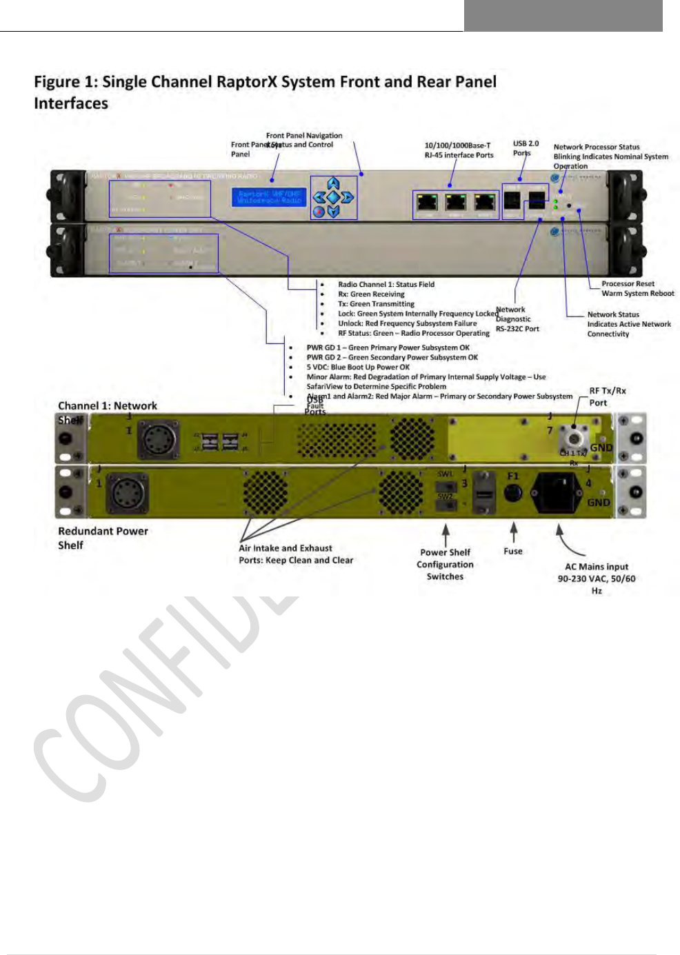
Figure 1.1 Single Channel System (Front View) illustrating user indicators, controls and physical interfaces.
Network Processor Status
Blinking Indicates Normal System Operation
Processor Reset
Warm System Reboot
Network Status
Indicates Active Network Connectivity
Radio Channel 1: Status Field
Rx: Green Receiving
Tx: Green Transmitting
Lock: Green System Internally Frequency Locked
Unlock: Red Frequency Subsystem Failure
RF Status: Blue – Radio Processor Operating
PWR GD 1 – Green Primary Power Subsystem OK
PWR GD 2 – Green Secondary Power Subsystem OK
5 VDC: Blue Boot Up Power OK
Minor Alarm: Red Degradation of Primary Internal Supply Voltage – Use SafariView to
Determine Specific Problem
Alarm1 and Alarm2: Red, Major Alarm – Primary or Secondary Power Subsystem Fault
Front Panel Navigation Keys
Front Panel Status and Control Panel
Network Diagnostic
RS-232C Port
USB 2.0 Ports
10/100/1000Base-T RJ-45 interface Ports
Redundant Power Shelf
Network Shelf

RAPTORX USER MANUAL Version 1.07
January 22, 2015
6 | P a g e
2.3.1.1 Network Shelf Front Panel Descriptions
ITEM
DESCRIPTION/FUNCTION
Tx/Rx Field
Rx: Green
RaptorX is in receiving (Rx) mode
Tx: Green
RaptorX is in transmitting (Tx) mode
Lock: Green
Tx/Rx frequency internally locked
Unlock: Red
Subsystem Failure
RF Status: Blue (blinking)
Tx/Rx processor operational; no blinking or “off”
indicates major alarm
Front Panel Status and Control
Panel Display and Navigation Keys
Allows selection of available channels following
valid registration
Allows setting of maximum available power based
on antenna type and transmission line loss
Permits engaging of local or remote antenna-aiming
application (See Chapter 3)
System self-test
Enables and displays results of local and remote
equipment self-test
Enables maintenance mode for depot equipment:
calibration, diagnostics and repair. Password
protected.
Network Ports
One (1) local LAN port (See Chapter 4) (10/100/1G)
Two (2) WAN ports (See Chapter 4) (10/100/1G)
Three (3) USB ports are powered to support 250
MHz from each port, if required.
Network Diagnostic Port
For factory and depot use only.
Network Processor Status:
Blue (blinking)
Indicates the RaptorX is connected to a valid IP
network and can reach RaptorX’s FCC database
site.
Network Status
Password controlled for factory and certified
professional use only.
Processor Reset
Processor reset performs a warm reboot on the
network processor and TV band transceiver.
RAPTORX USER MANUAL Version 1.07
January 22, 2015
7 | P a g e
RaptorX Redundant Power Supply Shelf Indicators and Controls 2.3.2
POWER SUPPLY ITEM
DESCRIPTION/FUNCTION
PWR GD1 - Green
Indicates primary power supply operating nominally
PWR GD2 - Green
Indicates secondary supply operating nominally
5 VDC- Blue
Indicates processor power operational
5 VDC - Red
Indicates system power parameter(s) are out of tolerance.
Use SafariView or Front Panel display to define problem.
Alarm 1 or Alarm 2 - Red
Primary or secondary power subsystem failure
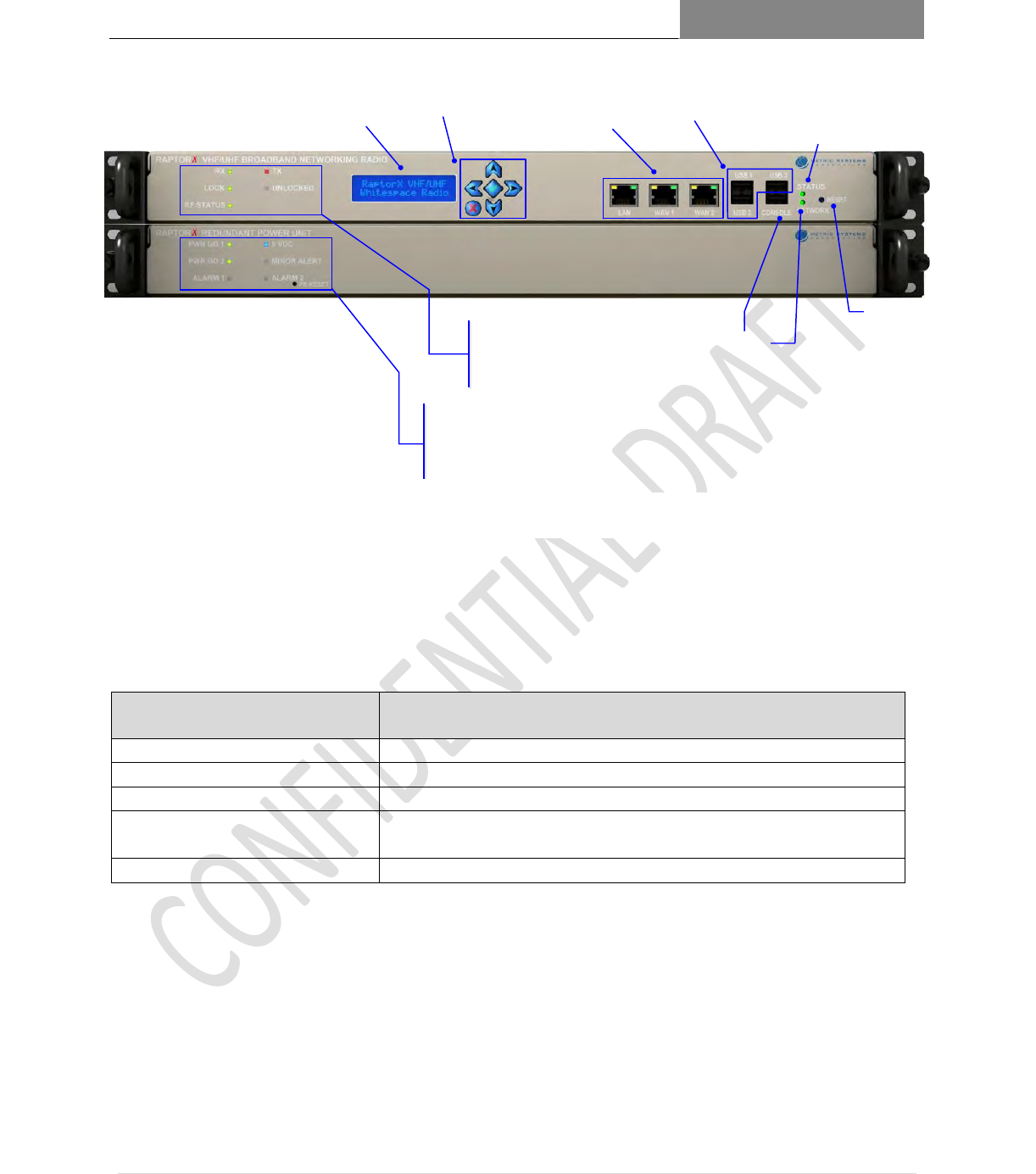
Figure 1.2 Single Channel System (Front View)
Network Processor Status
Blinking Indicates Normal System Operation
Processor Reset
Warm System Reboot
Network Status
Indicates Active Network Connectivity
Radio Channel 1: Status Field
Rx: Green Receiving
Tx: Green Transmitting
Lock: Green System Internally Frequency Locked
Unlock: Red Frequency Subsystem Failure
RF Status: Blue – Radio Processor Operating
PWR GD 1 – Green Primary Power Subsystem OK
PWR GD 2 – Green Secondary Power Subsystem OK
5 VDC: Blue Boot Up Power OK
Minor Alarm: Red Degradation of Primary Internal Supply Voltage – Use SafariView to
Determine Specific Problem
Alarm1 and Alarm2: Red, Major Alarm – Primary or Secondary Power Subsystem Fault
Front Panel Navigation Keys
Front Panel Status and Control Panel
Network Diagnostic
RS-232C Port
USB 2.0 Ports
10/100/1000Base-T RJ-45 interface Ports
Redundant Power Shelf
Network Shelf
RAPTORX USER MANUAL Version 1.07
January 22, 2015
8 | P a g e
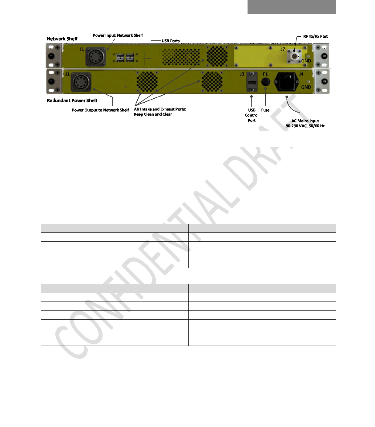
RaptorX Single Channel System (Rear Views) 2.3.3
NETWORK SHELF ITEM
DESCRIPTION
J1:Power Input
DC Input: 12 and 28 V DC
J2,3,4,5: USB 2.0 Ports
Port J2 interconnects to J3 on Power Shelf
J7:RF Tx/Rx Port
VHF/UHF output
GND
Connect to local site ground
REDUNDANT POWER SHELF ITEM
DESCRIPTION
J1:Power Output
To Network Shelf
Air Intake and Exhaust Ports
Keep clean and clear
J3:USB Control Port
Connects to J2 on Network Shelf
F1:Fuse
Connect to local site ground
J4: AC Mains Input
AC Power Input: 90-230 VAC, 50-60 Hz
GND
Figure 1.3 Single Channel System (Rear View)
RAPTORX USER MANUAL Version 1.07
January 22, 2015
9 | P a g e
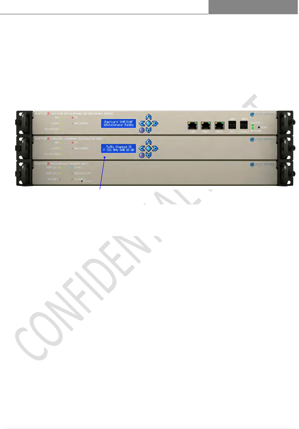
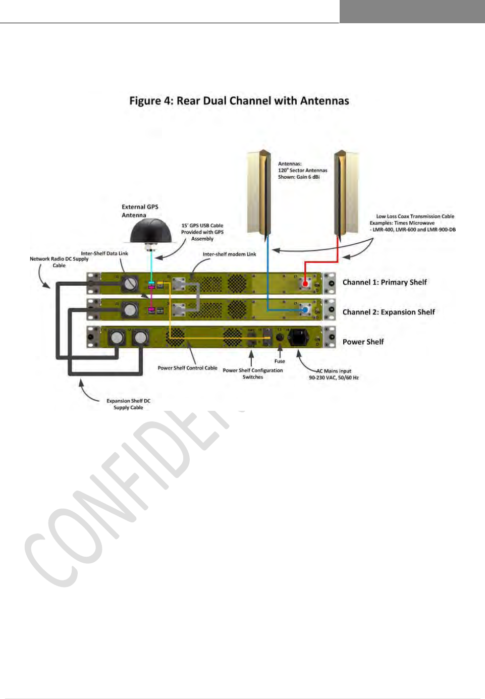
RaptorX Dual Channel Expansion Configuration 2.3.4
A Dual Channel RaptorX is configured by adding one Channel Expansion Unit. Each
Channel Expansion Unit (Shelf) is controlled by the Network Shelf and contains one
VHF/UHF White Space Tx/Rx unit. The Expansion Unit RF front panel controls and
indicators are identical to those on the Networking Radio Shelf
2.3.4.1 Utilization of the Expansion Shelf (See Figures________)
Use of the Channel Expansion Shelf provides the following system benefits and
capabilities:
Increased link throughput capacity; nearly twice the rate of a single channel link
Fault-tolerant point-to-point link protection; connection is maintained in the event
of a channel propagation failure or a hardware failure
Spatial frequency and diversity
Wide area multiple sector point-to-multipoint networks
Back-to-back add-and-drop relay nodes for low latency long range relay chains
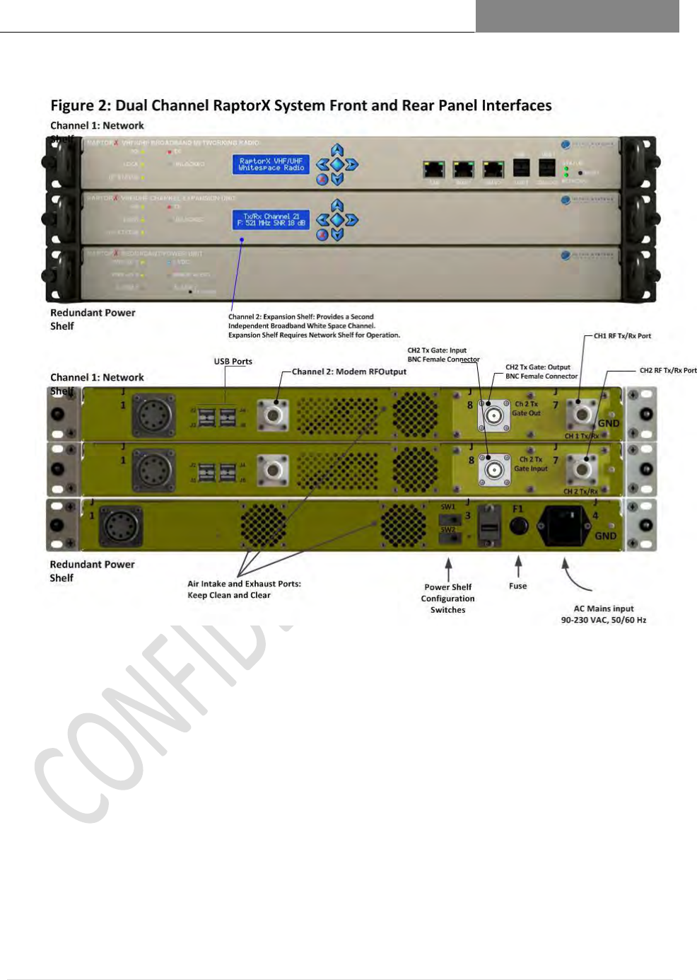
Figure 1.4 RaptorX Dual Channel System (Front View)
Channel 2: Expansion Shelf: Provides a Second Independent
Broadband White Space Channel.
Expansion Shelf Requires Network Shelf for Operation.
Redundant Power Shelf
Channel 1: Network Shelf
RAPTORX USER MANUAL Version 1.07
January 22, 2015
10 | P a g e
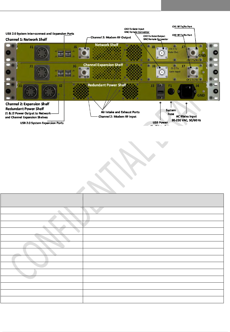
RaptorX Dual Channel System using Channel Expansion 2.3.5
Shelf Interfaces
CHANNEL EXPANSION
INTERFACES
DESCRIPTION
J1 Power Input- Mil-style
DC input from Redundant Power Shelf
J 2,3,4,5- Standard ISB
USB 2.0 System Expansion Ports
J6- Type N Female
Channel 2: Modem RF Input
J7-Type N Female
Channel 2: RF Tx/Rx Output Port
J8 BNC Female
Channel 2: Tx Gate Input BNC Female Connector
Air Intake and Exhaust Ports
Keep clean and clear
Figure 1.5 RaptorX Dual Channel System (Rear View)

RAPTORX USER MANUAL Version 1.07
January 22, 2015
11 | P a g e
2.4 Accessing VHF/UHF TV Band Spectrum/Getting Started
See Figure 5.Registering the RaptorX, which shows the registration configuration of a
RaptorX connected to the internet.
The RaptorX only becomes operational when successfully registered with the RaptorX’s
designated FCC certified database provider, IConnectiv. (http://iconectiv.com/spectrum-
mgmt/white-spaces/index.html)
Each RaptorX has been registered for two (2) years with Iconnectiv.
It is the operator’s responsibility to assure continued registration, either directly with a
certified database provider or through an MSC Service Plan.
2.4.1.1 To access the Registration page insert the IP address: 192.168.1.1 into your web
browser/URL line.
2.4.1.2 Insert required device and location information. Click Registration.
2.4.1.3 Upon a successful registration a list of available White Space channels will be
returned.
2.4.1.4 Select the appropriate TV channel to complete registration and activate the Tx
subsystem of the RaptorX.
2.4.1.5 The remaining sections will describe in detail the Registration process. The RaptorX
will automatically validate and re-register the unit every 24 hours.

RAPTORX USER MANUAL Version 1.07
January 22, 2015
12 | P a g e
3 Registration Overview
3.1 The RaptorX TV Band Device (TVBD) has two status modes:
“Unregistered” and “Registered”.
When valid registration settings are detected 3.1.1
an attempt is made to load the configuration. Upon successfully loading, an
automatic check is performed to determine the mode (see definitions below) and
that the appropriate form fields are displayed for the proper mode.
3.2 Unregistered mode:
All fields (excluding address 2) under Device, Location, Contact, and Registrant must be
completed with valid information (see pg. 7). Once completed the device must be
registered by clicking the ‘Register Device’ button. If an error is caught registration will
fail and a notification with the appropriate error(s) will be shown. In the event of an error
the device will stand-by for correct input before successfully switching to registered
mode.
3.3 Registered mode:
Upon successful registration, a list of available white space channels is returned in the
“Channel List” drop-down menu and the device prompts to select a channel. When a
channel has been selected the device does an additional check with the FCC database to
ensure it is still available and proceeds with the channel registration. At any point the user
may choose to refresh the ‘Available Channel’ list or ‘Unregister’ the device by clicking
the desired button.
3.4 Radio Transmission:
After successfully registering a radio to a channel frequency the final step is to enable radio
transmission. To do so, fill out all input fields under the Radio Information and set Enable
Radio to the Yes Option. If the device should enable the radio on startup, check the

RAPTORX USER MANUAL Version 1.07
January 22, 2015
13 | P a g e
appropriate box as well. Click the ‘Apply Changes’ button to commence RaptorX radio
operations.
3.5 To change any information after registration
the device must first be in the unregistered state. To do so, simply click the Unregister
button.
RAPTORX USER MANUAL Version 1.07
January 22, 2015
14 | P a g e
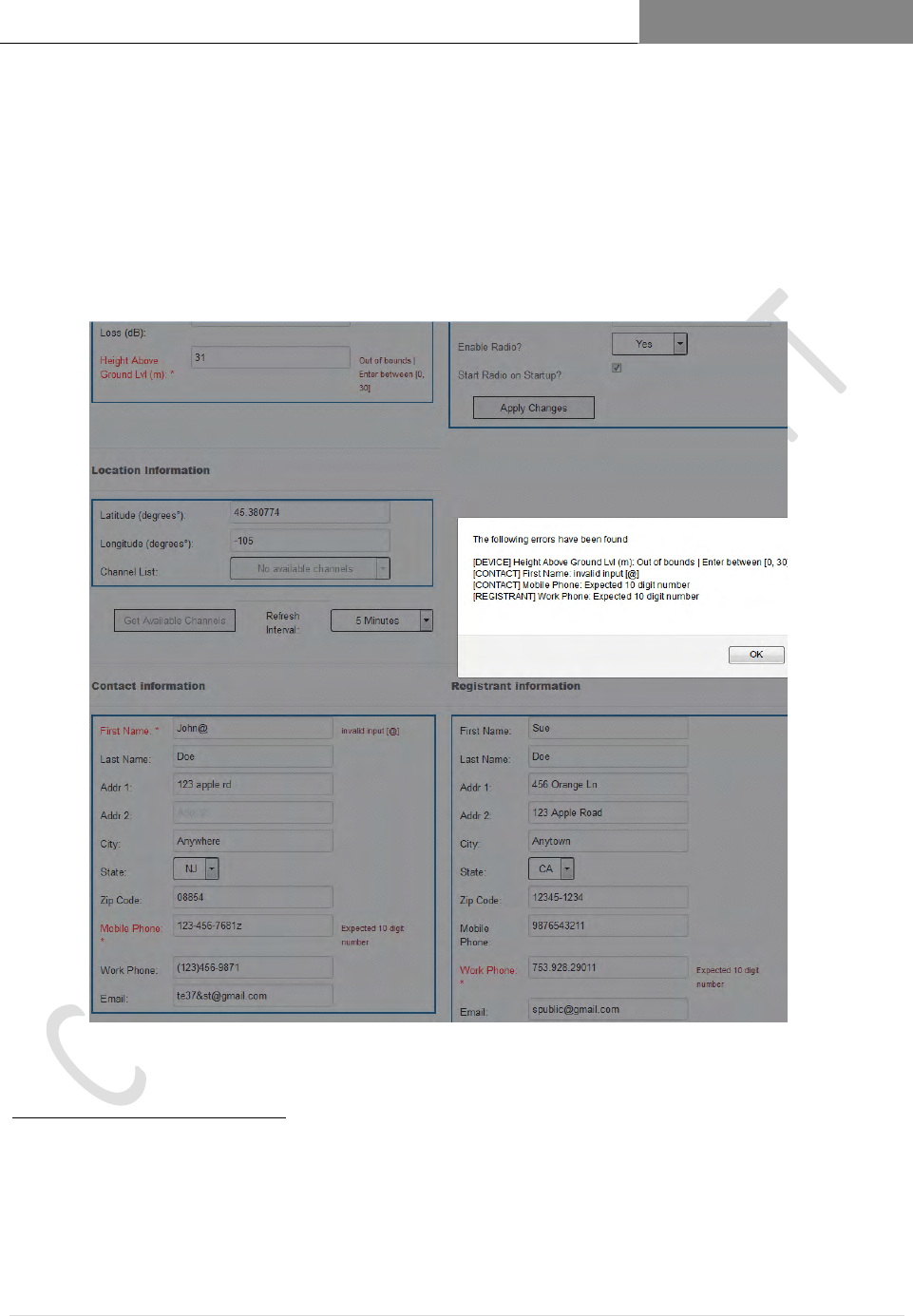
3.6 Completing the RaptorX Registration Form
When filling out the fields to register the RaptorX they are automatically scanned for errors
1
when attempting to register the device. If any errors are caught they are displayed and marked
along with the appropriate error message. Below is an example of some errors as well as a brief
explanation of what to enter for each field.
1 – Error Descriptions
1. Syntax – Invalid characters appear or the format is wrong
2. Out of Bounds – Input is not in the correct range (too high or too low)
3. NIL Input - No Input in a field
4. Channel Registration – The TV channel is not valid for registration
5. Device Registration – Registration failed
6. Radio Registration – The radio settings were not successfully applied
Figure 1.6 RaptorX Registration Form
RAPTORX USER MANUAL Version 1.07
January 22, 2015
15 | P a g e
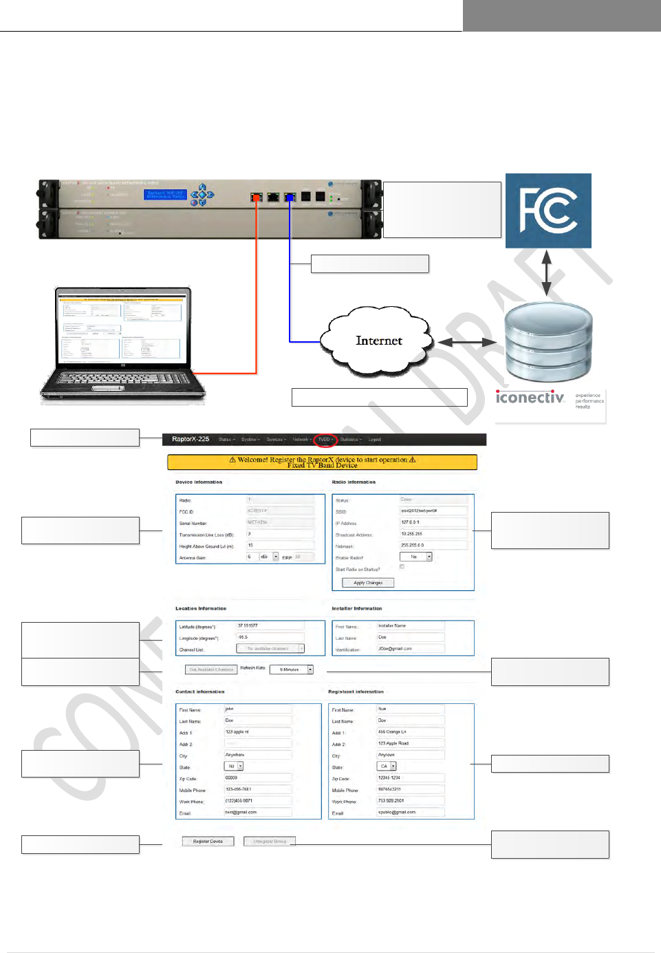
3.7 Registering the RaptorX
Certified FCC Database
Access Registration Page via Web
Browser @ 192.168.1.1
Installer/maintenance
contact information
To access available channels,
provide deployment site
location
Provide basic site
deployment information
Click to complete registration
A list of available channels will
be provided
Figure 1.7 RaptorX Registration Configuration Set-Up
RaptorX ID set at factory
RaptorX Network Controller/
Primary Shelf
RaptorX Redundant Power
Unit/Shelf
Connection to the network
Secure link transparent to user
Basic radio network
information; factory default
information shown
Sets channel availability
refresh rate
Owner of RaptorX equipment
Unregisters device for RaptorX
relocation and/or servicing

RAPTORX USER MANUAL Version 1.07
January 22, 2015
16 | P a g e
[DEVICE] 3.7.1
Radio: The device radio number | This is locked into the RaptorX at manufacture
FCCID: The device FCC ID | This is locked into the RaptorX at manufacture
Serial Number: The device serial number | This is locked into RaptorX at manufacture
Antenna Gain: The antenna gain power (dBi/dBd) | Expected: [-15, 15]
Transmission Line Loss: Measured transmission line loss (dB) | Expected: [0, 10]
Antenna height above ground level (HAGL): (m) | Expected [0, 30]
EIRP: The Effective Isotropic Radiated Power output | Locked into RaptorX, MAX=36
[LOCATION] 3.7.2
Latitude: The latitude up to six decimal places (degrees) | Expected: [-90, 90]
Longitude: The longitude up to six decimal places (degrees) | Expected: [-180, 180]
Channel List: The list of available TV channels | Determined by geolocation
[RADIO] 3.7.3
Status: The radio status | Will display ‘Up’ or ‘Down’ dependent on operation mode
SSID: The broadcast SSID | Accepts all characters except [ ><&\”=/ ]
IP Address: The radio IP Address
Broadcast Address: The radio Broadcast Address
Subnet mask: The radio subnet mask
[CONTACT/REGISTRANT] 3.7.4
*The contact form information should be that of the owner of the device.
*The registrant form information should be that of the installer’s for troubleshooting.
*The contact and registrant can be the same in some cases
*Fill out the forms with the appropriate corresponding label information. No special
cases.
[MISC] 3.7.5
Refresh Interval: How often the registered channel and list of available channels are
checked for availability (refreshed). Recommended period: 5 minutes
Enable Radio: Enable or disable the corresponding radio unit; either Radio 1 or Radio 2
Startup?: Enable or disable the corresponding radio unit when the device starts up (If
enabled, the RaptorX will begin sending beacon packets to alert other RaptorX nodes
operating on a common channel within the network.)
Get Available Channels: Refreshes the list of available TVBD channels
Register Device: Uses the information to register the RaptorX
Unregister Device: Unregisters the RaptorX.

RAPTORX USER MANUAL Version 1.07
January 22, 2015
17 | P a g e
The RaptorX must be unregistered when:
o RaptorX is moved beyond 50 meters
o It is being repaired or undergoing firmware enhancements.
RAPTORX USER MANUAL Version 1.07
January 22, 2015
18 | P a g e
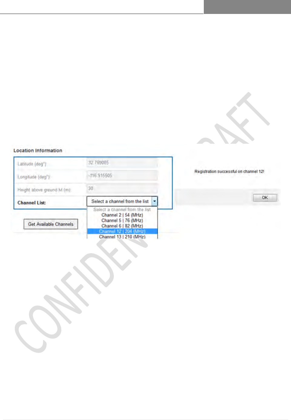
3.8 Selecting an Available Channel
Upon a successful registration: 3.8.1
3.8.1.1 All the fields are locked and prevented from being modified;
3.8.1.2 TV channel list is available with the geographically available channels. To assign
the device to an available channel simply select the desired channel from the
drop-down list.
3.8.1.3 While the RaptorX is registered the list of available channels can be refreshed at
any point by clicking the ‘Get Available Channels’ button.
3.8.1.4 After registering a valid TV channel the radio is now ready for operation. To
begin, complete the ‘Radio Information’ form and ensure the ‘Enable Radio’
option is set to “Yes”. Click on ‘Apply Changes’, the RaptorX device will
complete the registration and start radio operation on the appropriate TV
channel. In the sample above we have selected TV Channel 12, center frequency
204 MHz
3.8.1.5 If any issues occur go back to the first step and follow the instructions carefully.

RAPTORX USER MANUAL Version 1.07
January 22, 2015
19 | P a g e
3.8.1.6 To unassign a channel but keep the RaptorX registered simply select the first
option in the drop-down list that reads ‘Select a channel from the list’ (colored
grey).
RAPTORX USER MANUAL Version 1.07
January 22, 2015
20 | P a g e
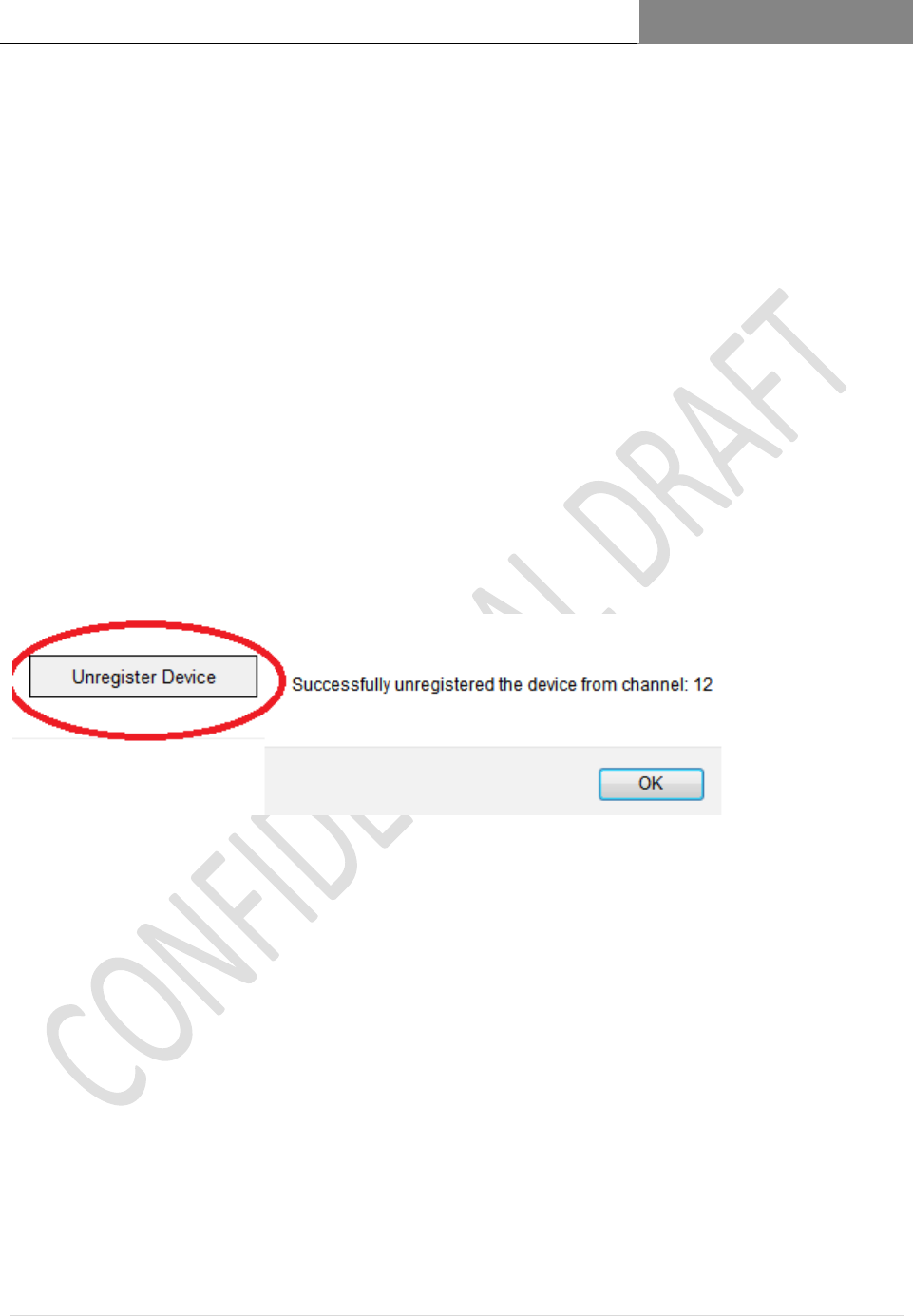
Unregistering the RaptorX 3.8.2
3.8.2.1 When the device is in registered mode the ‘Unregister Device’ button becomes
enabled
3.8.2.2 If the device needs to go into the unregistered mode the user must press the
‘Unre20gister’ button
3.8.2.3 Unregistering the RaptorX will send it back to unregistered mode after
successfully dropping the registered channel followed by completely
unregistering the device.
*To change any fields the device must be in unregistered mode.
*Unregistering the device will allow changes to all form information
RAPTORX USER MANUAL Version 1.07
January 22, 2015
21 | P a g e

RAPTORX USER MANUAL Version 1.07
January 22, 2015
22 | P a g e
Appendix 1 Communications Protocol between the TVBD and the
Certified FCC Database
1. What communication protocol is used between the database and the TVBD?
The TVBD connects to the iConectiv database using HTTP over SSL/TLS. The protocol used over
this transport layer is specified by the IETF Protocol to Access White Space (PAWS) Draft-12
specification.
2. How are communications initiated?
The TVBD initiates communication with the iConectiv database by sending first sending an
INIT_REQ message containing a Device Descriptor. The Device Descriptor element contains the device
serial number, manufacturer ID, and model ID, which in the US is FCC ID.
3. How does the TVBD validate messages from the database?
The identity of the iConectiv database is validated through verification of the iConectiv SSL
certificate through standard third-party certificate authority mechanisms, ensuring the communications
are secure and authentic between the TVBD and the database.
At the application layer both the TVBD and database only handle messages that conform to the
PAWS protocol specification. One additional message validation feature included in PAWS is the ability
for the TVBD to correlate a response with a specific request by comparing the message’s ID field with the
ID field of the request that was sent.
4. How does the device handle failure to communicate or authenticate the database?
If the TVBD has never communicated with or authenticated the database, then it will not begin
operation. If once operating, experiences a communication or authentication failure, then it will cease
operation at 11:59 PM on the following day.
5. How does the database validate messages from a TVBD?
The database validates messages from the TVBD by checking the serial number and FCC ID received
in the Device Descriptor data element in every message versus a table of valid client devices that is
populated when the device is manufactured. The list of valid serial numbers is communicated from device
manufacturer to iConectiv via “out-of-band means,” such as email or telephone.
6. What encryption method is used?
SSL/TLS standard encryption is used to encrypt packets send between TVBD and database.

RAPTORX USER MANUAL Version 1.07
January 22, 2015
23 | P a g e
7. How does the database ensure secure registration of protected devices?
In this document, we interpret “protected devices” to mean entities authorized by the rules for
protection from TVBDs, e.g., Temporary BAS, MVPD, Licensed and Unlicensed Microphones.
iConectiv provides a public interface that is available to entities authorized for protection under CFR
Title 47 Part 15 Subpart H. The iConectiv registration system requires entities seeking protection to
register for an account on the iConectiv site before they can create protected contours. Once a user
creates an account, they can create new and view previously created registrations via the iConectiv
registration site.
iConectiv maintains two parallel registration sites. The first, production registration site, is available
to entities seeking protection from operational TVBDs. The second, test and integration site is available
to those device manufacturers looking to integrate with the iConectiv database and to FCC and test
laboratories looking to test functionality of a TVBD operating in conjunction with the iConectiv database.
The test and integration site is provided so as to not corrupt data in the live production site with records
used for testing only.
The two registration sites can be accessed via these addresses:
1. Live production registration site: https://spectrum.iconectiv.com/main/reg/
2. Test and integration registration site:; https://spectrum.iconectiv.com/dev/reg/
Testers should note that while a device is being tested for certification, it will be connecting to the
iConectiv test and integration server. To test the TVBD for operation in conjunction with registered
protected entities, the tester must register for protection on the test and integration server (#2) listed
above.
RAPTORX USER MANUAL Version 1.07
January 22, 2015
24 | P a g e
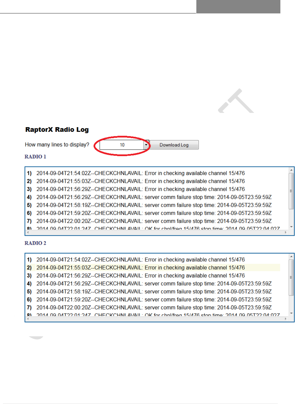
Appendix 2 Logging
When the RaptorX successfully executes certain operations (registering channel, checking channel
availability, etc.) the output of the execution is sent to a log file. This log file can be displayed on the
“Radio Logging” page.
The output of the logs is the most recent N lines of the log file where N is the number in the drop-
down selector outlined in red below. If the entire log is needed there is a “Download Log” button which
will securely download the log file for the radio(s).
RAPTORX USER MANUAL Version 1.07
January 22, 2015
25 | P a g e
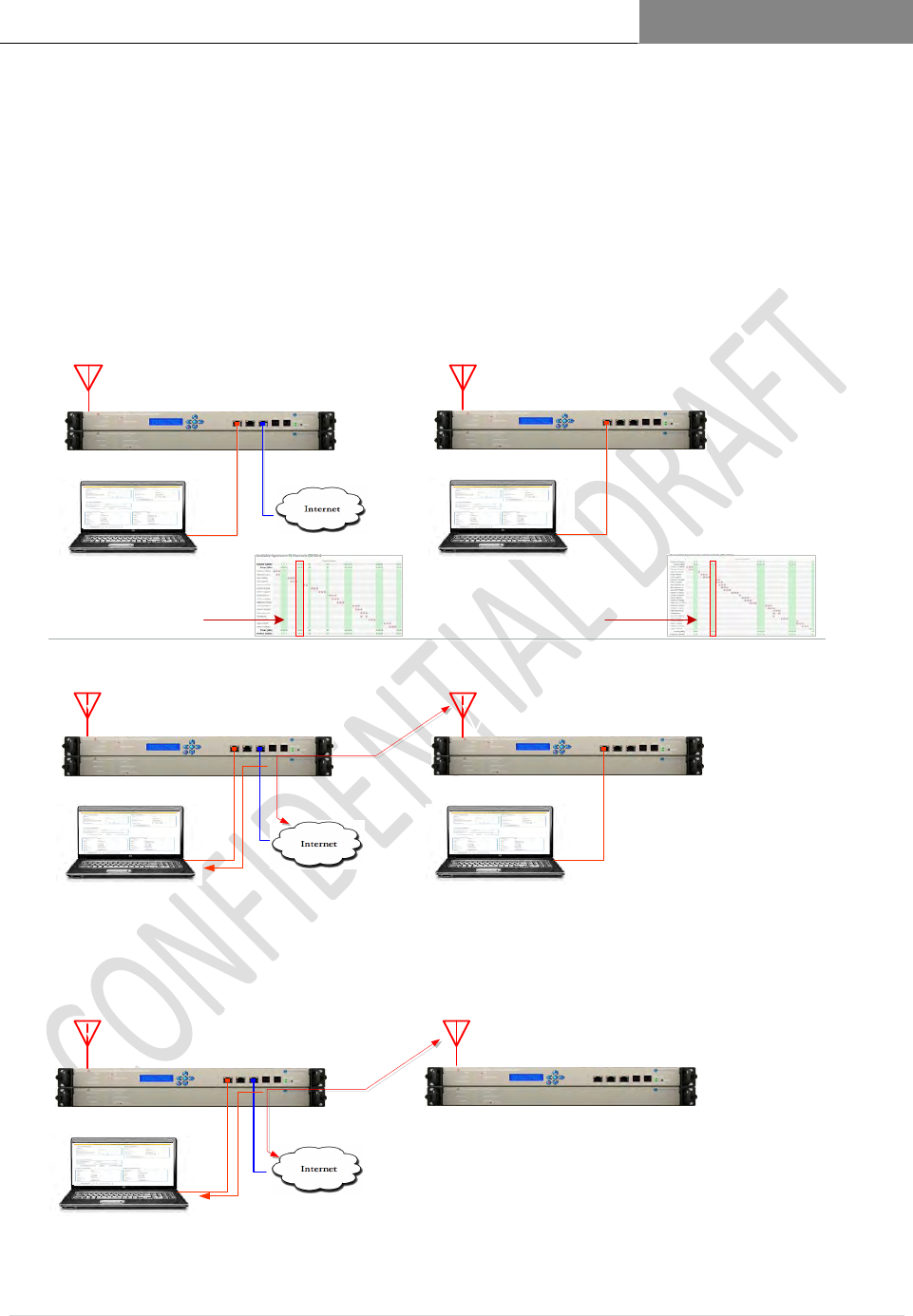
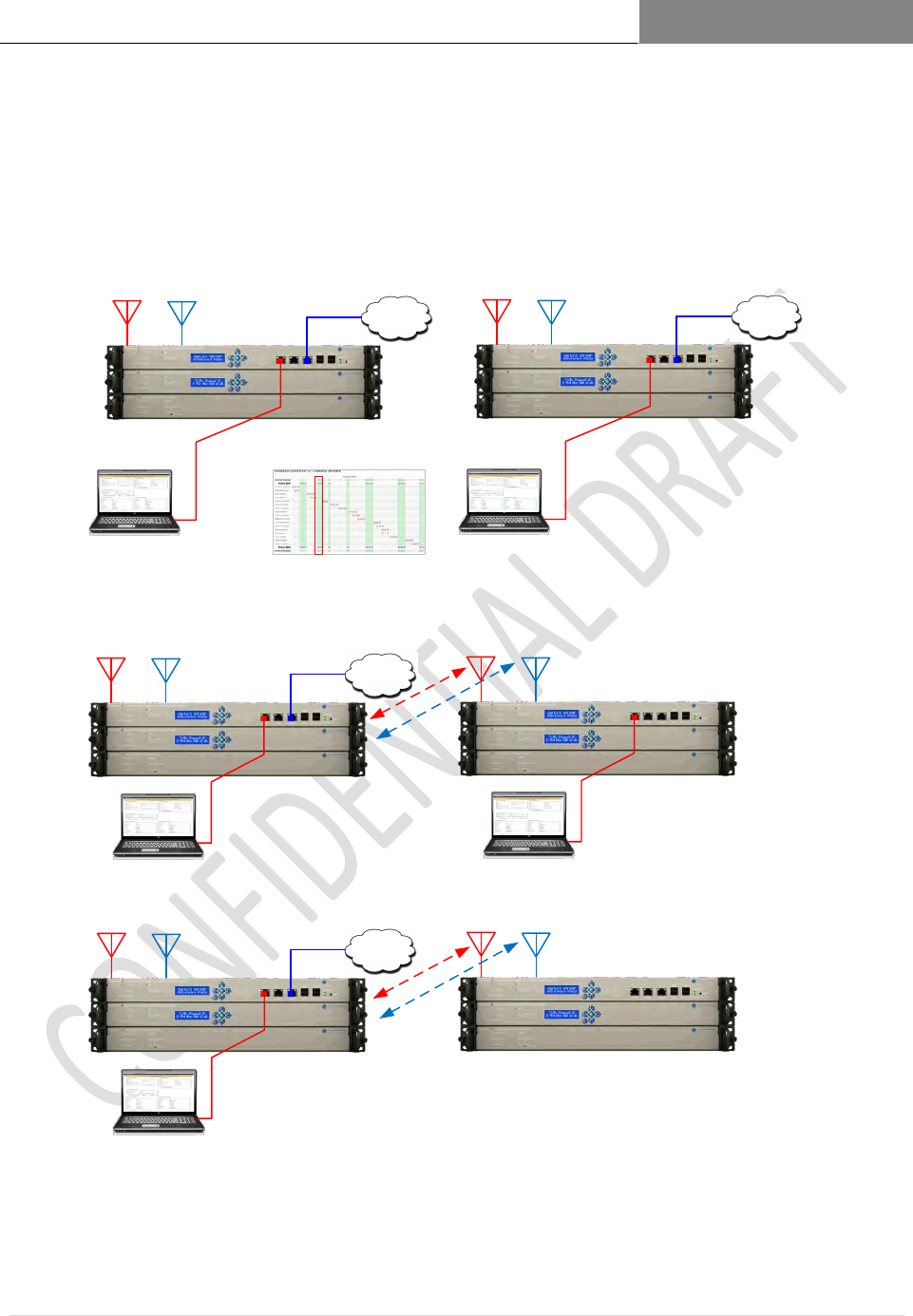
Figure 1.8 Professional Installation Single Channel Point-to-Point Link
The figures below illustrate the process of registration and database maintenance between
Base and Remote Units:
Access Registration Page via Web
Browser @ 192 . 168 .1.1
Access Registration Page via Web
Browser @ 192 . 168 .1.1
Access Registration Page via Web
Browser @ 192 . 168 .1.1
Access Registration Page via Web
Browser @ 192 . 168 .1.1
Access Registration Page via Web
Browser @ 192 . 168 .1.1
RAPTORX BASE UNIT RAPTORX REMOTE UNIT
Using an FCC certified
White Space
database, determine
channel availability at
each site.
VPN Tunnel
between
RAPTORX BASE UNIT RAPTORX REMOTE UNIT
RAPTORX BASE UNIT RAPTORX REMOTE UNIT
REGISTRATION
CONFIRMATION
Site: Peters, CA
Latitude: 37.975615
Longitude: -121.043531
Site: Milton, CA
Latitude: 38.0033398
Longitude: -121.851956
Step 1: Pre-deployment
●Using a web-based FCC White Space database provider ascertain available channels at deployment sites.
●Confirm engineering requirements
Step 2: Base Unit Deployment
●Deploy each Base Unit.
●Re-register RaptorX using updated GPS coordinates, if required.
For Base Unit, channel 12 is
available and selected.
In the Remote Unit, channel 12 is
available and selected.
Step 3: Operational Status
●In operation the Base and Remote Units operate independently. Accessing the Database asynchronously, the
Remote securely tunnels through the Base Unit to access the internet. When required, installer can access the
Remote Unit through the Base Unit PC across the internet.
RAPTORX USER MANUAL Version 1.07
January 22, 2015
26 | P a g e
RAPTORX BASE UNIT RAPTORX REMOTE UNIT
VPN Tunnel
between
RAPTORX BASE UNIT RAPTORX REMOTE UNIT
RAPTORX BASE UNIT RAPTORX REMOTE UNIT
Site: Peters, CA
Latitude: 37.975615
Longitude: -121.043531
Site: Milton, CA
Latitude: 38.0033398
Longitude: -121.851956
Channel 1 Channel 2 Channel 1 Channel 2
Channel 1 Channel 2 Channel 1 Channel 2
Channel 1 Channel 2 Channel 1 Channel 2
RaptorX Channel 1: TV Channel 12: Fc=207 MHz
RaptorX Channel 2: TV Channel 13: Fc=213 MHz
Database
FCC
Database
Database
FCC
Database
Database
FCC
Database
Database
FCC
Database
VPN Tunnel
between
Step 1: ● Confirm availability of two independent fixed channel stations using a certified web-based White Space
spectrum data base provider. In the example below, channels 12 and 13 are chosen. ●Independently register each
radio.
Step 2: Base Unit Deployment
● Deploy the Base Unit; reregister each radio and confirm channel
availability. Modify if required. ● Place each radio in low duty cycle
beacon mode.
Step 2A: Remote Unit Deployment
● Upon start-up each unit will automatically link to its respectively
assigned channel and establish a secure VPN to the Base Unit and to
the internet. ● Re-register each radio.
Step 3: Operation
Each radio will independently manage its
database reporting protocols according to
Subpart H requirements.
Registration PC Registration PC
Registration Confirmation
Figure 1.9 Professional Installation Dual Channel Point-to-Point Link
The figures below illustrate the process of registration and database maintenance between Base and Remote units.
RAPTORX USER MANUAL Version 1.07
January 22, 2015
27 | P a g e
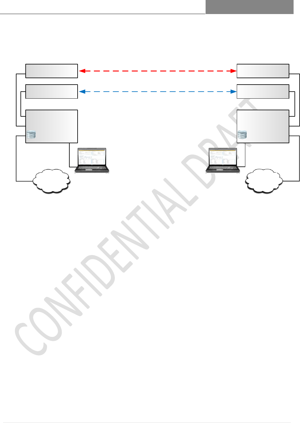
Figure 1.10 Registration Process for Dual Channel System
Primary
FCC
Database
Channel 1
VHF or UHF TV Band
Site 2Site 1
Station Network
Processor / Wireless
Controller
TVBD Radio 1
TVBD Radio 2
Site 1: Local Embedded
Spectrum Database
Station Network
Processor / Wireless
Controller
TVBD Radio 1
TVBD Radio 2
Secondary
FCC
Database
Site 2: Local Embedded
Spectrum Database
Channel 2
VHF or UHF TV Band
RaptorX offers the ability to establish a multi-channel station using a RaptorX Network Shelf
containing one VHF/UHF Tx/Rx unit and adding an additional channel via a Channel Expansion
Shelf. In this configuration, the Station Network Processor provides network control and
registration management for each station.
The Registration page provides the capability to register up to two (2) local stations. Once
registered, the Controller independently manages each radio. A spectrum fault in any radio does
not affect the remaining radio. The capability of utilizing a standby database link is shown
above. This capability will ensure un-interrupted operation in the event access to the primary IP
connection is lost.

RAPTORX USER MANUAL Version 1.07
January 22, 2015
28 | P a g e
Figure 1.11 Tx Power Control Mechanisms
Tx Power Control Mechanisms
Modem
Frequency
Conversion PA Driver
Final
Power
Amplifier
Tx
Harmonic
Filters
Forward /
Reverse
Pwr Meas
Diplexer
RxAGC
AntennaProcessor
Instantaneous Rx Signal Level
Average Packet-to-
Packet Rx Signal Level
Remote Site
Outbound
Power Levels
PA Power
Level Control
Automatic
Level Control
(ALC)
Fwd/Rev Pwr
Adjusted Power Level from
Registration Page
PA ALC Control
PA ALC Control
Tx Power Control is used to meet the following objectives:
Adjust and maintain output power to a level not to exceed 36 dBm EIRP under any
situation.
This objective is accomplished with the following process:
o On the Registration Page, entering the isotropic gain of the antenna (See Page 4).
The processor calculates the Tx attenuation factor required to maintain Tx
conductive power and EIRP within the required regulatory framework.
Maintaining the minimum adequate EIRP to maintain required service levels
Figure 4 above shows the Functional Block Diagram of a RaptorX Tx/Rx device and
associated power control lines.
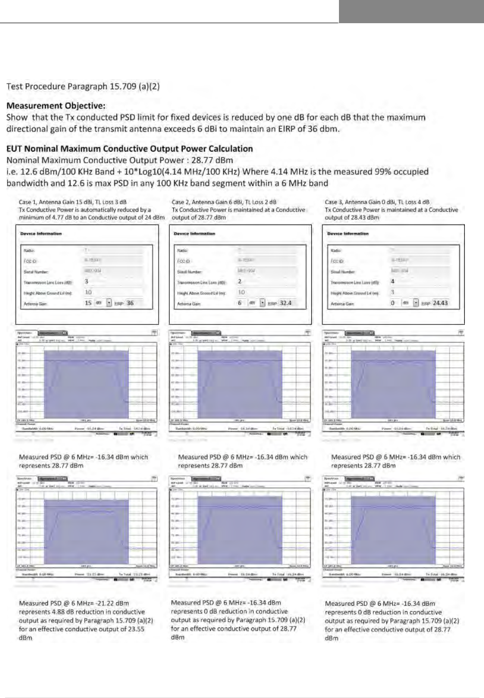
Figure 6 illustrates compliance with FCC Regulation 15.709 (a) (2) Sub Part H. The
minimum required for adequate Rx signal levels to maintain link connectivity. This
requirement is met by controlling outbound Tx Power based on Rx RSSI and required
SNR to maintain a given BER rate. For example, say a link using QPSK requires an
average SNR of 9 dB to maintain a BER of 10-6. If the measured SNR is 15 dB where
the excess is attributable to excess Rx energy, a power reduction protocol packet will be
sent to the far end instructing the transmitter to lower its power by 1dB increments to
arrive at a nominal Rx level.
RAPTORX USER MANUAL Version 1.07
January 22, 2015
29 | P a g e
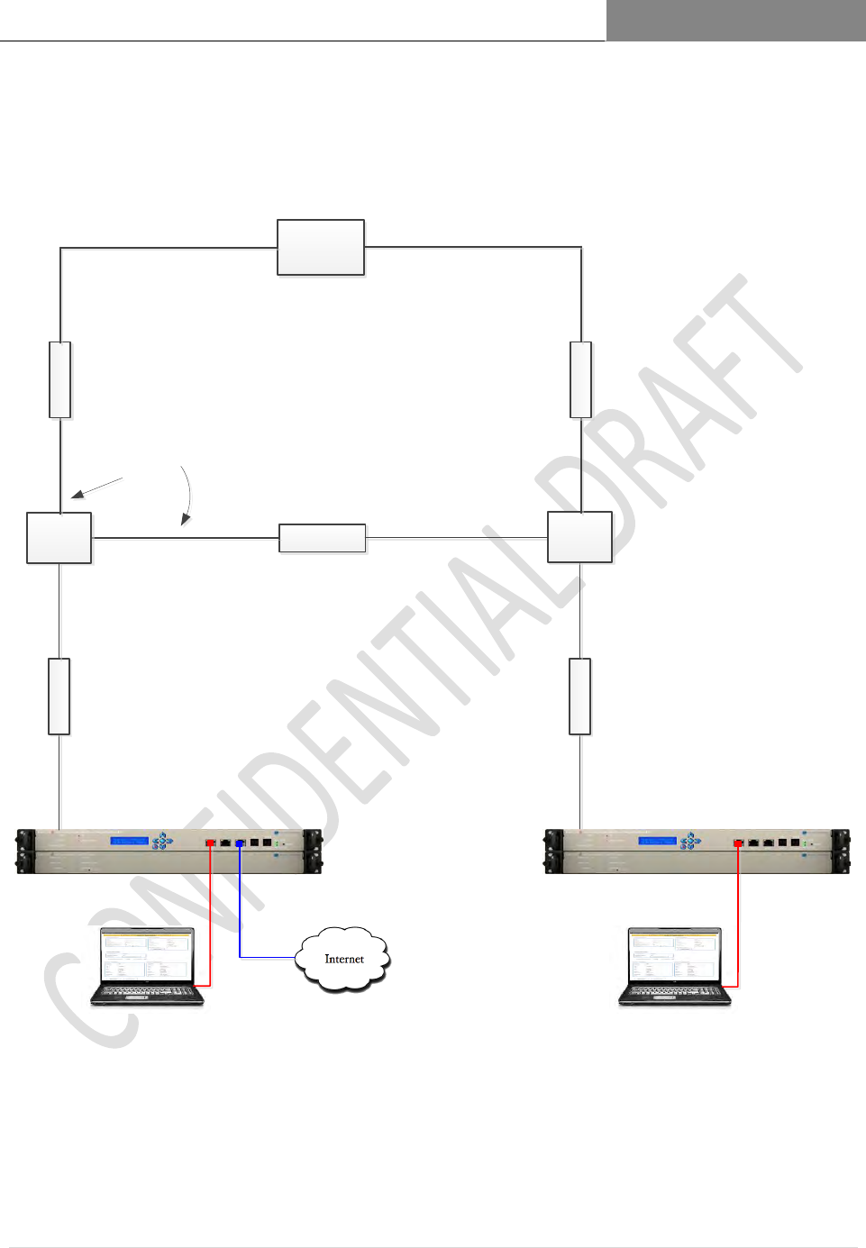
Figure 1.12 Test Set Up
2-Way
Splitter
Access Registration Page via Web
Browser @ 192 . 168 . 1 .1
Access Registration Page via Web
Browser @ 192 . 168 . 1 .1
2-Way
Splitter
Spectrum
Analyzer
Base PC Support PC
Data Signal Data Signal
RaptorX Base Unit RaptorX Remote Unit
RF Coaxial Connections
10 dB Attenuators 10 dB Attenuators
10 dB Attenuators
10 or 20 dB
Attenuators
10 or 20 dB
Attenuators
RAPTORX USER MANUAL Version 1.07
January 22, 2015
30 | P a g e
Figure 1.13 Test Procedure Paragraph 15.709 (a) (2)
RAPTORX USER MANUAL Version 1.07
January 22, 2015
31 | P a g e
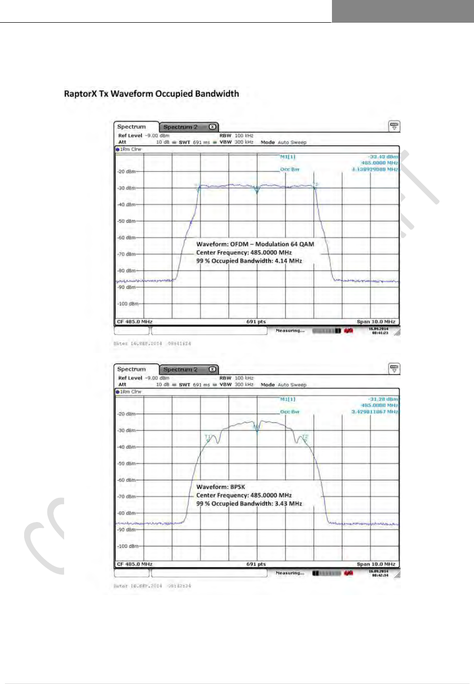
Figure 1.14 RaptorX Tx Waveform Occupied Bandwidth

RAPTORX USER MANUAL Version 1.07
January 22, 2015
32 | P a g e
4 RaptorX Network Design Process
This section describes the process and tools required to design White Space Station networks in several
steps. Intermediate steps common to all professional radio system deployment will be left to the
professional designer and installer.
4.1 Tools Needed:
Access to internet
Intended site parameters, i.e. possible available antenna location heights (establishing channel
availability and network band plan)
Spectrum Analyzer
PC with web browser
4.2 Step 1:
Determine as accurately as possible the latitude and longitude of each probable antenna site. Use
these coordinates on the Google Spectrum Data Base
https://www.google.com/get/spectrumdatabase/index.html to determine available White space
channels at the site of each planned White Space antenna.
Enter latitude and longitude, along with device type. Fixed for RaptorX and maximum antenna
height, 30 meters (98.4 feet). Click search for available channels.
You will be provided with all available channels for that site.
Site
Latitude
Longitude
# of Available Channels
(excluding Channels 2-
6)
Available Hi Band
VHF
Channels
Available UHF
Channels
Greenleaf, WI
44.31356
-88.09611
20
7-9, 13
14-19,32-35,44-47,51
McKenzie County,
ND
47.77910
-103.41576
34
13
16-35,39-51
Reno, NV
39.53087
-119.81390
4
10,11
39,41
Kuparuk Oil Field,
AL
70.05186
-150.06762
42
7-13
14-35,39-51
Permian Basin, TX
31.93900
-102.2276
12
11-13
14,16,28,34,44,45,47,48
Table 2: Example of Available Channels per Google White Space Database
https://www.google.com/get/spectrumdatabase/index.html

RAPTORX USER MANUAL Version 1.07
January 22, 2015
33 | P a g e
4.3 Step 2:
Selecting Available Channels to Use (using an RF Planning Tool)
Several general guidelines should be used here:
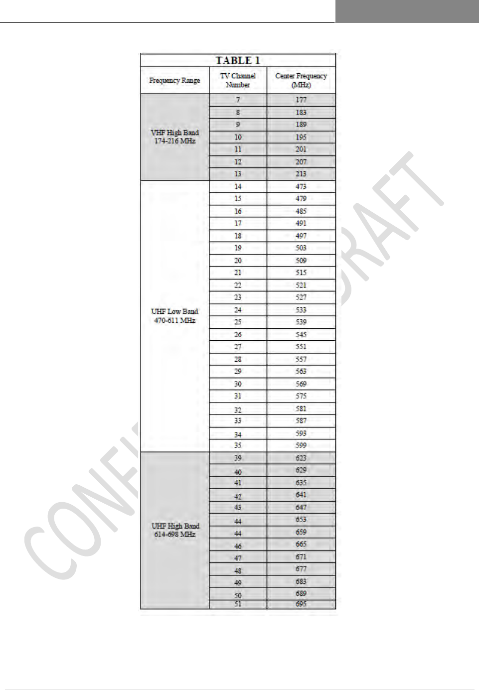
Choose a channel/frequency (see frequency chart) that will provide you with sufficient
signal and fade margin to provide 99% worst case reliability expectation over the path
and range in which you will operate.
RaptorX uses an adaptive modulation process that works to maximize data throughput for
a range of Rx signal levels vs local noise levels.
4.4 RaptorX RF System Design Parameters
Tx Subsystem: 4.4.1
OFDM/QAM Max RMS average Tx conductive output power: 28.8 dBm (.76 Watt)
(99% occupied bandwidth)
BPSK/QPSK Max RMS average Tx conductive output: 28 dBm (.631 Watts) (99%
occupied bandwidth)
Transmission line loss power compensation: 2.0 dB max, automatically calculated at time
of FCC registration.
99% signal bandwidth: 4.2 MHz
Only FCC–approved antennas must be used with the RaptorX. Please contact
RaptorX@metricsystems.com if you intend to use an antenna other than our standard
models.
Rx Subsystem: 4.4.2
Rx Sensitivity vs Nominal Data Throughput vs Modulation Mode
Sensitivity
Data Throughput
Modulation Rate
-85 dBm
1.5 mbps
BPSK
-80 dBm
2.0 mbps
QPSK
-77 dBm
2.5 mbps
QAM16
-70 dBm
4.0 mbps
QAM64
Table 3: Rx Sensitivity vs Modulation Rate (local noise floor less than, or equal to, -89 dBm)

RAPTORX USER MANUAL Version 1.07
January 22, 2015
34 | P a g e
Channel Bonding and Aggregation - RaptorX supports bonding of multiple 4.4.3
White Space channels to increase data throughput and provide link
redundancy in the event a link is lost or degraded.

RAPTORX USER MANUAL Version 1.07
January 22, 2015
35 | P a g e
4.5 Antennas:
The RaptorX is certified to operate with the following VHF and UHF antennas to fit various
deployment scenarios. When you register the RaptorX you will be required to include on the
Registration Application the chosen antenna, including the height and latitude and longitude
center. This information will be used to automatically configure the RaptorX to provide peak
link performance. (See appendix for antenna details.)
VHF Directional Antenna (9dBi)
UHF Log Periodic Antenna (10.15 dBi)
UHF High Gain Semi-Parabolic Antenna (16 dBi)
Transmission System (Transmission Line + EMP Protectors) 4.5.1
We recommend that a Low-Loss LMR-600 coaxial cable with waterproof connectors be
used.

RAPTORX USER MANUAL Version 1.07
January 22, 2015
36 | P a g e
4.6 Basic Examples:
Point-to-Point: VHF link
Point-to-Point: UHF Link
VHF POINT-TO-POINT LINK BETWEEN ONEIDA AND GREENLEAF SYSTEM
DESCRIPTION
Site 1/Oneida: Lat: 44.31366 Long:
Site 2/Greenleaf: Lat: Long:
Antenna Type: Kathrein DRV VHF-TV Panel Antennas, 174-230 MHz
o Gain dBd = 7, Gain dBi = 9.15
Link Range: 13.5 Miles/21.76 Km
Minimum System Margin Required: 6 dB for 32 QAM
Planned throughput: 2DS1s (2 x 1.544 mbps): 3.088 mbps
See Figure 2 for Path Profile, Rx Signal Level and Margin and available VHF and
UHF Channels for each site.
UHF POINT-TO-POINT LINK BETWEEN SCRAYS HILL AND FLINTVILLE SYSTEM
DESCRIPTION
Site 1/Scrays Hill: Lat: Long:
Site 2/Flintville: Lat:` Long:
Antenna Type: Kathrein High Gain 15 dBi Parabolic Directional Antennas
Range: 17.3 Miles (27.9 km)
Minimum System Margin: 6.5 dB
Planned Throughput: 2 DS1s (2 x 1.544 mbps): 3.088 mbps
RAPTORX USER MANUAL Version 1.07
January 22, 2015
37 | P a g e
Figure 1.15 Common Available Channels VHF Hi-Band: 2 Channels
(8,9)
Antenna Height: 95 feet
Range: 13.5 miles (21.76 km)
Tx Ant Gain: 6 dBi; Antenna Gain: 9.15 dBi
Rx Ant Gain: 9.15dBi
UHF White Space Point-to-Point Link
Channels: 13- 51; Range: 17.3 miles (27.9 km)
EIRP: 36 dBm; Rx Ant Gain: 15 dBi
Ant Height: 98”
Scrays Hill
Flintville
Available White Space Channels (shown in green) at Flintville Site
Available White Space Channels (shown in green) at Scrays Site

RAPTORX USER MANUAL Version 1.07
January 22, 2015
38 | P a g e
Oneida
Greenleaf
Available White Space Channels (shown in green) at Oneida Site
Available White Space Channels (shown in green) at Greenleaf Site
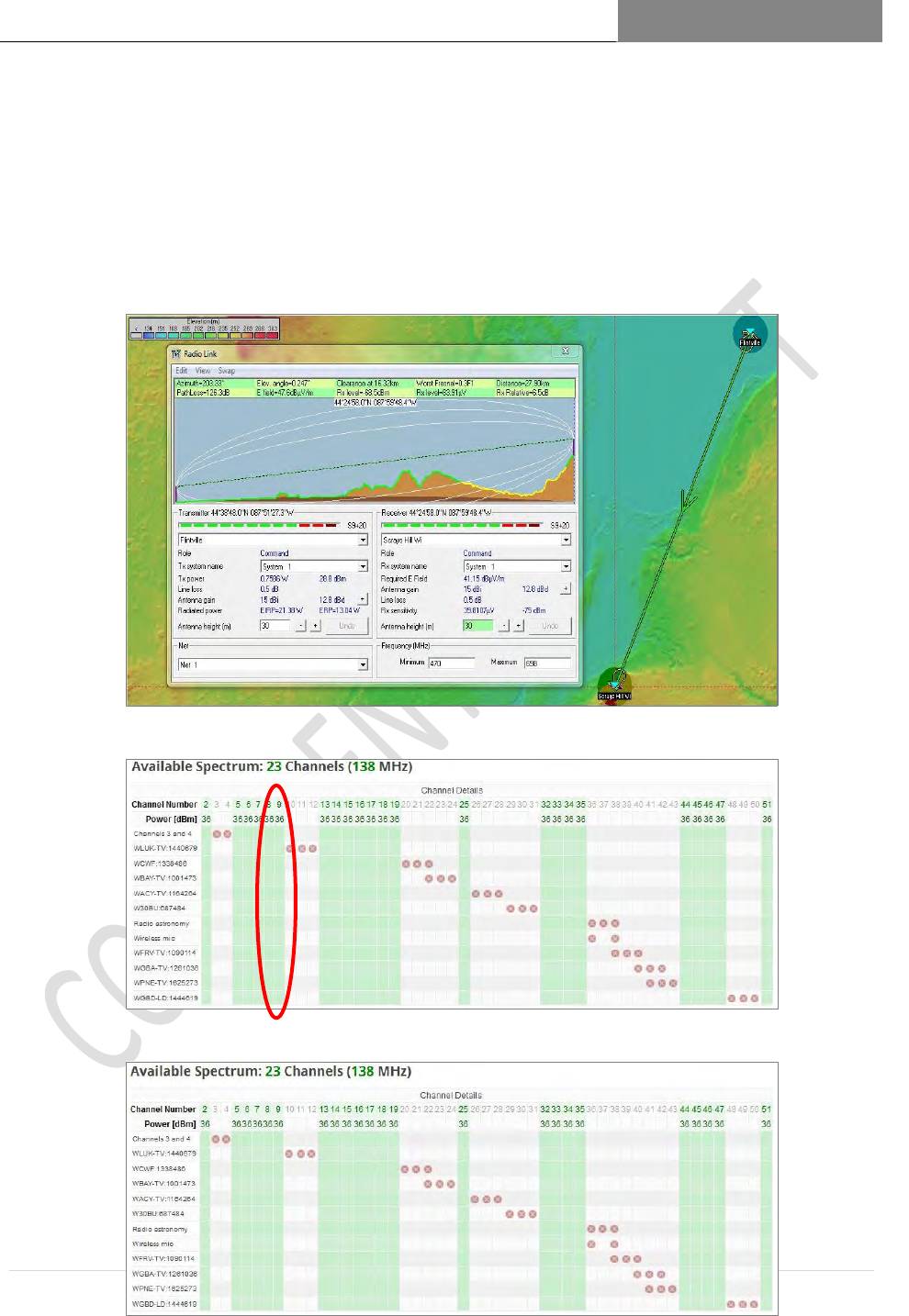
Figure 1.16 UHF White Space Point-to-Point Link
Common UHF Channels Available: 17 (Channels 13-19,25 ,32,35,44-47,51)
Antenna Height: 98”
Range: 17.3 miles (27.9 km)
EIRP: 36 dBm, Rx Antenna Gain: 15 dBi

RAPTORX USER MANUAL Version 1.07
January 22, 2015
39 | P a g e
See Page 4 for Path Profile Rx Signal Level and Expected Margin and available3 UHF Channels for each
antenna site. In each case for these sites the system designer has a number of deployment channels to
choose from.
5 Summary
The major new elements in designing with White Space spectrum are:
Channel Selection via an on-line database, choosing from an available channel list
an appropriate channel(s) in which to operate.
Evaluating link performance using an RF System Planning application, e.g.
Pathlink 5 or Radiomobile.
5.1 Provisioning RaptorX Radios:
FCC-certified RaptorX radios, as shipped, are not pre-configured to operate at any channel. The
radios per FCC, Part 15 Subpart H Rules must be successfully registered via the internet with a
certified FCC Database Provider. Metric Systems Corporation has contracted with iconectiv.com
(http://iconectiv.com/spectrum-mgmt/white-spaces/index.html )for this service.
RAPTORX USER MANUAL Version 1.07
January 22, 2015
40 | P a g e
Equipment Configuration:
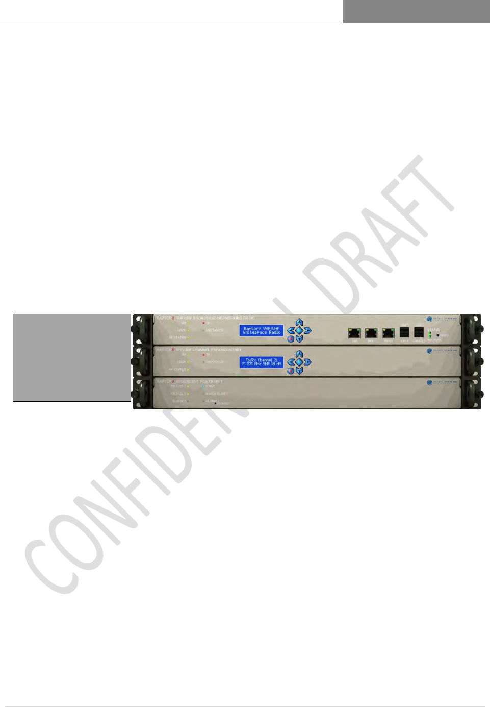
A basic RaptorX node consists of three (3) components.
a. RaptorX Network Controller Shelf, also called Primary Shelf. The Primary Shelf acts as the
core controller of the local RaptorX node. It consists of three elements,
a powerful Linux-based power PC processor;
an adaptive waveform modem that automatically selects the best modulation to
utilize to maximize performance over the RF path
and a very linear frequency agile transmitter receiver assembly.
b. Channel Expansion Shelf or Secondary Shelf which provides an additional independent
White Space channel. This shelf is controlled through RaptorX’s Primary Shelf.
c. The Redundant Power Unit Shelf maintains system operation in the event an individual
system power fails, whether provisioned as a single or dual channel configuration.
Primary RaptorX Shelf
Secondary Shelf
Redundant Power Unit
RAPTORX USER MANUAL Version 1.07
January 22, 2015
41 | P a g e
RAPTORX USER MANUAL Version 1.07
January 22, 2015
42 | P a g e
RAPTORX USER MANUAL Version 1.07
January 22, 2015
43 | P a g e
RAPTORX USER MANUAL Version 1.07
January 22, 2015
44 | P a g e
RAPTORX USER MANUAL Version 1.07
January 22, 2015
45 | P a g e

RAPTORX USER MANUAL Version 1.07
January 22, 2015
46 | P a g e
6 Technical Reference
6.1 RMA Procedure
RETURN MATERIAL AUTHORIZATION PROCEDURE
1. To request a return material authorization (RMA) number, contact Metric Systems
Corporation at (760) 560-0348 or email us at info@metricsystems.com. When calling, please be
prepared to provide the following information:
• Your name, company, telephone and fax numbers and e-mail address;
• Part and/or model number (if applicable) of the system components to be returned;
• Reason for return and repair disposition authority.
A purchase order number will be requested at the time we issue an RMA number. Note: non-
warranty costs can be incurred through shipping damage, misuse or product misapplication. It is assumed
that the user has protected the returned component from EMI/EMP and environmental damage. The user
will be billed for items found to be defective due to the above factors.
2. Once an RMA number has been issued, ship the product to be returned to the following address:
Metric Systems Corporation
3055 Enterprise Court
Vista, CA 92081
Attn: RMA Number _______
3. For out-of-warranty repairs, you are responsible for paying all freight expense, any applicable
import and/or export duties and taxes. You are responsible for delivering the returned product
safely and undamaged to MSC.
4. On receipt of the product returned under an RMA number, an e-mail will be sent to you
confirming receipt of product and quantities received.
5. All products returned under warranty will be repaired or replaced at the sole discretion of Metric
Systems Corporation with new or equivalent materials.
RAPTORX USER MANUAL Version 1.07
January 22, 2015
47 | P a g e
Customer Information email us at info@metricsystems.com
Bill To:
Ship To:
Company Name
Company Name
Street Address
Street Address
City, State, Zip Code
City, State, Zip Code
Contact
Contact
Phone
Phone
Fax
Fax
E-mail address
E-mail address
Purchase Order, Warranty and General Instructions
Your PO# for Repair
Authorized by (if no PO provided)
Method of Payment
Original PO number(s) under which the Unit(s)
were shipped
Service Contract if Any
Product to be repaired
Item
#
Qty
Model/Part No.
Serial Number
Symptom or Problem
1
2
3
4
Your Special Instructions
IMPORTANT NOTICE: By submitting the product described above to MSC for repair, Customer acknowledges and agrees that it shall pay the
amount charged by MSC for the repairs immediately upon receipt of written notice (or proforma invoice) from MSC setting forth the date of
completion of repairs and the total amount due. If the amount due remains unpaid ninety (90) days after delivery of such written notice to
Customer, MSC at its option, shall have the right to retain the product or dispose of such product. MSC may retain the proceeds of any sale of
product as payment for the costs associated with the repair and disposition of the product plus reasonable costs of storing the product
(“Costs”). By submitting the product to MSC, Customer further agrees that it waives any obligation of MSC to take any actions, other than
those actions set forth herein, prior to retaining or disposing of the product. Upon the written request of Customer, MSC will submit to the
Customer any amount obtained from the disposition of the product in excess of the Costs.