METRIC SYSTEMS 50911-U TVWS Fixed Wireless Networking Radio System User Manual RAPTORXR VERSION 1 10
METRIC SYSTEMS CORPORATION TVWS Fixed Wireless Networking Radio System RAPTORXR VERSION 1 10
RAPTORXR USER MANUAL REV. 1.6 10 October 2017 GENERAL USE

REV. 1.10
05/02/17

[RAPTORXR USER MANUAL VERSION 1.10]
May 2, 2017
2 | P a g e
FCC Regulatory Information
FCC ID: 2ABCU-507391P-U
This device complies with part 15 of the FCC Rules. Operation is subject to the following two conditions: (1)
This device may not cause harmful interference, and (2) this device must accept any interference received,
including interference that may cause undesired operation.
Any changes or modifications not expressly approved by the party responsible for compliance could void the
user’s authority to operate the equipment.
Part 15 TV Band Device Notice
This equipment has been tested and found to comply with the rules for TV bands devices, pursuant to part 15
of the FCC rules. These rules are designed to provide reasonable protection against harmful interference.
This equipment generates uses and can radiate radio frequency energy and, if not installed and used in
accordance with the instructions, may cause harmful interference to radio communications. If this equipment
does cause harmful interference to radio or television reception, which can be determined by turning the
equipment off and on, the user is encouraged to try to correct the interference by one or more of the following
measures:
(1) Reorient or relocate the receiving antenna.
(2) Increase the separation between the equipment and receiver.
(3) Connect the equipment into an outlet on a circuit different from that to which the receiver is connected.
(4) Consult the manufacturer, dealer or an experienced radio/TV technician for help.
Caution: Exposure to Radio Frequency Radiation.
To comply with FCC RF exposure compliance requirements, for fixed configurations, a separation distance
of at least 40 cm must be maintained between the antenna of this device and all persons.
This device must not be co-located or operating in conjunction with any other antenna or transmitter
LEGAL NOTICE
The information contained herein is the property of Metric Systems Corporation (“MSC”) and is supplied
without liability for errors or omissions. No part of this document may be reproduced, in any form,
except as authorized by contract or other written permission from the owner.
Any brand name and product names included in this manual are trademarks, registered trademarks, or
trade names of their respective holders.
The contents of this document are current as of the date of publication. MSC reserves the right to change
the contents without prior notice.
The publication of information in this document does not imply freedom from patent or other rights of
MSC or others.
2016 Metric Systems Corporation. All rights reserved. The MSC logo is a trademark of Metric Systems
Corporation. RaptorXR is a trademark of Metric Systems Corporation.
2ABCU-50911-U

[RAPTORXR USER MANUAL VERSION 1.10]
May 2, 2017
3 | P a g e
Open Source License Information
Per the terms of your Metric Systems Limited Hardware Warranty, Software License, and RMA
Procedures Agreement with Metric Systems Corporation., certain Third Party Software may
be provided with and as part of the MSC products provided to you, and any such Third Party Software
files provided are governed by the terms of their separate Third Party Licenses, which licenses give
you at least the license rights licensed to you in the MSC End User Agreement and may give you
additional license rights as to the Third Party Software, but only with respect to the particular Third
Party Software to which the Third Party License applies.
The MSC Products may include or be bundled with some or all of the following third party software.
Copies of the copyright notices and license agreements for any or all of these may be requested by
contacting MSC support at email: info@metricsystems.com.
Open Source Code
License Agreement
Website
Patents
The RaptorXR employs techniques and methods incorporated in Metric Systems Corporation’s U.S. and
Canadian patents listed below. The use of this technology provides the user with a robust and versatile
system to meet the stringent requirements of a dynamic frequency allocation broadband wireless system.
ITEM
S/N
TITLE
1
6,952,563US
Method and apparatus for adaptively setting frequency channels in a multi-
point wireless networking system
2
7,013,345US
Method and apparatus for wireless networking
3
7,089,014US
Wireless communication system control apparatus and method
4
2,417,931CA
Method and Apparatus for Adaptively Setting
5
2,444,643CA
Method and Apparatus for Wireless Networking
6
2,444,805CA
Wireless Communication System Control

[RAPTORXR USER MANUAL VERSION 1.10]
May 2, 2017
4 | P a g e
BLANK

[RAPTORXR USER MANUAL VERSION 1.10]
May 2, 2017
5 | P a g e
RaptorXR User Manual
Part Number 50739.1.P Series
TABLE OF CONTENTS
LEGAL NOTICE .............................................................................................................. 2
Open Source License Information ................................................................................... 3
Patents ............................................................................................................................ 3
Table of Contents ............................................................................................................ 5
List of Figures and Tables ............................................................................................... 5
Revision History .............................................................................................................. 9
Standard Hardware One (1) Year Warranty .................................................................. 10
Manual Overview ........................................................................................................................ 13 1.1
Documentation Conventions ....................................................................................................... 14 1.2
Abbreviations and Terminology ................................................................................................. 15
1.3
2 RaptorXR Overview .................................................................................................. 17
System Benefits .......................................................................................................................... 17 2.1
Operational Capabilities .............................................................................................................. 18 2.2
Operating and Technical Specifications...................................................................................... 18 2.3
Figure 1.1: Basic RaptorXR Point-to-Point Backhaul Configuration ..................................................... 19
The RaptorXR Hardware Suite ..................................................................................................... 24 2.4
3 GETTING STARTED .............................................................................................. 31
EXAMPLE .................................................................................................................................. 31 3.1
4 Accessing VHF/UHF TV Band Spectrum ................................................................ 34
To access the Registration page insert the IP address: 192.168.1.1 .......................................... 34 4.1
Insert required device and location information. Click Registration. ......................................... 34 4.2
Upon a successful registration a list of available White Space channels will be returned. ......... 34 4.3
Select the appropriate TV channel to complete registration and activate the Tx subsystem ..... 34 4.4

[RAPTORXR USER MANUAL VERSION 1.10]
May 2, 2017
6 | P a g e
The remaining sections will describe in detail the Registration process. The RaptorXR
4.5
Database Registration Engine will automatically validate and re-register the unit every 24 hours. ....... 34
5 RaptorXR Network Design Process .......................................................................... 35
The major new elements in designing with White Space spectrum are: .................................. 35
Operating Channel Selection via an on-line secure database ...................................................... 35 5.1
Need to evaluate and predict link performance using an RF System Planning application, ...... 35 5.2
RaptorXR certified radios, as shipped, are not pre-configured to operate at any channel .......... 35 5.3
Tools Needed: ............................................................................................................................. 35 5.4
Step 1:DETERMINE LAT/LONG ............................................................................................. 36 5.5
Step 2: Selecting Available Channels to Use (using an RF Planning Tool) ............................... 37
5.6
Step 3: Manually Setting Full Duplex Data Rate ........................................................................ 38 5.7
System Margin Examples ........................................................................................................... 40 5.8
Link Budget Calculation ............................................................................................................. 40 5.9
System Margin Table .................................................................................................................. 43 5.10
Antennas ..................................................................................................................................... 44 5.11
Transmission System (Transmission Line + EMP Protectors) ................................................... 44 5.12
6 RaptorXR Data Base Registration ............................................................................ 45
Configuration and Registration Instructions Prior to Deployment ............................................. 46 6.1
Procedure for Unregistering a RaptorXR and Relocating to Another Location ........................... 48 6.2
Instructions for Checking Available Channels using the Google Spectrum Database or the 6.3
Spectrum Bridge Database. ..................................................................................................................... 49
The RaptorXR TV Band Device (TVBD) has two status modes: “Unregistered” and 6.4
“Registered”. ........................................................................................................................................... 51
Unregistered mode: ..................................................................................................................... 51 6.5
Registered mode: ........................................................................................................................ 51 6.6
Radio Transmission: ................................................................................................................... 51 6.7
To change any information after registration .............................................................................. 52 6.8
Completing the RaptorXR Registration Form .............................................................................. 53
6.9
Registering the RaptorXR ............................................................................................................. 54 6.10
Upon a Successful Registration: ................................................................................................. 56 6.11
Unregistering the RaptorXR ......................................................................................................... 57 6.12
Appendix 1 Communications Protocol between the TVBD and the Certified FCC Database ... 59 6.13
Provisioning RaptorXR Radios: .................................................................................................. 64 6.14

[RAPTORXR USER MANUAL VERSION 1.10]
May 2, 2017
7 | P a g e
7 Customer Service ................................................................................................... 65
RMA PROCEDURE ................................................................................................................... 65 7.1
8 Technical Appendices ............................................................................................. 67
Appendix A: RaptorXR Recommended Antenna Specification Sheets ...................................... 67 8.1
Appendix B ................................................................................................................................. 70 8.2

[RAPTORXR USER MANUAL VERSION 1.10]
May 2, 2017
8 | P a g e
List of Figures and Tables
FIGURE 1.1 BASIC RAPTORXR POINT TO POINT BACKHAUL CONFIGURATIONL .................. 19
FIGURE 1.A 5 MHZ WAVEFORM………………………………………… ......... ………………………….22
FIGURE 1.2 SINGLE LINK SYSTEM (FRONT VIEW) .......................................................................... 24
FIGURE 1.3 SINGLE LINK SYSTEM (REAR VIEW) ............................................................................ 27
FIGURE 1.4 SINGLE LINK DIVERSITY SYSTEM (REAR VIEW) ...................................................... 27
FIGURE 1.5 RAPTORXR DUAL LINK SYSTEM (FRONT VIEW) ..................................................... 28
FIGURE 1.6 DUAL LINK CONFIGURATION ....................................................................................... 28
FIGURE 1.7 DUAL LINK SYSTEM (REAR VIEW) ............................................................................... 29
FIGURE 1.8 EXAMPLE: TOPOLOGICAL PROFILE CARBELLA/PINECREST ................................. 33
FIGURE 1.9 EXAMPLE: POINT-TO-POINT PROFILE PINECREST/CARBELLA ............................. 33
FIGURE 1.10 EXAMPLE: POINT-TO-POINT PROFILE CARBELLA/PINECREST ........................... 33
FIGURE 1.11 GOOGLE SPECTRUM DATABASE ................................................................................ 37
FIGURE 1.12 EXAMPLE: VHF SYSTEM GAIN AND MARGIN .......................................................... 41
FIGURE 1.13 EXAMPLE: UHF SYSTEM GAIN AND MARGIN .......................................................... 42
FIGURE 1.14 RAPTORXR SET UP CONFIGURATION FOR REGISTRATION ................................. 50
FIGURE 1.15 REGISTRATION FORM ................................................................................................... 53
FIGURE 1.16 REGISTERING THE RAPTORXR .................................................................................... 54
FIGURE 1.17:RECOMMENDED DEPOT CONFIGURATION FOR SYSTEM TESTING ................... 61
FIGURE 1.18 EXAMPLE OF AVAILABLE CHANNELS PER GOOGLE WHITE SPACE DATABASE ........ 62
FIGURE 1.19 EXAMPLE OF AVAILABLE CHANNELS PER GOOGLE WHITE SPACE DATABASE ........ 63
FIGURE 2 RMA FORM..……………………………………………………………………………..….66
TABLE 1: EXAMPLE OF AVAILABLE CHANNELS PER GOOGLE .................................................. 36
TABLE 2: SINGLE CHANNEL USEFUL DATA RATES ....................................................................... 38
TABLE 3: CARRIER NOISE VS USEFUL DATA RATES ..................................................................... 39
TABLE 4: SYSTEM MARGIN TABLE .................................................................................................... 43
TABLE 5:FREQUENCY RANGE/ VHF TV CHANNELS ...................................................................... 58
TABLE 6:FREQUENCY RANGE/ UHF TV CHANNELS ...................................................................... 58

[RAPTORXR USER MANUAL VERSION 1.10]
May 2, 2017
9 | P a g e
Revision History
DATE OF
REVISION
REVISION
LETTER
DESCRIPTION OF
CHANGES
PAGES
CHANGED
09/30/14
Rev.1.06.2
BETA MANUAL RELEASE
03/3/15
Rev.1.07A
NEW MANUAL UPDATE
ALL
04/30/15
Rev. 1.07B
UPDATE
ALL
07/01/15
Rev. 1.08
UPDATE
ALL
10/5/16
Rev. 1.09
UPDATE ILLUSTRATIONS
etc
ALL
04/28/17
Rev.1.10 FCC
UPDATE
ALL

[RAPTORXR USER MANUAL VERSION 1.10]
May 2, 2017
10 | P a g e
Metric Systems Corporation (MSC)
Standard Hardware One (1) Year Warranty
LIMITED WARRANTY
1. WHAT THIS WARRANTY COVERS AND FOR HOW LONG:
MSC warrants the communications product, including original equipment ("Product"), against material defects in
material and workmanship for a period of one year from the date of sale.
MSC will, at its option, and at no charge, either repair the Product (with new or reconditioned parts); replace it with
the same or equivalent Product (using new or reconditioned Product). Repaired or replaced Product is warranted for
the balance of the original applicable warranty period. All replaced parts of the Product shall become the property
of MSC.
This warranty is extended by MSC to the original end user, and is not assignable or transferable to any other party.
This is the complete warranty for the Product manufactured by MSC. MSC assumes no obligations or liability for
additions or modifications to this warranty unless made in writing and signed by an officer of MSC. Unless made in
a separate written agreement between MSC and the original end user purchaser, MSC does not warrant the
installation, maintenance or on-going service of the Product.
MSC cannot be responsible in any way for any ancillary equipment not furnished by MSC which is attached to or
used in connection with the Product, or for operation of the Product with any ancillary equipment and all such
equipment is expressly excluded from this warranty. Because each system which may use the Product is unique,
MSC disclaims liability for range, coverage, or operation of the system as a whole under this warranty.
2. GENERAL PROVISIONS:
This warranty sets forth the full extent of MSC's responsibilities regarding the Product. Repair or replacement at
MSC's option, is the exclusive remedy. THIS WARRANTY IS GIVEN IN LIEU OF ALL OTHER EXPRESS
WARRANTIES. MSC DISCLAIMS ALL OTHER WARRANTIES OR CONDITIONS, EXPRESS OR IMPLIED,
INCLUDING THE IMPLIED WARRANTIES OR CONDITIONS OF MERCHANTABILITY AND FITNESS
FOR A PARTICULAR PURPOSE. IN NO EVENT SHALL MSC BE LIABLE FOR DAMAGES IN EXCESS OF
THE PURCHASE PRICE OF THE PRODUCT, FOR ANY LOSS OF USE, LOSS OF TIME, INCONVENIENCE,
COMMERCIAL LOSS, LOST PROFITS OR SAVINGS OR OTHER INCIDENTAL, SPECIAL, INDIRECT OR
CONSEQUENTIAL DAMAGES ARISING OUT OF THE USE OR INABILITY TO USE SUCH PRODUCT, TO
THE FULL EXTENT SUCH MAY BE DISCLAIMED BY LAW.
3. HOW TO GET WARRANTY SERVICE:
Within the warranty period purchaser must notify MSC at info@metricsystems.com or 760-560-0348 to request an
RMA. Please specify the exact nature of the problem.
4. WHAT THIS WARRANTY DOES NOT COVER:

[RAPTORXR USER MANUAL VERSION 1.10]
May 2, 2017
11 | P a g e
A) Defects or damage resulting from use of the Product in other than its normal and customary manner.
B) Defects or damage from Acts of War, misuse, accident, water, neglect, lightning or EMP damage, or any other
natural causes.
C) Defects or damage from improper configuration, testing, operation, maintenance, installation, alteration,
modification, or adjustment.
D) Breakage or damage to RF or IT components such as radios, transceivers, duplexers, transmission lines, routers,
hubs, switches, etc., unless caused directly by defects in material workmanship.
E) A Product subjected to unauthorized Product modifications, dis-assemblies or repairs (including, without
limitation, the addition to the Product of non-MSC supplied equipment) which adversely affect performance of
the Product or interfere with MSC's normal warranty inspection and testing of the Product to verify any
warranty claim.
F) Product which has had the serial number removed or made illegible.
G) Freight costs to and from the repair depot.
H) Illegal or unauthorized alteration of the software/firmware in the Product which prevents it from functioning in
accordance with MSC's published specifications or with the safety regulations or FCC type acceptance labeling
in effect for the Product at the time the Product was initially distributed from MSC.
I) Scratches or other cosmetic damage to Product surfaces that does not affect the operation of the Product.
J) That the software in the Product will meet the purchaser's requirements or that the operation of the software will
be uninterrupted or error-free.
K) Normal and customary wear and tear.
5. GOVERNING LAW
In the case of a Product sold in the United States, this Warranty is governed by the laws of the State of California.
6. PATENT AND SOFTWARE PROVISIONS:
MSC will defend, at its own expense, any suit brought against the end user purchaser to the extent that it is based on
a claim that the Product or its parts infringe a United States patent, and MSC will pay those costs and damages
finally awarded against the end user purchaser in any such suit which are attributable to any such claim, but such
defense and payments are conditioned on the following:
A) that MSC will be notified promptly in writing by such purchaser of any notice of such claim;
B) that MSC will have sole control of the defense of such suit and all negotiations for its settlement or compromise;
and
C) should the Product or its parts become, or in MSC's opinion be likely to become, the subject of a claim of
infringement of a United States patent, that such purchaser will permit MSC, at its option and expense, either to
procure for such purchaser the right to continue using the Product or its parts or to replace or modify the same so
that it becomes non-infringing or to grant such purchaser a credit for the Product or its parts as depreciated and
accept its return. The depreciation will be an equal amount per year over the lifetime of the Product or its parts
as established by MSC.

[RAPTORXR USER MANUAL VERSION 1.10]
May 2, 2017
12 | P a g e
MSC will have no liability with respect to any claim of patent infringement which is based upon the combination of
the Product or its parts furnished hereunder with software, apparatus or devices not furnished by MSC, nor will
MSC have any liability for the use of ancillary equipment or software not furnished by MSC which is attached to or
used in connection with the Product. The foregoing states the entire liability of MSC with respect to infringement of
patents by the Product or any its parts thereof.
Laws in the United States and other countries preserve for MSC certain exclusive rights for copyrighted MSC
software such as the exclusive rights to reproduce in copies and distribute copies of such MSC software. MSC
software may be used in only the Product in which the software was originally embodied and such software in such
Product may not be replaced, copied, distributed, modified in any way, or used to produce any derivative thereof.
No other use including, without limitation, alteration, modification, reproduction, distribution, or reverse
engineering of such software or exercise of rights in such MSC software is permitted. No license is granted by
implication, estoppel or otherwise under MSC patent rights or copyrights.

[RAPTORXR USER MANUAL VERSION 1.10]
May 2, 2017
13 | P a g e
1 Introduction
Manual Overview 1.1
This manual provides the professional telecommunications engineer and installer with the
required information and procedures necessary to successfully design, deploy and operate
a RaptorXR White Space Broadband Radio network.
This Manual is organized into eight (8) sections:
1. Manual Overview- preview, documentation conventions, terminology
2. RaptorXR Overview of the hardware, embedded capabilities and tools to allow you to
design, deploy and operate RaptorXR White Space Radio equipment.
3. Getting Started
4. Accessing VHF/UHF TV Band Spectrum
5. RaptorXR Network Design Process-
6. Database Registration This section will show how to determine what TV band
channels are available to support your network application and how each RaptorXR is
registered with the FCC via RaptorXR’s certified database supplier to operate on
available channels
7. Customer Service – RMA procedures
8. Technical Appendices
8.1 Appendix A – Antenna specification sheets
8.2 Appendix B –
8.2.1 FCC SDR Request Information
8.2.2 RaptorXR UHF Band Plan Table
8.2.3 Minimum Signal Requirements
8.2.4 Technical Overview/Theory of Operations

[RAPTORXR USER MANUAL VERSION 1.10]
May 2, 2017
14 | P a g e
Documentation Conventions
1.2
Description
Represents
Example
Italic
Specify something
Registration mode
‘Single quotes’
Field name
‘Register Device’
“Double quotes”
Reference to new term
"Channel List”
Underline
Definition
UHF - Ultra High Frequency
Bold
For emphasis
Then before you …
(Text in parenthesis)
Additional clarification
(The red field)
*Asterisk text
Special note
*Registration requires a name

[RAPTORXR USER MANUAL VERSION 1.10]
May 2, 2017
15 | P a g e
Abbreviations and Terminology
1.3
Abbreviation
Definition
Available channel
A channel which is not being used by an
authorized service and is acceptable for use by
the RaptorXR at its geographic location.
Base Station
The RaptorXR unit that accesses the FCC
Database.
Conductive Output Power Limit
Average power output of the RaptorXR into a
50Ω load as measured over a 6 MHz bandwidth
CR
Code Rate- defines error correction level
Duplex Band Split
Low Band channels: 14-34; 473-595 MHz
High Band channels: 40-51; 629-698 MHz
EIRP
Effective Isotropic Radiated Power - defined as
conductive power + antenna gain in dBi. The
maximum EIRP of a fixed White Space device is
36 dBm.
EIRP for less congested areas
Geographic areas where at least half of the TV
channels are unused. In these areas EIRP is 40
dBm (10 Watts).
FCC Database Provider
An FCC certified vendor that provides White
Space equipment with registration services and
geographically available operating channels.
Fixed Device
A White space device that transmits and/or
receives signals at a specific fixed location, using
available channels from an authorized White
Space database.
Fixed Station Antenna Requirements
Transmit antenna height shall not exceed 98.4’
(30 m) above ground level
Full Duplex
A wireless protocol that uses two independent
channels for simultaneous two way
communications.
GI
Guard Interval- a short time between packets
Half Duplex
A wireless protocol that uses a single wireless or
dual wireless channels to communicate with
another station, e.g. Tx on VHF or channel 13; Rx
on UHF channel 14.
Independent White Space Database Providers
Several firms provide RaptorXR registration and
database services. These firms provide secure,
local channel availability information over the
course of a 24 hour availability period where
channel availability is re-checked. If a channel
becomes unavailable the RaptorXR will
automatically relocate to an available channel.
Operating Channels
Channels used by the RaptorXR
OTA
Over the Air
602
626
Channel Spectrum

[RAPTORXR USER MANUAL VERSION 1.10]
May 2, 2017
16 | P a g e
OTAP
Over the Air Programming
PAWS
Protocol to Access White Space Databases
RaptorXR Network Initiation
The process by which RaptorXR devices send
encrypted control parameters to one or
networked RaptorXRs to initiate communication.
Remote Station
RaptorXR unit that accesses the internet
through a designated Base Station
Receive Diversity Mode Option
RaptorXR Diversity Mode Option provides
extended range and reliability in highly reflective
environments, e.g. mountainous and urban
areas. The diversity mode provides a nominal 5
dB overall system improvement.
Registration Fee
A nominal Registration Fee is required per White
Space device. This fee is paid directly to the
Database Supplier, e.g. Google, Microsoft,
Spectrum Bridge, Iconectiv, etc. See section 4
for more information.
Simplex
A wireless protocol that transmits while the
other side listens. Streaming video is a “most-of-
the time” transmit protocol
Spectrum Sensing
The patented process by which the RaptorXR
scans available channels for noise, signal quality
and other White Space systems.
System Planning Software
RF Propagation simulation software is a highly
recommended prediction model to simulate and
verify path and performance expectations. Radio
Mobile uses the irregular terrain model.
System Margin
A systems design allowance in dB to allow
reliable operation
TDD
Time Division Duplex; a media access protocol
that subdivides an epoch of time, i.e. a second,
into discreet elements to transmit or receive
information packets
TVWS
(TV band devices) An FCC term denoting a
wireless device which operates in unlicensed TV
band spectrum
Television Bands
VHF TV channels 2-4 (54-72 MHz), 5-6 (76-88 MHz), 7-
13 (174-216 MHz); UHF TV Channels 14-36 (470-611
MHz) and Channels 38-51 (614-698 MHz)
White Space
VHF or UHF TV channels that are no longer in use
in a given geographical area and are available for
unlicensed use.

[RAPTORXR USER MANUAL VERSION 1.10]
May 2, 2017
17 | P a g e
2 RaptorXR Overview
RaptorXR is an unlicensed broadband full-duplex Tx/Rx Fixed Wireless Networking Radio
System operating in what the FCC calls White Space spectrum. This spectrum spans the
high VHF TV channels 7-13 (174 MHz-216 MHz) and authorized UHF channels 14-51
(470 MHz-698 MHz). The primary technical mission of the RaptorXR suite is to provide
reliable backhaul and edge network transport applications in a wide variety of urban and
rural environments. The RaptorXR features an adaptive suite of robust OFDM transmit
modulation formats to maximize user throughput. MSC offers a variety of antenna types to
support Omni, Sector and Directional applications. With the appropriate antenna the
maximum FCC EIRP transmit power limit of 36 dBm (4 Watts) is attainable. While in the
Rx mode, higher gain antennas can provide additional Rx gain to extend range and
coverage area.
System Benefits 2.1
Combining operation in White Space spectrum with the RaptorX (Half-Duplex Radio)
provides the following benefits and capabilities as compared with microwave-based
systems operating in the 900 MHz, 2.4 and 5.8 GHz bands.
Extended Range: up to 4 times further reach than 2.4 GHz; 16 times the reach of 5.8
GHz systems
Through foliage: RaptorXR links can penetrate through treed areas with much less
attenuation than 2.4 and 5.8 GHz systems.
Non-Line-of-Sight and beyond horizon: RaptorXR systems offer superior operation in
highly reflective and refractive environments.
Superior outdoor to indoor and indoor operation: RaptorXR offers extraordinary
outdoor to indoor transmission capability and outstanding in-structure connectivity
due to lower through wall attenuation.
These characteristics make the RaptorXR an ideal system solution for a variety of
outdoor and indoor backhaul transport needs, including:
o Fiber to last mile requirements
o Forested small cell backhaul
o Cable TV to sub-division transport
o T1 backup links
o Critical fault-tolerant and redundant backup links
o Easily deployable Carrier Class Wifi within building and challenging terrain
situations.
The superior propagation and broadband capabilities of the RaptorXR offers operators
and end-users new and enhanced revenue opportunities.
14 to 35 and 40-51
12-13 dBm
approved

[RAPTORXR USER MANUAL VERSION 1.10]
May 2, 2017
18 | P a g e
Operational Capabilities
2.2
Maximum legal EIRP (nominally 36 dBm; 40 dBm in remote areas) support for both
VHF high band channels (7 to 13) and UHF channels;
High system margin supports VHF and UHF operation to extended distances
Manually or dynamically-adaptable full-duplex payload rates of 6 to 31 mbps+;
Diversity Option (DIV.1): provides an additional system gain up to 4 dB;
SafariView: RaptorXR’s integrated HTML-based systems Operations, Administration
and Maintenance (OAM) application is accessible via front Ethernet ports, local
short-range secure wireless connection, or remotely, using a standard web browser
(Mozilla, Safari, Apple 4, Internet Explorer);
User-configurable to support:● multiple network and link topologies;● single channel
point-to-point,● multiple-channel point-to-point,● chained point-to-point relay
links,● ad hoc-based mesh nets and ●point-to-multipoint;
Scalable Bandwidth to take advantage of Multiple Channel operation. (See Figure
1.4) two or more available White Space channels can be bonded (channel
aggregation) to increase link payload capacity and provide high-link reliability via
spatial diversity;
Two-channel frequency and spatial diversity provides superior operation in
urban or natural clutter environments.
Output power adjustable from 0 to 25 dBm
Operating and Technical Specifications 2.3
GENERAL
Standard Frequency Range
VHF-High-Band (P/N RaptorXR
50739.1.P.174)
174-216 MHz
UHF Low-Band (P/N RaptorXR
50739.1.P.470)
470-599 MHz Low Band Model
UHF High-Band (P/N 50739.1.P.620)
629-698 MHz High Band Model
Frequency Tuning Steps
1 kHz
Unit Weight:
Single Shelf: 6.88 lbs. (3.12 kg)
Shipping Weight
Single Shelf: 10.2 lbs. (4.63 kg)
Dimensions:
14.2 in. D x19 in.W x 1.78 in.H
(360.6 mm x 428.6 mm x 45.2 mm)
Operating Temperature
Standard: -10°C to +65°C
470-602
626-698
[RAPTORXR USER MANUAL VERSION 1.10]
May 2, 2017
19 | P a g e
MINIMUM Rx SPECIFICATIONS (6 MHz Tx Bandwidth) (Also see Full Table page 24)
Modulation Mode
Signal Level (dBm)
Minimum Required C/N
(dB)
Over-the-Air (OTA)
Full-Duplex Link Rate (Mbps)
4 QAM - OFDM
-91
3.1
11.62
16 QAM – OFDM
-84
9.1
20.74
64 QAM – OFDM
-76
18
31.10
Adjacent channel rejection (6 MHz channel
VHF/UHF)
>40 dB (100 kHz off-channel)
Average conductive RF power output per 6
MHz channel
VHF: 23 dBm
UHF: 25 dBm
Over-the-Air Data Rates
Can be set either manually or automatically. See
Section 5 for details
Full-Duplex Link
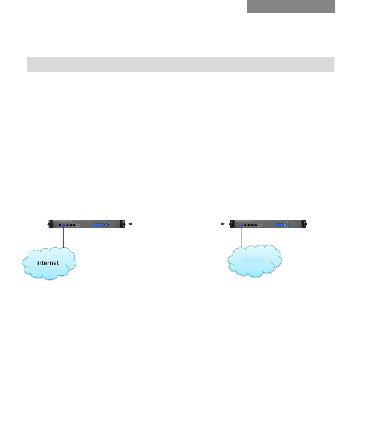
RaptorXR WS Digital Radio RaptorXR WS Digital Radio
Remote Station 1Base Station 1
Local LAN /
Subnet
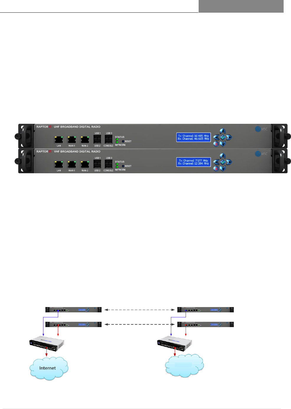
Figure 1.1: Basic RaptorXR Point-to-Point Backhaul Configuration

[RAPTORXR USER MANUAL VERSION 1.10]
May 2, 2017
20 | P a g e
POWER
AC Input
110/240 V AC 50/60 Hz
Maximum Power Consumption:
60 Watts
SECURITY
Encryption
128/256-bit Advanced Encryption Standard (AES)
Authorization and Accounting
Protects against unauthorized administration/maintenance and
over-the-air access
System access/authentication
capabilities
Multi-factor authentication. Remote access token-based
authentication
System access/authentication
capabilities
Integrated firewall and Information Assurance tools
NETWORK ARCHITECTURE
VLAN
Supports multiple laws; static and dynamic
System Integrity Logs
Firewall
Robust rule support and encrypted download
Dynamic ad hoc network
Adaptive, self-forming, self-healing network
Network Size
Limited only by available RF channels
Network capabilities/single channel
Point-to-point, point-to-multipoint and mesh
Network capabilities/ dual channel
Point-to-point, multipoint, and mesh
Maintenance/diagnostics
Over-the-air programming, integrated web-based
administration, monitoring and reconfiguration
System logs
System, security, authentication, information flow,
traffic monitoring and intrusion detection.
Network timing
Multiple network timing protocol options (NTP)
FREQUENCY STABILITY
Internal ±1.5 ppm
STANDARD ANTENNA INTERFACES
Common Tx/Rx antenna
ANTENNAS
Directional, Omni or Sector
[RAPTORXR USER MANUAL VERSION 1.10]
May 2, 2017
21 | P a g e
Optional System Features 2.3.1
Factory Default Configurations 2.3.2
FEATURES
DESCRIPTION
Diversity Option
P/N: DIV.1
Separate Tx and Rx antennas support the RaptorXR capability for spatial
and frequency diversity configuration. Provides up to 6 dB of system
margin for extended range and reliability in difficult NLOS urban and
rural applications.
GPS Location and
Frequency
Stabilization Options
P/N: GPS.1
Provides the user with the ability to automatically and accurately
provide the database provider with site location within ±50 meters and
altitude. Enables provider a highly stable frequency reference to the
RaptorXR’s RF subsystem to enable single channel use for outbound
broadcast and critical time of arrival applications.
FACTORY CONFIGURATION
BASE
REMOTE
Units
Low Band
High Band
Tx Frequency Down Link
(MHz))/CHANNEL
473/14
629/40
Rx Frequency Up Link
(MHz)/CHANNEL
629/40
473/14
Tx Bandwidth (MHz)
5
5
Constellation
4 QAM (QPSK)
4 QAM (QPSK)
Useful Data Rate (Mbps)
3.110
3.110
Full Duplex Rate
6.220
6.220
Code Rate (CR)
1/2
1/2
Guard Interval (GI)
1/4
1/4
Maximum Conducted Power
Output (dBm)
20
20
EIRP (dBm) with 10.15 dBi
antenna
30.15
30.15
PASSWORD
RaptorXR
RaptorXR
6-7
6-7
12 dBm
Tx Output Power to Antenna Adjusted
to meet Maximum Allowable EIRP
12 dBm
From Page 8
of Test
Report
[RAPTORXR USER MANUAL VERSION 1.10]
May 2, 2017
22 | P a g e
Theory of Operation
2.3.3
The RaptorXR system is a broadband full-duplex software-configurable radio capable
of operating in the High VHF 174 to 216 MHz TV band or the UHF TV bands 470-
698 MHz.
Platformed in a lightweight 19” 1U rack, the RaptorXR enables the network engineer
to deliver penetrating broadband coverage to a wide range of backhaul and edge
applications.
RaptorXR’s key performance element is the ultra-linear adaptive constellation digital
modulator. The digital modulator converts the incoming IP packets into error-
corrected data streams which are converted via a highly integrated software-
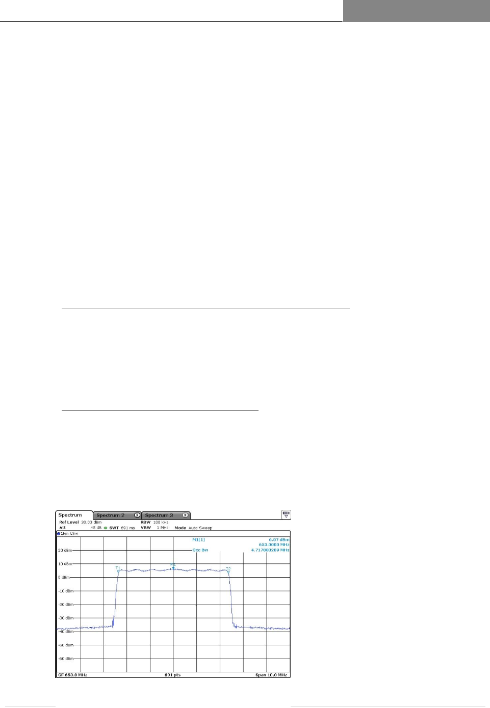
controlled Tx subsystem into VHF or UHF digital waveforms. Figure 1.15 below
illustrates the 5 MHz RaptorXR waveform used in domestic (US) White Space
applications.
Ultra-Sensitive High-Dynamic Range Broadband Receiver
RaptorXR’s proprietary broadband receiver technology optimizes operation in high
signal urban and RF co-site areas, while providing operation over an 80 dB-dynamic
range. In some cases, an external Rx filter may be required if operation is close to
high power, adjacent channel TV transmitters.
Ultra-Linear Broadband UHF Amplifier
RaptorXR’s Power Amplifier provides an ultra-clean low adjacent channel noise
amplified signal to Raptor’s low loss UHF TV band Duplexer. The power amplifier’s
efficiency allows the system designer to bond and aggregate channels to increase
effective useful throughput and redundant link operation.
FIGURE 1.A: 5 MHz Waveform
and
602
and the 626 to 698 MHz spectrum.

[RAPTORXR USER MANUAL VERSION 1.10]
May 2, 2017
23 | P a g e
Broadband UHF Duplexer
Full-duplex wireless operation requires, at minimum, two simultaneous clear
channels. In the RaptorXR one channel is called the Downlink Channel which
provides a broadband link from the Base Station to the Remote Station, using
channels in the low band segment of the duplexer. Conversely, the Remote Station
(Uplink) communicates with the Base Station on high-band channels. Table 5, page
58 provides a table of the low band and high band channels. The high efficiency
duplexer transitions from low band to high band in primarily unavailable channels.
Linux-Powered Multicore Network Processor
The R1020 RaptorXR Network Processor provides the user/operator with multiple
Ethernet and USB interfaces. The Ethernet interfaces are easily configured via
Raptor’s internal web page. The USB ports can support a wide range of Linux-based
applications. The RaptorXR is configured to support TP Links USB WiFi dongle.
The R1020’s encryption core supports a wide range of open source encryption
standards. Please contact Metric Systems for additional information on specific
application requirements.
[RAPTORXR USER MANUAL VERSION 1.10]
May 2, 2017
24 | P a g e
The RaptorXR Hardware Suite 2.4
The basic RaptorXR Hardware Suite consists of a Wireless Network Shelf and a
Broadband Antenna
Network Shelf – combines the RaptorXR software defined radio with versatile
software defined Network Processor and Network Interface Suite.
The RaptorXR Single Link White Space Channel Configuration includes one (1)
RaptorXR Network Shelf containing the local network processor and a single channel
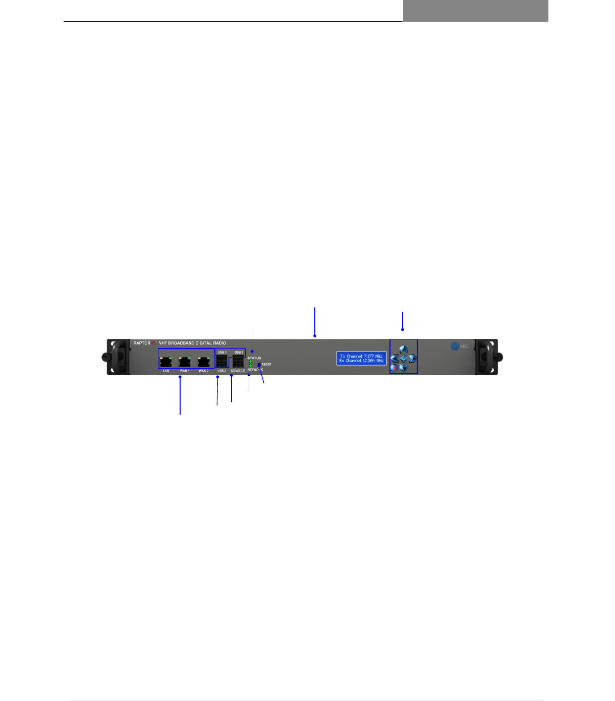
white space VHF/UHF broadband radio. Figure 1.1 below shows user indicators,
controls and physical interfaces of the Single Channel System. Figure 1.2 shows the
rear view of a Single Channel stack.
Network Processor Status
Processor Reset
Network Status
Front Panel
Navigation Keys
Front Panel Status
and Control Panel
Network Diagnostic
RS-232C Port
USB 2.0
Ports
10/100/1000Base-T
RJ-45 interface Ports
The front view ergonomics of all RaptorXR equipment are designed to provide the user and
installer with a minimum set of indicators and controls to monitor, operate and maintain
system operation following equipment registration.
Figure 1.2 Single Link System (Front View) illustrating user indicators, controls and physical interfaces.

[RAPTORXR USER MANUAL VERSION 1.10]
May 2, 2017
25 | P a g e
Network Shelf Front Panel Descriptions
2.4.1
ITEM
DESCRIPTION/FUNCTION
Front Panel Status and Control
Panel Display and Navigation Keys
Allows selection of available channels following
valid registration process
Allows setting of available power based on antenna
type and transmission line loss
Permits engaging of local or remote antenna-aiming
application (See Chapter 3)
System self-test
Enables and displays results of local and remote
equipment self-test
Enables maintenance mode for depot equipment:
calibration, diagnostics and repair. Password
protected.
Network Ports
One (1) local LAN port (See Chapter 4) (10/100/1G)
Two (2) WAN ports (See Chapter 4) (10/100/1G)
Three (3) USB ports are powered to support 250
MHz from each port, if required.
Indicates the RaptorXR is physically connected to
an external network Ethernet line. Yellow and
green LEDs indicate inbound and outbound
Ethernet packets transmission.
Network Diagnostic Port
Password controlled for factory and certified
professional use only.
Network Processor Status:
Blue (blinking)
Indicates processor and internal components are
operating Provides indication of local connectivity
to its (possible) adjacent RaptorXR unit and to the
core network gateway.
Network Status
Indicates the RaptorXR is connected to a valid IP
network and can reach RaptorXR’s FCC database
site.

[RAPTORXR USER MANUAL VERSION 1.10]
May 2, 2017
26 | P a g e
Processor Reset
Processor reset performs a warm reboot on the
network processor and TV band transceiver.
[RAPTORXR USER MANUAL VERSION 1.10]
May 2, 2017
27 | P a g e
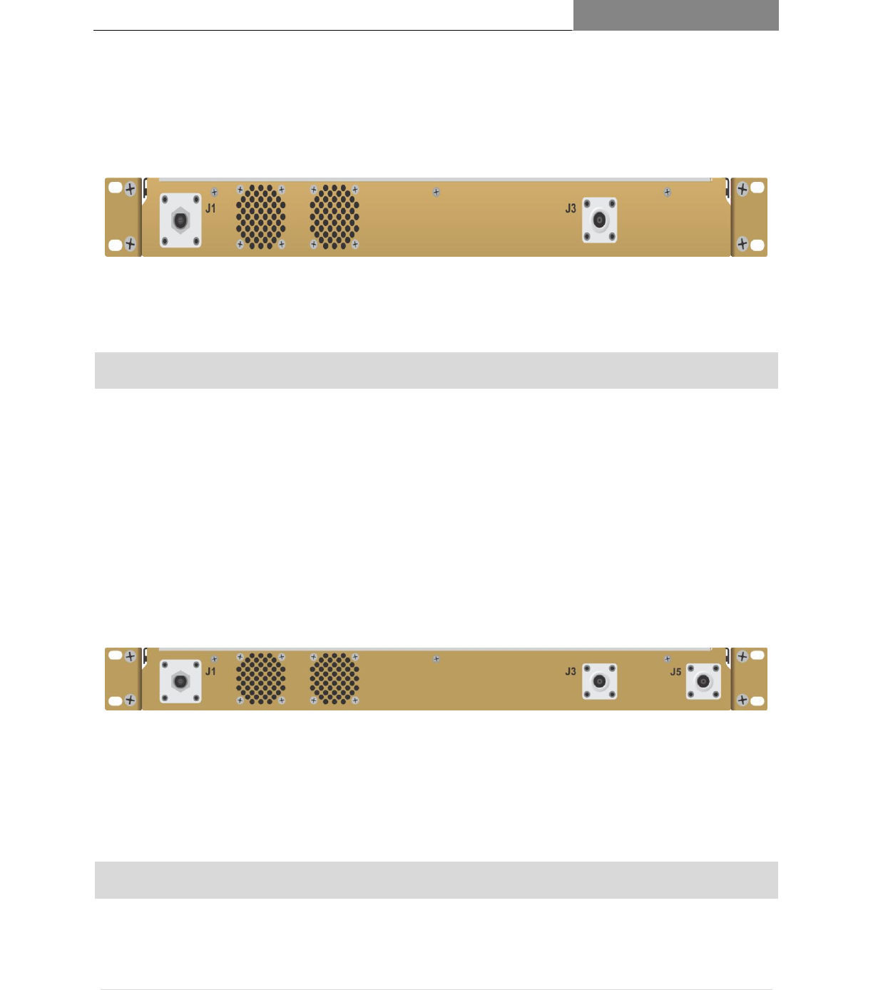
RaptorXR Single Link (Rear Views) 2.4.2
RaptorXR Single Link System (Rear Views) 2.4.3
RaptorXR Single Link Diversity System (Rear Views) 2.4.4
NETWORK SHELF ITEM
DESCRIPTION
J1:Power Input
DC Input: 12 and 28 V DC
J3:RF Tx/Rx Port
Tx/Rx Antenna
Type N Female
Dual Exhaust Fans
Keep Clear & Clean
NETWORK SHELF ITEM
DESCRIPTION
J1:Power Input
DC Input: 12 and 28 V DC
J3:RF Tx/Rx Port
Tx/Rx Antenna
Figure 1.3 Single Link System (Rear View)
Figure 1.4 Single Link Diversity System (Rear View)
[RAPTORXR USER MANUAL VERSION 1.10]
May 2, 2017
28 | P a g e
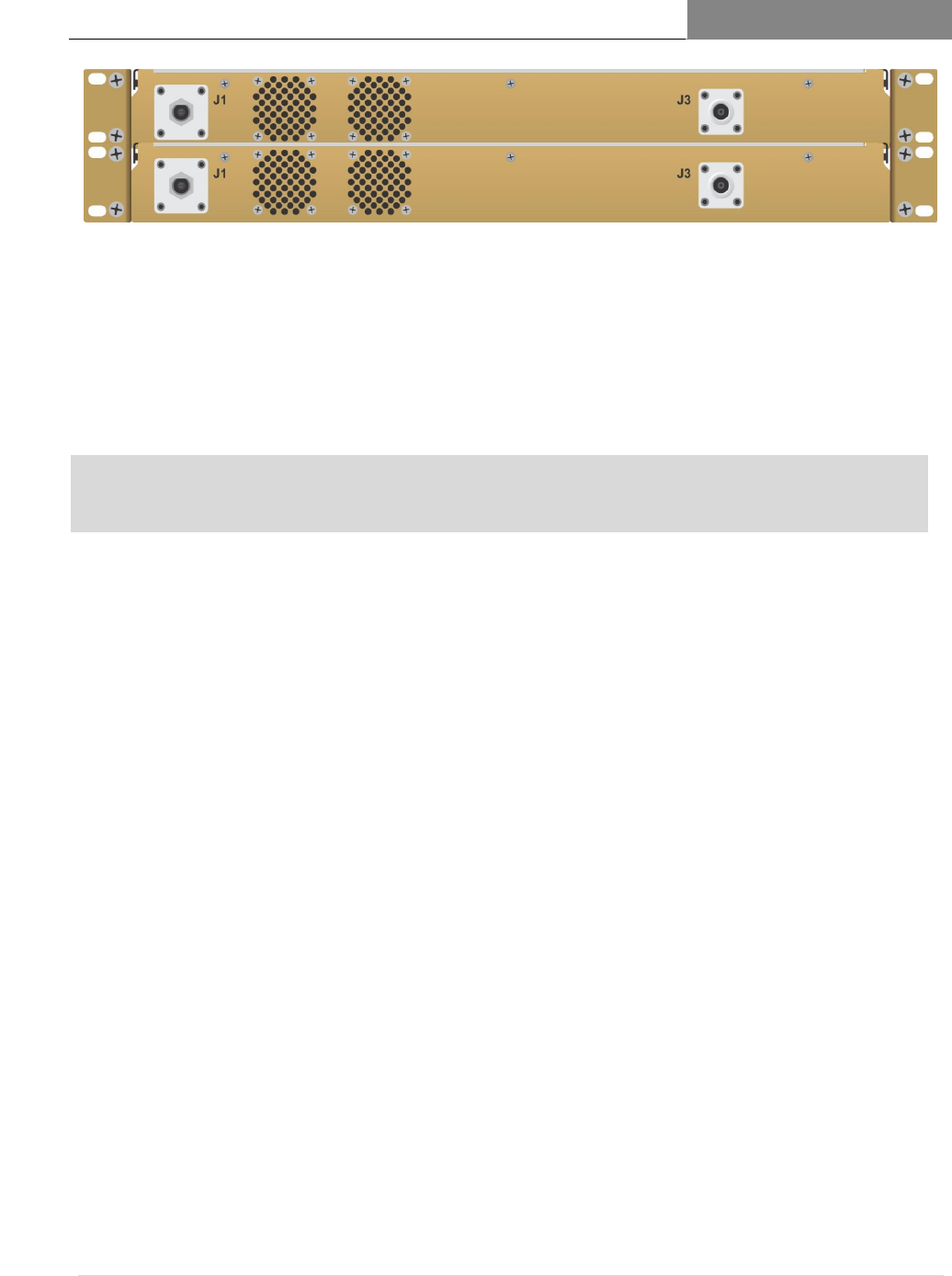
RaptorXR Dual Link Relay Configuration 2.4.5
A Dual Link RaptorXR System is configured by adding an additional Network Shelf...
Each independent Shelf contains one VHF or UHF White Space Tx/Rx unit.
2.4.5.1 Benefits of Dual Link System (See Figure 1.6)
Use of the Dual Link System provides the following system benefits and capabilities:
Increased link throughput capacity; nearly twice the rate of a single channel link
Fault-tolerant point-to-point link protection; connection is maintained in the event
of a channel propagation failure or a hardware failure
Spatial frequency and diversity
Wide area multiple sector point-to-multipoint networks
Back-to-back add-and-drop relay nodes for low latency long range relay chains
Figure 1.6 Dual Link System
Type N Female
J5 RF Tx/Rx Port
Tx/Rx Antenna
Type N Female
Air Intake and Exhaust Ports
Keep Clear & Clean
Figure 1.5 RaptorXR Dual Link System (Front View)
Full-Duplex Link 1
Full-Duplex Link 2
RaptorXR WS Digital Radio
Site 1
Base Station 1
RaptorXR WS Digital Radio
Site 2
Remote Station 1
Local LAN /
Subnet
Remote Station 2Base Station 2
Link Aggregation Switch
[RAPTORXR USER MANUAL VERSION 1.10]
May 2, 2017
29 | P a g e
RaptorXR Dual Link System using Channel Expansion Shelf Interfaces 2.4.6
CHANNEL EXPANSION
INTERFACES
DESCRIPTION
J1 DC Power Input- Mil-style
DC input from Power Supply
J3 RF Tx/Rx Output
Tx/Rx Antenna, Type N Female
Air Intake and Exhaust Ports
Keep clean and clear
Figure 1.7 RaptorXR Dual Link System (Rear View)

[RAPTORXR USER MANUAL VERSION 1.10]
May 2, 2017
30 | P a g e

[RAPTORXR USER MANUAL VERSION 1.10]
May 2, 2017
31 | P a g e
3 GETTING STARTED
Implementing a RaptorXR or network consists of three inter-related stages:
DESIGN
o Selecting operating channels via an FCC approved data base. (See below and
page
o Analytically validating that an operating link can be established (See page
DEPLOYMENT
o Locally registering and verifying RaptorXR operation (See page
o Deploy RaptorXRs to respective sites (Base or relay)
o Setting the RaptorXR link to an operational full-duplex rate. (See page
COMMISSIONING
o Testing the effectiveness of a link with actual data is possible with RaptorXR’s
embedded video server.
o Accessible via RaptorXR’s web page, streaming videos at various payload rates
can be selected, transmitted and monitored for path effectiveness.
EXAMPLE 3.1
This section describes the basics of setting up a Point-to-Point RaptorXR link. The example uses
actual locations and path design. For your particular application use local GPS coordinates.
This process will allow you to set up and confirm system operation prior to deployment. It is
assumed that all RaptorXR equipment, antennas and support accessories are available. Mobile
IP is a free radio link design application. It uses recently digitized topographic maps with land
coverage.
STEP 1: Selecting available White Space Channels (examples of GPS coordinates)
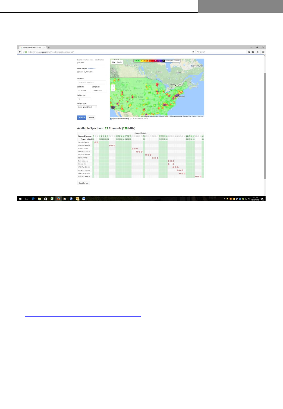
Using Google spectrum database: https://www.google.com/get/spectrumdatabase/index.html
STATION 1: Location: Pine Creek, MT Latitude: 45.52N Longitude -110.6253
Channels Available (total): 21 (126 MHz)
VHF High Band:
UHF: 14,15,16,17,18,30,31,32,33,34,35,43,44,48,49,50,51
STATION 2: Location: Carbella, MT Latitude: 45.25582N Longitude: -110.802

[RAPTORXR USER MANUAL VERSION 1.10]
May 2, 2017
32 | P a g e
Channels Available (total): 25 (150 MHz)
VHF High Band: 7,12
UHF Channels: 14,15,16,17,25,29,30,31,32,33,34,35,43,33,48,49,50,51
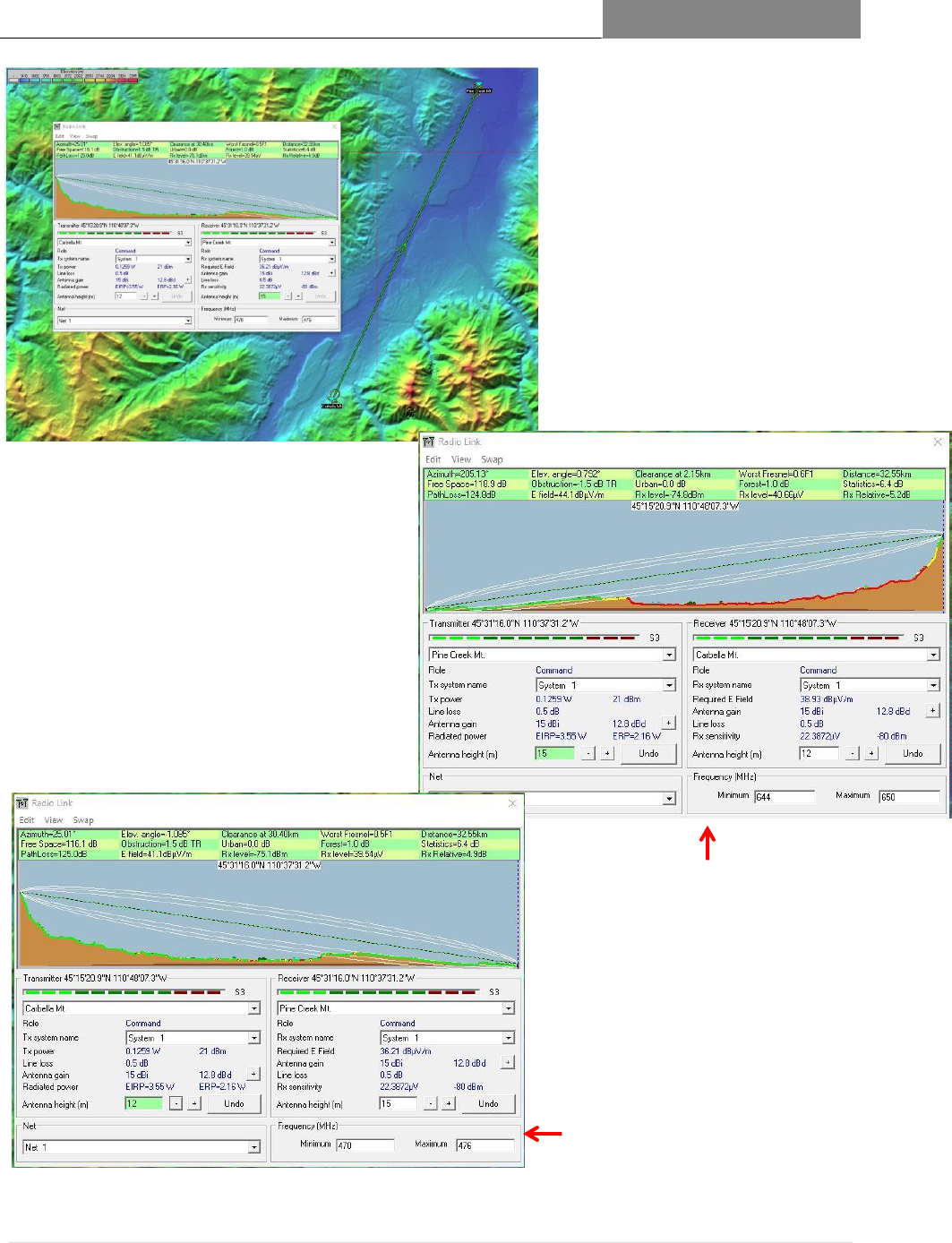
In this example the range between sites is 20 miles (32 mm). The Google database indicates
VHF High Band channels available at Carbella, but not at Pine Crest. We will choose the lowest
UHF channel available in the UHF low band spectrum (channels 14-35) and the lowest available
high band channel (channels 39-51).
From the database we will select Tx channel 14 for the Carbella to Pinecrest link;
And channel 42 for the uplink channel from Pinecrest to Carbella.
The figures below show the path statistics between each station: Key System Parameters are:
Point-to-Point Range: 32.55 km/20.35 miles
Tx EIRP Power: 3.55 Watts (35.5 dBm EIRP) (Maximum 4 Watts, 36 dBm EIRP)
Predicted Rx Signal Level: 70.7 dBm (using Langley-Rice model)
Projected Full-Duplex Data Rate: 30 mbps
Minimum Required Antenna Height: Pinecrest: 50 feet; Carbella: 40 feet
[RAPTORXR USER MANUAL VERSION 1.10]
May 2, 2017
33 | P a g e
This design clearly shows how a
reliable link is established between
two points, using available White
Space channels.
Practical aspects of the design include
antenna polarization (horizontal
recommended for rural, vertical for
urban) and additional losses in the
transmission system.
Figure 1.8 Topological and Point-to-Point
profile between Carbella and Pinecrest.
Figure 1.9 Point-to-Point profile of Pinecrest-
to Carbella link. Minimum Pinecrest
Antenna Height: 15 meters (50 feet.)
Antenna type: Kathrein PR-TV,15.5 dBd gain
Figure 1.10 Point-to-Point profile of
Carbella-to Pinecrest link. Minimum
Carbella Antenna Height: 12 meters (40
feet.)
Antenna type: Kathrein PR-TV,15 dBd gain

[RAPTORXR USER MANUAL VERSION 1.10]
May 2, 2017
34 | P a g e
4 Accessing VHF/UHF TV Band Spectrum
See Figure 1.7, Registering the RaptorXR, which shows the registration configuration of a
RaptorXR connected to the internet.
The RaptorXR only becomes operational when successfully registered with the RaptorXR’s
designated FCC certified database provider, Spectrum Bridge
http://whitespaces.spectrumbridge.com/whitespaces/home.aspx
Each domestic (U.S.) RaptorXR has been registered for one (1) year with Spectrum Bridge.
It is the operator’s responsibility to assure continued registration, either directly with a
certified database provider or through an MSC Service Plan.
To access the Registration page insert the IP address: 192.168.1.1 into your 4.1
web browser/URL line.
Insert required device and location information. Click Registration. 4.2
Upon a successful registration a list of available White Space channels will 4.3
be returned.
Select the appropriate TV channel to complete registration and activate the 4.4
Tx subsystem of the RaptorXR.
The remaining sections will describe in detail the Registration process. The 4.5
RaptorXR Database Registration Engine will automatically validate and re-
register the unit every 24 hours.

[RAPTORXR USER MANUAL VERSION 1.10]
May 2, 2017
35 | P a g e
5 RaptorXR Network Design Process
This section describes the process and tools required to design a RaptorXR White Space network.
Intermediate steps common to all professional radio system deployment will be left to the professional
designer and installer.
The major new elements in designing with White Space spectrum are:
Operating Channel Selection via an on-line secure database 5.1
Need to evaluate and predict link performance using an RF 5.2
System Planning application, e.g. Pathlink 5 or Radio Mobile.
RaptorXR certified radios, as shipped, are not pre-configured to 5.3
operate at any channel. The radios per FCC, Part 15 Subpart H
Rules must be successfully registered via the internet with a
certified FCC Database Provider. Metric Systems Corporation
has contracted with Spectrum Bridge.com (http://Spectrum
Bridge.com/spectrum-mgmt/white-spaces/index.html )for this
service.
Tools Needed: 5.4
Access to internet
Site parameters, i.e. GPS coordinates, intended Antenna Height
Spectrum or Signal Analyzer
PC or mobile device with appropriate browser.

[RAPTORXR USER MANUAL VERSION 1.10]
May 2, 2017
36 | P a g e
Step 1:DETERMINE LAT/LONG 5.5
Determine as accurately as possible the latitude and longitude of each probable antenna site. Use
these coordinates on the Google Spectrum Data Base
https://www.google.com/get/spectrumdatabase/index.html to determine available White space
channels at the site of each planned White Space antenna.
Enter latitude and longitude, along with device type. Fixed for RaptorXR and maximum antenna
height, 30 meters (98.4 feet). Click search for available channels.
You will be provided with all available channels for that site.
Site
Latitude
Longitude
# of Available Channels
(excluding Channels 2-
6)
Available Hi Band
VHF
Channels
Available UHF
Channels
Greenleaf, WI
44.31356
-88.09611
20
7-9, 13
14-19,32-35,44-47,51
McKenzie County,
ND
47.77910
-103.41576
34
13
16-35,39-51
Reno, NV
39.53087
-119.81390
4
10,11
39,41
Kuparuk Oil Field,
AL
70.05186
-150.06762
42
7-13
14-35,39-51
Permian Basin, TX
31.93900
-102.2276
12
11-13
14,16,28,34,44,45,47,48
Table 1: Example of Available Channels per Google White Space Database
[RAPTORXR USER MANUAL VERSION 1.10]
May 2, 2017
37 | P a g e
Figure 1.11 https://www.google.com/get/spectrumdatabase/index.html
Step 2: Selecting Available Channels to Use (using an RF Planning 5.6
Tool)
Several general guidelines should be used here:
Choose a channel/frequency (see frequency chart) that will provide you with sufficient
signal and fade margin to provide 99% worst case reliability expectation over the path
and range in which you will operate.
RaptorXR uses an adaptive modulation process that works to maximize data throughput
for a range of Rx signal levels vs local noise levels.
Radio Mobile, a semi-professional RF planning tool, can be downloaded from
http://www.cplus.org/rmw/english1.html. It is ideal for nearly all RF planning. If you
find it of value, please contribute.
[RAPTORXR USER MANUAL VERSION 1.10]
May 2, 2017
38 | P a g e
Step 3: Manually Setting Full Duplex Data Rate
5.7
The shipped default Useful Data Rate (UDR) of all RaptorXR radios is 3.110 mbps per
link direction (half-duplex) or 6.220 mbps full-duplex.
The RaptorXR has the capability of providing a high-end rate of 39.586 mbps full-duplex.
The Useful Data Rate (UDR) is a two- step process:
1. Using the Front Panel or the SafariView radio control page (see Fig…..)
Select: New Modulation Waveform Code Rate and GI parameters. The local
transmitter will automatically enable the remote Rx to sync to the higher (lower) rate.
2. If you are satisfied with resulting operation click, Apply: and the new rate will be
“locked” for that link direction. The reverse link can be remotely modified. It is not
necessary that each link have the same rate.
To maintain link reliability the RaptorXR uses an AI algorithm which monitors channel
C/N. If the algorithm senses the channel performance degrading it will attempt to
maintain communication by first increasing power, lowering transmission rate,
automatically moving to a new preassigned channel or entering into a channel scan mode
to discover a suitable pre-available channel.
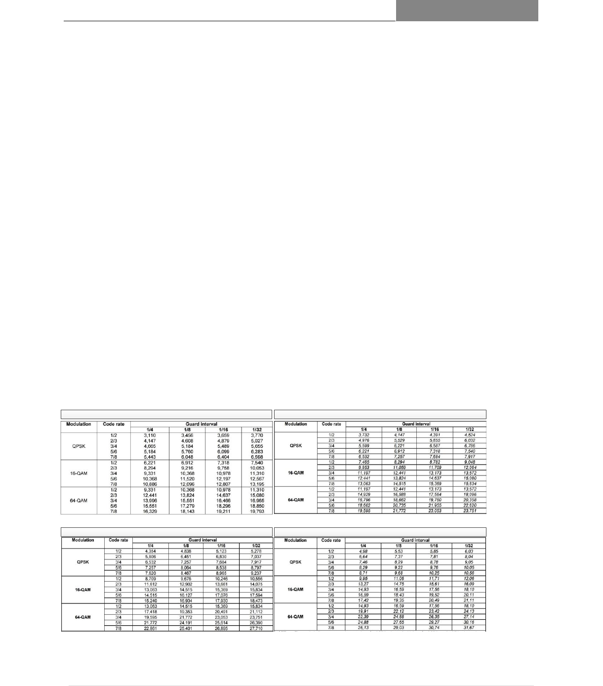
5 MHz Useful Data Rates per Waveform, Code Rate (CR) and Guard Interval (GI) settings 6 MHz Useful Data Rates per Waveform, Code Rate (CR) and Guard Interval (GI) settings
7 MHz Useful Data Rates per Waveform, Code Rate (CR) and Guard Interval (GI) settings 8 MHz Useful Data Rates per Waveform, Code Rate (CR) and Guard Interval (GI) settings
8 MHz Useful Data Rates 7 MHz Useful Data Rates
5 MHz Useful Data Rates 6 MHz Useful Data Rates
RaptorXR Single Channel Useful Data Rates as a Function of Code Rate (CR) and
Group Interval Setting
For full-Duplex Useful Rate add up-link and down link rates;
e.g. Up-link Rate 3.110 Mbps (QPSK, CR=½,GI=¼,
Down-link Rate 5.184 Mbps (QPSK, CR=¾,GI=1/8)
Total Full-Duplex Rate: 8.394 Mbps
Note Rate can vary a few percent due to signal-path, Processor andf Traffic Load
Table 2: Single Channel Useful Data Rates as a Function of Code Rate and Group Interval Setting

[RAPTORXR USER MANUAL VERSION 1.10]
May 2, 2017
39 | P a g e
NOTE 1: Quasi Error Free (QEF) means less than one uncorrected error event per hour, corresponding to
BER = 10-11
NOTE 2: The net bit rates after Reed-Solomon decoder are also listed.
Required C/ N for BER = 2 x 10⁻⁴
after Viterbi
QEF after Reed-Solomon
Bitrate (Mbit/s) Bandwidth = 5 MHz
Guard Interval
Modulation
Code
Rate
Gaussian
Channel
Ricean
Channel
(F1)
Rayleigh
Channel
(P1)
1/4
1/8
1/16
1/32
QPSK
1/2
3.1
3.6
5.4
3.110
3.456
3.659
3.770
QPSK
2/3
4.9
5.7
8.4
4.147
4.608
4.879
5.027
QPSK
3/4
5.9
6.8
10.7
4.665
5.184
5.489
5.655
QPSK
5/6
6.9
8.0
13.1
5.184
5.760
6.099
6.283
QPSK
7/8
7.7
8.7
16.3
5.443
6.048
6.404
6.598
16 -QAM
1/2
8.8
9.6
11.2
6.221
6.912
7.318
7.540
16 -QAM
2/3
11.1
11.6
14.2
8.294
9.216
9.758
10.053
16 -QAM
3/4
12.5
13.0
16.7
9.331
10.368
10.958
11.310
16 -QAM
5/6
13.5
14.4
19.3
10.368
11.520
12.197
12.567
16 -QAM
7/8
13.9
15.0
22.8
10.868
12.096
12.807
13.195
64-QAM
1/2
14.4
14.7
16.0
9.331
10.368
10.978
11.310
64-QAM
2/3
16.5
17.1
19.3
12.441
13.824
14.367
15.080
64-QAM
3/4
18.0
18.6
21.7
13.996
15.551
16.466
16.965
64-QAM
5/6
19.3
20.0
25.3
15.551
17.279
18.296
18.850
64-QAM
7/8
20.1
21.0
27.9
16.329
18.143
19.211
19.793
Table 3: Carrier to Noise (C/N) vs Useful Data Rate and Minimum Signal Required
[RAPTORXR USER MANUAL VERSION 1.10]
May 2, 2017
40 | P a g e
System Margin Examples
5.8
Link Budget Calculation 5.9
Link Budget Calculation
Down Link (Base to Remote)
Up Link (Remote to Base)
1. Operating Frequency ( MHz):
Operating Frequency ( MHz):
2. Tx Power (dBm):
Tx Power (dBm):
3. Transmission System Loss
Transmission System Loss
EMP Protector:
Coax Cable Loss:
Connector Loss:
EMP Protector:
Coax Cable Loss:
Connector Loss:
4. Antenna Gain (dBi):
Antenna Gain (dBi):
5. Tx EIRP (dBm):
Tx EIRP (dBm):
Down Link Path Loss
Up Link Path Loss
Range Miles:
Range Miles:
Path Loss PL = 36.6 + 20 log (F MHz) + 20 log
(d miles)
Path Loss PL = 36.6 + 20 log (F MHz) + 20 log
(d miles)
Up Link Rx Power
Downlink Rx Power
Rx = Tx EIRP + Rx Ant Gain – Path Loss
Rx = Tx EIRP + Rx Ant Gain – Path Loss
Rx signal must be greater than minimum signal (as required in 5.9 System Margin Table)
System Margin Examples
RaptorXR
VHF or UHF White
Space Transmitter
VHF or UHF
Antennna
VHF or UHF
Antennna
Transmission System
(Transmission Line,
EMP Device,
Connectors)
Path Loss
Frequency
Attenuation
Fading, etc.
Range
RaptorXR VHF or
UHF White Space
Digital Receiver
Maximum Conductive Tx
Power (6 MHz) dBm:
VHF: 25 dBm
UHF26 dBm
Typical Transmission System Loss Parameters
Connectorized 50 ‘ of LMR 600
@ VHF: .55 dB
@ UHF: 1.0 dB
Connectorized 100’ of LMR 600:
@ VHF: 1.1 dB
@ UHF: 2.0 dB
EMP Protector: .75 dB
Transmission System
(Transmission Line,
EMP Device,
Connectors)
Site 1
Site 2
Nominal White Space Antenna Parameters
VHF Antenna Gain: 6 dBi Directional Dipole with Reflector
UHF High Directivity Antenna Gain: 17.15 dBi
See Table for Minimum
Usable Signal Level per Band
and Waveform
Tx EIRP dBm
Minimum Rx Signal
(dBm) Required for
Waveform
10.15
[RAPTORXR USER MANUAL VERSION 1.10]
May 2, 2017
41 | P a g e
VHF Example:
System Gain and Margin calculations
VHF @ Channel 8, 183 MHz
PEIRP = Po (dBm) + VHF Tx antenna gain (6 dBi) = 31 dBm
Rx Antenna gain: 6 dBi, Rx System sensitivity: -104 dBm
VHF system gain @ 183 MHz= 31 dBm + 6 dBi + -104 dBm = 141 dB @ QPSK;
o CR: ½; GI: 1/8, FFT = 8K
System at each site introduces a 2 dB loss; SG = 141 – 4 dB = 137 dB
Path with loss of 125.0 dB provides an excess system margin of 12 dB.
The Radio Mobile program indicates a 4 dB margin with the ability to take into
consideration multipath, environmental effects and Tx/Rx antenna height.
Figure 1.12 VHF System Gain and Margin
[RAPTORXR USER MANUAL VERSION 1.10]
May 2, 2017
42 | P a g e
UHF Example:
System Gain and Margin Calculations:
UHF @ Channel 46, 665 MHz
PEIRP = Po (dBm) + UHF Tx antenna gain (10.15 dBi) = 36 EIRP dBM
Rx antenna gain: 10.15 dBi; Rx system sensitivity for 64 QAM: 100.4 dBm
o CR = ½; GI = 1/8; FFT: 8K
UHF System Gain @ 665 MHz = 36 EIRP dBm (Tx radiated power) + 10.15 dBi (Rx
antenna gain) + -100.4 = 146.55 dB
Let us say additional losses from system implementation, environmental and multipath
characteristics degrade the system margin by 6 dB, yielding an estimated margin of 140.5
dB.
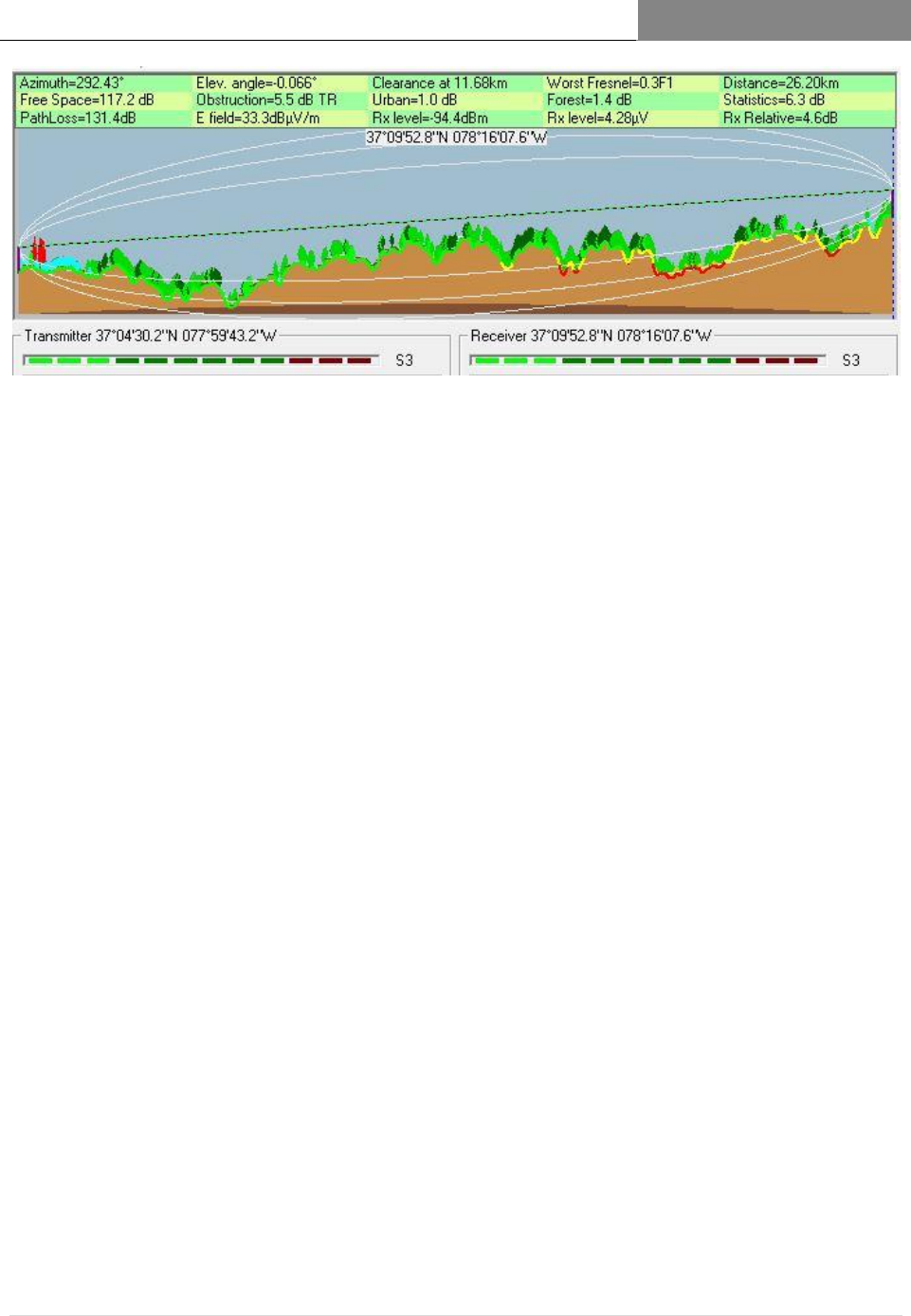
Again, using Radio Mobile (see Figure ) a 131.4 dB propagation loss is predicted
over a 26.2 km (16.375 mi) path over a deciduous broadleaf forest.
Thus system margin is:
o System Gain – Propagation Loss = System Margin
o 140.5 dB – 131.4 dB = 9.1 dB
This is the minimum acceptable one-way system margin. An additional _____dB of Rx margin
can be achieved with the PR-TV ParaReflector Antenna.
Figure 1.13 UHF System Gain and Margin

[RAPTORXR USER MANUAL VERSION 1.10]
May 2, 2017
43 | P a g e
System Margin Table
5.10
TABLE 4: SYSTEM MARGIN TABLE
RaptorXR Single Channel VHF/UHF Radio System (5 MHz CR: 1/2 GI: 1/4)
Tx Band
width
(MHz)
Tx
Wave-
form
UHF/
VHF
Bands
Tx Freq.
MHz
Min
Required
Rx Power
(dBm)1
System
Gain (dB)*
Req
C/N
(dB)
Useful
Data
Rate
(Mbps)
Full
Duplex
Rate
Code
Rate
(CR)
Guard
Interval
(GI)
Number
of
OFDM
Carriers
(FFT)
5
QPSK
VHF
183
-104.0
141.0
3.1
3.110
6.220
1/2
1/4
8K
5
QPSK
UHF
473
-105.2
158.4
3.1
3.110
6.220
1/2
1/4
8K
5
QPSK
UHF
656
-105.4
158.6
3.1
3.110
6.220
1/2
1/4
8K
5
16QAM
VHF
183
-99.5
136.5
9.1
6.221
12.442
1/2
1/4
8K
5
16QAM
UHF
473
-105.2
158.4
9.1
6.221
12.442
1/2
1/4
8K
5
16QAM
UHF
656
-105.6
158.8
8.8
6.221
12.442
1/2
1/4
8K
5
64QAM
VHF
183
-104.7
141.7
13.7
9.331
18.662
1/2
1/4
8K
5
64QAM
UHF
473
-100.7
153.9
14.1
9.331
18.662
1/2
1/4
8K
5
64QAM
UHF
656
-100.4
153.6
13.6
9.331
18.662
1/2
1/4
8K
5
64QAM
VHF
183
-86.2
133.35
20.1
19.793
39.586
7/8
1/32
8K
5
64QAM
UHF
473
-92.0
145.15
20.0
19.793
39.586
7/8
1/32
8K
5
64QAM
UHF
656
-94.0
147.0
20.0
19.793
39.586
7/8
1/32
8K
*UHF TX = EIRP 36 dBm; Rx Ant: 17.15 dBi; VHF = EIRP 31 dBm; Rx Ant: 6dBi
NOTES:
5.10.1
• System Gain = Tx EIRP (Far End dBm) - minimum sensitivity for QEF BER of 10-11 + Rx Antenna-gain
dBi
• Nominal VHF conductive output power of 25 dBm with a nominal 6 dB Tx and Rx directional gain
antenna for an EIRP of 31 dBm.
• Nominal UHF conductive output power of 26 dBm with a 10 dBi antenna
• QEF = Quasi error-free means less than one uncorrected error event per hour corresponding to BER
= 10-11
• Effective Tx Antenna system gain and Rx Antenna System gain are adjustable. For example: If one is
using a 15 dBd (17.15 dBi) Directional Antenna, upon registration and selection of this antenna the spectrum
database will determine whether to limit EIRP power to either 36 dBm EIRP or 40 dBM EIRP (22.85 dBm). The
RaptorXR will compensate for inline transmission losses. Thus on the Tx channel, maximum power limits are
observed, but the Rx is using the full antenna gain, in this case 17.15 dBi.
1
Actual sensitivity is affected by local in-band and adjacent channel noise. A 10 dB margin on all links is
recommended for sustainable reliability.

[RAPTORXR USER MANUAL VERSION 1.10]
May 2, 2017
44 | P a g e
Antennas
5.11
The RaptorXR is certified to operate with the following VHF and UHF antennas to fit various
deployment scenarios. When you register the RaptorXR you will be required to include on the
Registration Application the chosen antenna, including the height and latitude and longitude
center. This information will be used to automatically configure the RaptorXR to provide peak
link performance. (See Section 6.2 for antenna details.)
VHF –TV Panel Antenna -174-230 MHz (P/N AVPA230)
UHF-TV Log Periodic Antenna 470-862 MHz (P/N AUPE 862)
UHF High Gain Semi-Parabolic Antenna - 470-862 MHz (P/N AUPRTV862)
Rx mode only. Tx automatically limited to EIRP of 36 dBm.
UHF- Corner Reflector Sector Antenna – 470-800 MHz ( P/N ARS800EU)
Transmission System (Transmission Line + EMP Protectors) 5.12
We recommend that a Low-Loss LMR-600 coaxial cable with waterproof connectors be
used.
K523157)
CL 1469B)

[RAPTORXR USER MANUAL VERSION 1.10]
May 2, 2017
45 | P a g e
6 RaptorXR Data Base Registration
and Channel Selection Procedure
This guide supports pre-deployment procedure required of RaptorXR VHF/UHF Radio Units for
proper registration with the Spectrum Bridge Database to comply with FCC: CFR47 PART 15
SUBPART H Database Registration Requirements. FCC rules require that all White Space
radios securely access an FCC-certified database via the internet to verify channel availability. In
this instruction, RaptorXR units designated as a “BASE” have a direct connection to the internet.
Units described as a “REMOTE” do not have a direct connection to the internet, thus require a
secure radio link to a “BASE” in order to access the internet. The “BASE” provides secure
routing services to transport traffic to and from the internet for the “REMOTE” unit. Both the
BASE and the REMOTE units need to be independently registered prior to channel assignment
and/or site deployment. Sections 3.4 to 3.11 provide detailed descriptions of FCC requirements
and RaptorXR set up and registration procedures.

[RAPTORXR USER MANUAL VERSION 1.10]
May 2, 2017
46 | P a g e
Configuration and Registration Instructions Prior to Deployment
6.1
Setup the units as illustrated in Figure 1.5A. The registration process requires that 6.1.1
RaptorXR units be setup together and connectivity be established between the two units. If
required, individual units can be configured and tested separately. When configuring the
REMOTE units, FCC requires that it be permanently connected to a BASE station via a
virtual radio link. REMOTE units require a temporary direct connection to the internet to
be independently registered prior to operation or testing.
Once the units are setup per Figure 1.5A,.apply power to both units and to any additional 6.1.2
required equipment (e.g. laptop, switches, routers, spectrum analyzer, etc.). Allow all
equipment to fully boot and enter normal operation. At a minimum, please allow all
equipment to stabilize for 15-30 minutes.
Use the Spectrum Bridge website to determine the available channels each deployment 6.1.3
site. Establish an internet connection to the desktop or laptop pc. Open an internet
browser window. Type the following URL in the search bar and press enter:
http://whitespaces.spectrumbridge.com/whitespaces/home.aspx
Click the “Enter Location” button on the bottom left of the page. A window will open for 6.1.4
you to enter the proposed antenna coordinates and click the Apply button. A new map of
the requested area opens and the available channels are shown on the right side of the
page.
Record the site coordinates and desired available operating channel on the Raptor XR 6.1.5
Radio Configuration Worksheet. Do this for each unit that is to be configured. A
REMOTE unit’s Tx channel must be available at both the BASE and REMOTE
locations. Multiple BASE and REMOTE radio units need to be independently registered
each at their independent deployment locations.
Disconnect the temporary internet connection from the desktop or laptop pc and 6.1.6
reconnect to each respective RaptorXR as shown in Figure 1.5A.
Configure each RaptorXR Unit for operation by opening a browser window on the desktop 6.1.7
or laptop pc that is connected as described in the Setup Diagram. If registering a
REMOTE unit connect a temporary internet connection as described in the setup
diagram. Type the units IP address in the search bar and hit enter. This will take you to
the RaptorXR Radio browser page.

[RAPTORXR USER MANUAL VERSION 1.10]
May 2, 2017
47 | P a g e
On the left side of the page go to the SYSTEM ADMIN tab and select SYSTEM
6.1.8
CONFIGURATION from the popup menu.
Login using the following information: 6.1.9
Username: root Password: mscadmin (lowercase)
Displayed across the upper part of the page are a series of menu tabs. Go to the TVBD 6.1.10
tab and select TVBD1 from the dropdown menu.
Enter in all the required information in the appropriate fields. See the RaptorXR Radio 6.1.11
Configuration Worksheet for the unit specific information. The FCC ID and SERIAL
NUMBER are fixed and cannot be changed. Enter the coordinates of the operating site
location in which the unit will be deployed. Enter antenna height, gain, and transmission
line loss in the device information box. Next enter in the CONTACT and
REGISTRATION information (all fields must be filled in). Next enter in the
INSTALLER information. The installer information is from the person/company setting
up the unit for operation in the field. Once all the information is typed in, click the
REGISTER DEVICE button at the bottom of the page.
The unit will now verify the correct information was entered and request registration 6.1.12
from the FCC database over the internet. If successful, the page will ask you to select an
operating channel from the CHANNEL LIST field in the location box. The channel list
will only show the available channels for the geo-location coordinates entered for that
unit. Once registered location coordinates cannot be changed without unregistering the
unit. Units can switch to another available channel at any time. Select an operating
channel from the list.
You are now registered to that channel. Next select the YES option in the ENABLE 6.1.13
RADIO field in the Radio Information box. Click the START RADIO ON STARTUP
checkbox and then click the APPLY CHANGES button. This turns the unit’s radio on
and enables the selected channel for normal operation.
The Unit is now set up and registered to the FCC Database for operation on the selected 6.1.14
channel. If the Unit is equipped with a second radio channel (Expansion Shelf) go to the
TVBD menu tab and select TVBD2 from the drop down menu. Repeat steps 6 thru 12 to
register the second radio. The second radio (TVBD2) must have the same location
coordinates as the TVBD1 radio since they are in the same stack and will be installed at
the same location. Select a different operating channel for the unit’s second radio.
Repeat the above configuration and registration instructions for each RaptorXR Radio Unit
to be deployed and tested.

[RAPTORXR USER MANUAL VERSION 1.10]
May 2, 2017
48 | P a g e
Procedure for Unregistering a RaptorXR and Relocating to Another 6.2
Location
TVBD Units are only authorized to operate at a specific geo-location using available data 6.2.1
base channels. To relocate a Unit to another location you must first unregister the Unit.
This requires the Unit be directly connected to the internet. See setup diagram in Figure
1.12A,
Follow steps 3.1.7 thru 3.1.10 described above to navigate to the TVBD Configuration 6.2.2
page. The TVBD page will automatically detect current registration and available
channels. Scroll down to the bottom of the page and click “ UNREGISTER DEVICE”.
The Unit will now unregister itself from the FCC Database. Once successfully
unregistered, the device will automatically turn off the associated radio.
At the new location enter the NEW location coordinates and any other information that 6.2.3
has changed pertaining to the NEW location (i.e. antenna height, gain, transmission line
loss). Verify all other information is correctly filled in then click the REGISTER
DEVICE button at the bottom of the page. Select the new operating channel from the
available channel list when prompted. The Unit is now registered to a new location and
channel.
Activate the radio by clicking APPLY CHANGES in the radio information box. Be sure 6.2.4
to select YES in the ENABLE RADIO field and select the START RADIO ON
STARTUP option before clicking APPLY CHANGES.
The Unit will now begin normal operation on the new channel and location. 6.2.5
If the Unit is equipped with a second radio then repeat steps 3.2.2 thru 3.2.5 selecting the 6.2.6
TVBD2 tab this time from TVBD drop down menu.
Repeat the Unit Relocation Instructions for additional Radio Units. 6.2.7

[RAPTORXR USER MANUAL VERSION 1.10]
May 2, 2017
49 | P a g e
Instructions for Checking Available Channels using the Google
6.3
Spectrum Database or the Spectrum Bridge Database.
Identifying available White Space channels for the continental United States or its possessions is
done by using the Google Spectrum Database or the Spectrum Bridge website’s CHANNEL
AVAILABILITY feature.
On a Desktop or Laptop computer with a direct connection to the internet, open an 6.3.1
internet browser window and type URL below to access the
Google Spectrum Database https://www.google.com/get/spectrumdatabase/index.html
or the
Spectrum Bridge home page.
http://whitespaces.spectrumbridge.com/whitespaces/home.aspx
You must type the entire URL.
Now click the CHANNEL AVAILABILITY link or the map in the middle of the page. 6.3.2
You can click anywhere on the map to view channel availability at that location or you
can click the ENTER LOCATION button on the bottom left of the page and enter the
specific GPS coordinates in the popup window and click the APPLY button. The new
location is displayed on the map and the available channels are on the right of the page.
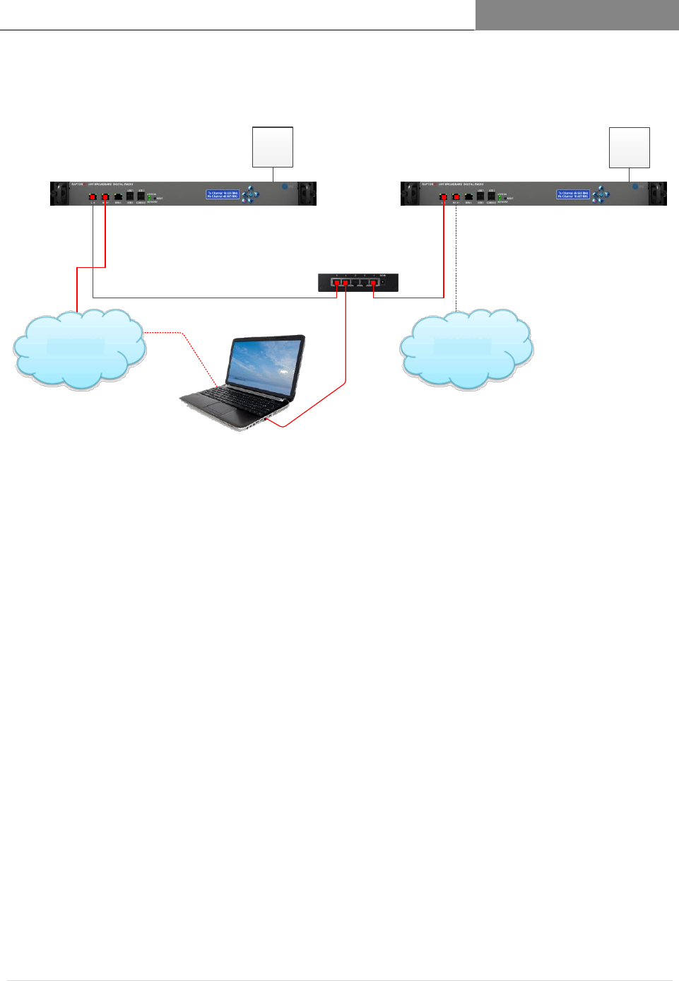
[RAPTORXR USER MANUAL VERSION 1.10]
May 2, 2017
50 | P a g e
Figure 1.14Set Up Configuration for Registration
Site 1
Base Station 1
Site 2
Remote Station 1
Internet Internet
50 Ohm
Dummy
Load for
Testing
50 Ohm
Dummy
Load for
Testing
Switch

[RAPTORXR USER MANUAL VERSION 1.10]
May 2, 2017
51 | P a g e
The RaptorXR TV Band Device (TVBD) has two status modes:
6.4
“Unregistered” and “Registered”.
When valid registration settings are detected 6.4.1
an attempt is made to load the configuration. Upon successfully loading, an
automatic check is performed to determine the mode (see definitions below) and
that the appropriate form fields are displayed for the proper mode.
Unregistered mode: 6.5
All fields (excluding address 2) under Device, Location, Contact, and Registrant must be
completed with valid information (see pg. 7). Once completed the device must be
registered by clicking the ‘Register Device’ button. If an error is detected registration will
fail and a notification with the appropriate error(s) will be shown. In the event of an error
the device will stand-by for correct input before successfully switching to registered mode.
Registered mode: 6.6
Upon successful registration, a list of available white space channels is returned in the
“Channel List” drop-down menu and the device prompts to select a channel. When a
channel has been selected the device does an additional check with the FCC database to
ensure it is still available and proceeds with the channel registration. At any point the user
may choose to refresh the ‘Available Channel’ list or ‘Unregister’ the device by clicking
the desired button.
Radio Transmission: 6.7
After successfully registering a radio to a channel frequency the final step is to enable radio
transmission. To do so, fill out all input fields under the Radio Information and set Enable
Radio to the Yes Option. If the device should enable the radio on startup, check the
appropriate box as well. Click the ‘Apply Changes’ button to commence RaptorXR radio
operations

[RAPTORXR USER MANUAL VERSION 1.10]
May 2, 2017
52 | P a g e
To change any information after registration 6.8
the device must first be in the unregistered state. To do so, simply click the Unregister
button.
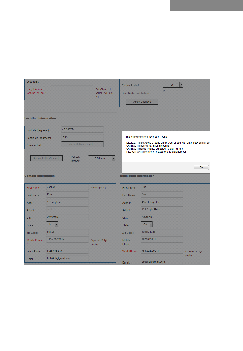
[RAPTORXR USER MANUAL VERSION 1.10]
May 2, 2017
53 | P a g e
Completing the RaptorXR Registration Form
6.9
When filling out the fields to register the RaptorXR they are automatically scanned for
errors
2
when attempting to register the device. If any errors are caught they are displayed
and marked along with the appropriate error message. Below is an example of some
errors as well as a brief explanation of what to enter for each field.
1 – Error Descriptions
1. Syntax – Invalid characters appear or the format is wrong
2. Out of Bounds – Input is not in the correct range (too high or too low)
3. NIL Input - No Input in a field
4. Channel Registration – The TV channel is not valid for registration
5. Device Registration – Registration failed
6. Radio Registration – The radio settings were not successfully applied
Figure 1.15 RaptorXR Registration Form
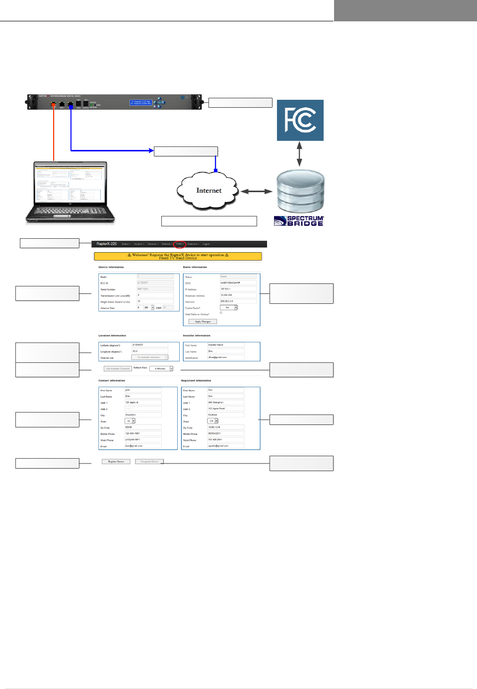
[RAPTORXR USER MANUAL VERSION 1.10]
May 2, 2017
54 | P a g e
Registering the RaptorXR
6.10
Access Registration Page via Web
Browser @ 192.168.1.1
Installer/maintenance
contact information
To access available channels,
provide deployment site
location
Provide basic site
deployment information
Click to complete registration
A list of available channels will
be provided
Figure 1.16 RaptorXR Registration Configuration Set-Up
RaptorX ID set at factory
RaptorXR Network Controller
Connection to the network
Secure link transparent to user
Basic radio network
information; factory default
information shown
Sets channel availability
refresh rate
Owner of RaptorX equipment
Unregisters device for RaptorX
relocation and/or servicing
Certified FCC Database

[RAPTORXR USER MANUAL VERSION 1.10]
May 2, 2017
55 | P a g e
[DEVICE]
6.10.1
Radio: The device radio number | This is locked into the RaptorXR at manufacture
FCCID: The device FCC ID | This is locked into the RaptorXR at manufacture
Serial Number: The device serial number | This is locked into RaptorXR at manufacture
Antenna Gain: The antenna gain power (dBi/dBd) | Expected: [-15, 15]
Transmission Line Loss: Measured transmission line loss (dB) | Expected: [0, 10]
Antenna height above ground level (HAGL): (m) | Expected [0, 30]
EIRP: The Effective Isotropic Radiated Power output | Locked into RaptorXR
, MAX=36
[LOCATION] 6.10.2
Latitude: The latitude up to six decimal places (degrees) | Expected: [-90, 90]
Longitude: The longitude up to six decimal places (degrees) | Expected: [-180, 180]
Channel List: The list of available TV channels | Determined by geolocation
[RADIO] 6.10.3
Status: The radio status | Will display ‘Up’ or ‘Down’ dependent on operation mode
SSID: The broadcast SSID | Accepts all characters except [ ><&\”=/ ]
IP Address: The radio IP Address
Broadcast Address: The radio Broadcast Address
Subnet mask: The radio subnet mask
[CONTACT/REGISTRANT] 6.10.4
*The contact form information should be that of the owner of the device.
*The registrant form information should be that of the installer’s for troubleshooting.
*The contact and registrant can be the same in some cases
*Fill out the forms with the appropriate corresponding label information. No special
cases.
[MISC] 6.10.5
Refresh Interval: How often the registered channel and list of available channels are
checked for availability (refreshed). Recommended period: 5 minutes
Enable Radio: Enable or disable the corresponding radio unit; either Radio 1 or Radio 2
Startup?: Enable or disable the corresponding radio unit when the device starts up (If
enabled, the RaptorXR will begin sending beacon packets to alert other RaptorXR nodes
operating on a common channel within the network.)
Get Available Channels: Refreshes the list of available TVBD channels
Register Device: Uses the information to register the RaptorXR
Unregister Device: Unregisters the RaptorXR
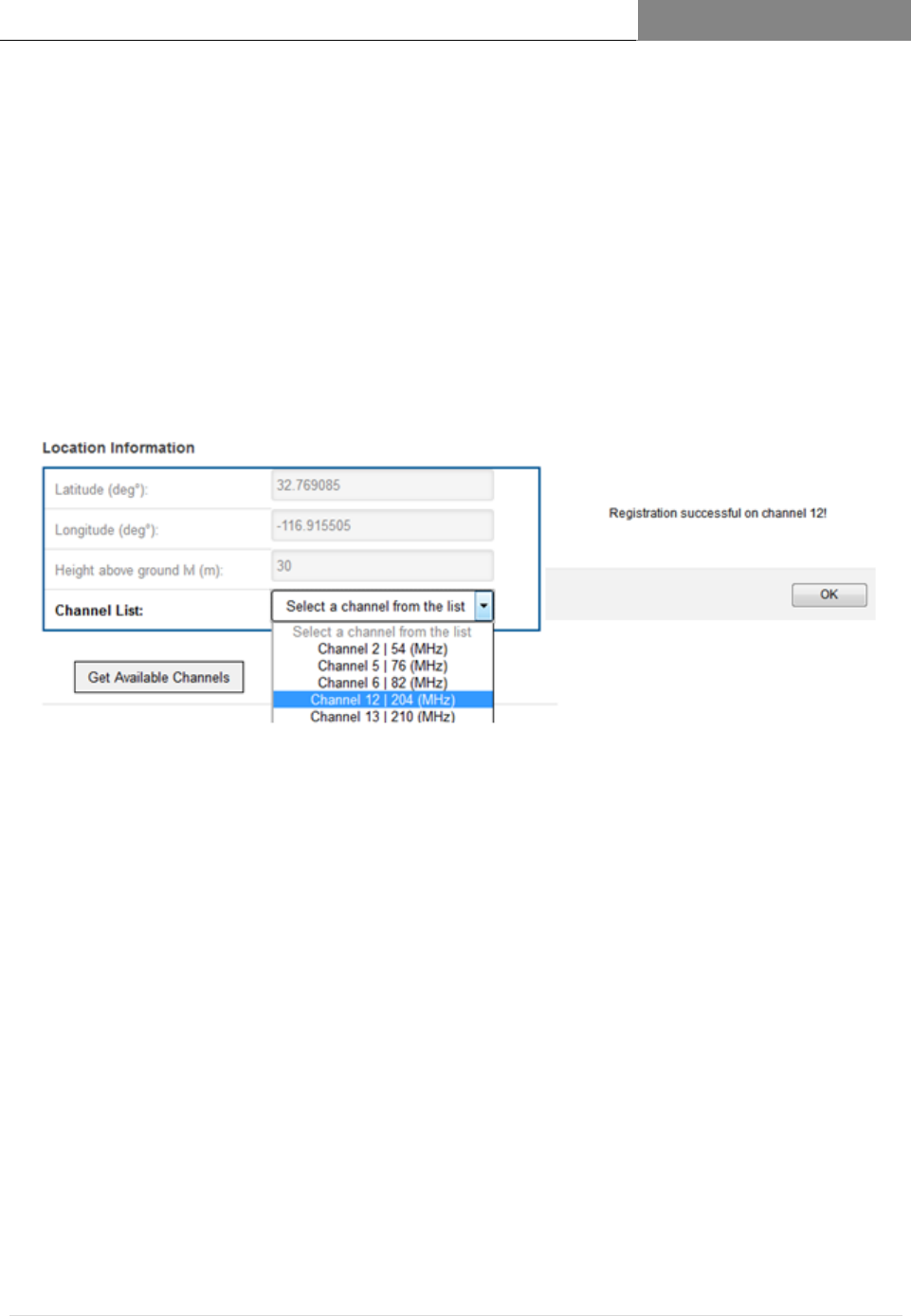
[RAPTORXR USER MANUAL VERSION 1.10]
May 2, 2017
56 | P a g e
The RaptorXR must be unregistered when:
o RaptorXR is moved beyond 50 meters from its current operating location.
o It is being repaired or undergoing firmware upgrades.
Upon a Successful Registration: 6.11
6.11.1.1 All the fields are locked and prevented from being modified;
6.11.1.2 TV channel list is available with the geographically available channels. To assign
the device to an available channel simply select the desired channel from the
drop-down list.
6.11.1.3 While the RaptorXR is registered the list of available channels can be refreshed at
any point by clicking the ‘Get Available Channels’ button.
6.11.1.4 After registering a valid TV channel the radio is now ready for operation. To
begin, complete the ‘Radio Information’ form and ensure the ‘Enable Radio’
option is set to “Yes”. Click on ‘Apply Changes’, the RaptorXR device will
complete the registration and start radio operation on the appropriate TV
channel. In the sample above we have selected TV Channel 12, center frequency
204 MHz
6.11.1.5 If any issues occur go back to the first step and follow the instructions carefully.
6.11.1.6 To unassign a channel but keep the RaptorXR registered simply select the first
option in the drop-down list that reads ‘Select a channel from the list’ (colored
grey).
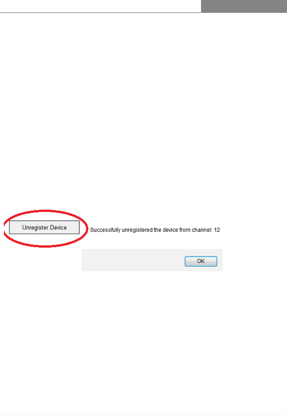
[RAPTORXR USER MANUAL VERSION 1.10]
May 2, 2017
57 | P a g e
Unregistering the RaptorXR 6.12
When the device is in registered mode the ‘Unregister Device’ button 6.12.1
becomes enabled
If the device needs to go into the unregistered mode the user must press 6.12.2
the ‘Unre57gister’ button
Unregistering the RaptorXR will send it back to unregistered mode after 6.12.3
successfully dropping the registered channel followed by completely
unregistering the device.
*To change any fields the device must be in unregistered mode.
*Unregistering the device will allow changes to all form information

[RAPTORXR USER MANUAL VERSION 1.10]
May 2, 2017
58 | P a g e
TABLE 6: UHF
Frequency Range
TV Channel
Number
Center
Frequency
(MHz)
UHF Low Band
470-599 MHz
Channels 14-35
14
473
15
479
16
485
17
491
18
497
19
503
20
509
21
515
22
521
23
527
24
533
25
539
26
545
27
551
28
557
29
563
30
569
31
575
32
581
33
587
34
593
35
599
Channel 36-39
Band Split
39
623
UHF High Band
629-698 MHz
Channels 40-51
40
629
41
635
42
641
43
647
44
653
45
659
46
665
47
671
48
677
49
683
50
689
51
695
TABLE 5: VHF
Frequency Range
TV
Channel
Number
Center
Frequency
(MHz)
VHF Low Band
177-189 MHz
Channels 7-9
7
177
8
183
9
189
Channel 10 – Band
Split
10
195
VHF High Band
201-213 MHz
Channels 11-13
11
201
12
207
13
213

[RAPTORXR USER MANUAL VERSION 1.10]
May 2, 2017
59 | P a g e
Appendix 1 Communications Protocol between the TVBD and the
6.13
Certified FCC Database
1. What communication protocol is used between the database and the TVBD?
The TVBD connects to the Spectrum Bridge database using HTTP over SSL/TLS. The protocol used
over this transport layer is specified by the IETF Protocol to Access White Space (PAWS) Draft-12
specification.
2. How are communications initiated?
The TVBD initiates communication with the Spectrum Bridge database by first sending an
INIT_REQ message containing a Device Descriptor. The Device Descriptor element contains the device
serial number, manufacturer ID, and model ID, which in the US is the FCC ID.
3. How does the TVBD validate messages from the database?
The identity of the Spectrum Bridge database is validated through verification of the Spectrum Bridge
SSL certificate through standard third-party certificate authority mechanisms, ensuring the
communications are secure and authentic between the TVBD and the database.
At the application layer both the TVBD and database only handle messages that conform to the
PAWS (Protocol to Access White Space) specification. One additional message validation feature
included in PAWS is the ability for the TVBD to correlate a response with a specific request by
comparing the message’s ID field with the ID field of the request that was sent.
4. How does the device handle failure to communicate or authenticate the database?
If the TVBD has never communicated with or authenticated the database, then it will not begin
operation. If once operating, experiences a communication or authentication failure, then it will cease
operation at 11:59 PM on the following day.
5. How does the database validate messages from a TVBD?
The database validates messages from the TVBD by checking the serial number and FCC ID received
in the Device Descriptor data element in every message versus a table of valid client devices that is
populated when the device is manufactured. The list of valid serial numbers is communicated from device
manufacturer to Spectrum Bridge via “out-of-band means,” such as email or telephone.
6. What encryption method is used?
SSL/TLS standard encryption is used to encrypt packets sent and received between the TVBD and
database.
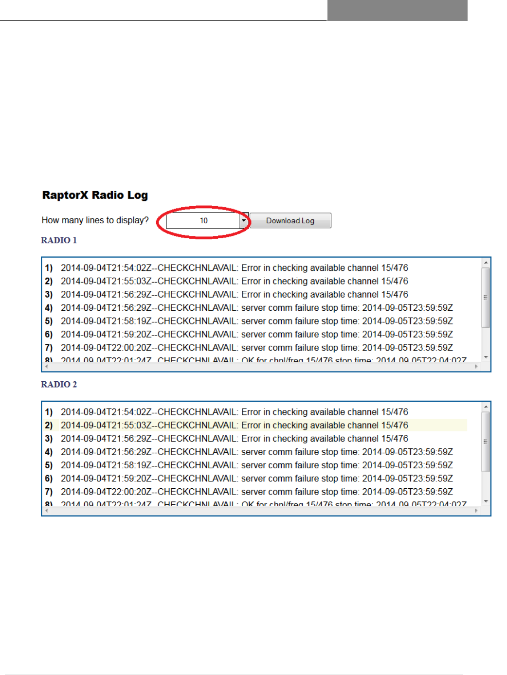
[RAPTORXR USER MANUAL VERSION 1.10]
May 2, 2017
60 | P a g e
Appendix 2 Logging
6.13.1
When the RaptorXR successfully executes certain operations (registering channel, checking channel
availability, etc.) the output of the execution is sent to a log file. This log file can be displayed on the
“Radio Logging” page.
The output of the logs is the most recent N lines of the log file where N is the number in the drop-
down selector outlined in red below. If the entire log is needed there is a “Download Log” button which
will securely download the log file for the radio(s).
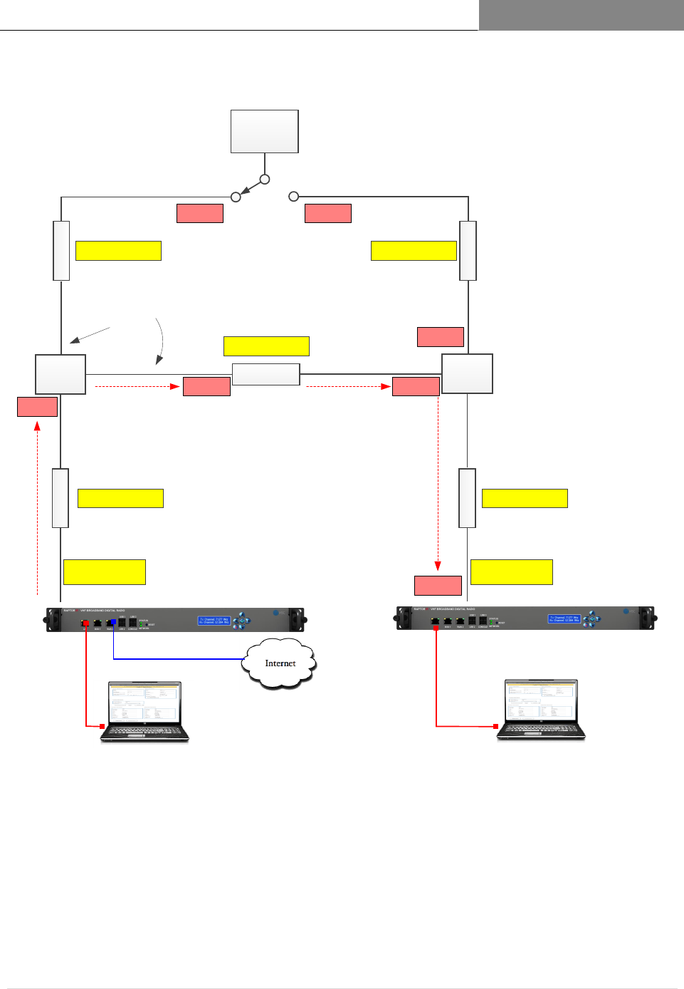
[RAPTORXR USER MANUAL VERSION 1.10]
May 2, 2017
61 | P a g e
Recommended Depot Configuration for end-to-end system testing and
6.13.2
alignment
3 dB
2-Way
Splitter
Access Registration Page via Web
Browser @ 192.168.1.1
3 dB
2-Way
Splitter
Spectrum
Analyzer
Base PC Remote PC
Data Signal
RaptorXR Base Station RaptorXR Remote Station
RF Coaxial Connections
20 dB Attenuator
Pout: 20 dBm
Rx Input: -50 dBm
Pout: 20 dBm
Rx Input: -50 dBm
20 dB Attenuator
30 dB Attenuator
3 dB Attenuator 3 dB Attenuator
0 dBm
-3 dBm -30 dBm
- 56 dBm
Access Registration Page via Web
Browser @ 192 . 168 .1.1
-23 dBm
-26 dBm-26 dBm
Figure 1.17 Recommended depot configuration for end-to-end system testing
[RAPTORXR USER MANUAL VERSION 1.10]
May 2, 2017
62 | P a g e
Common Available Channels VHF Hi-Band: 2 Channels (8,9)
6.13.3
Scrays Hill
Flintville
Available White Space Channels (shown in green) at Flintville Site
Available White Space Channels (shown in green) at Scrays Site
Figure 1.18 Common Available Channels VHF Hi-Band
Antenna Height: 95 feet
Range: 13.5 miles (21.76 km)
Tx Ant Gain: 6 dBi; Antenna Gain: 9.15 dBi
Rx Ant Gain: 9.15dBi
[RAPTORXR USER MANUAL VERSION 1.10]
May 2, 2017
63 | P a g e
Common Available Channels UHF White Space Point-to-Point Link
6.13.4
(17Channels: 13-19,25 ,32,35,44-47,51)
Oneida
Greenleaf
Available White Space Channels (shown in green) at Oneida Site
Available White Space Channels (shown in green) at Greenleaf Site
Figure 1.19 UHF White Space Point-to-Point Link
Antenna Height: 98”
Range: 17.3 miles (27.9 km)
EIRP: 36 dBm, Rx Antenna Gain: 15 dBi

[RAPTORXR USER MANUAL VERSION 1.10]
May 2, 2017
64 | P a g e
Provisioning RaptorXR Radios:
6.14
FCC-certified RaptorXR radios, as shipped, are not pre-configured to operate at any channel. The
radios per FCC, Part 15 Subpart H Rules must be successfully registered via the internet with a
certified FCC Database Provider. Metric Systems Corporation has contracted with Spectrum
Bridge.com (http://Spectrum Bridge.com/spectrum-mgmt/white-spaces/index.html )for this service.

[RAPTORXR USER MANUAL VERSION 1.10]
May 2, 2017
65 | P a g e
7 Customer Service
RMA Procedure 7.1
RETURN MATERIAL AUTHORIZATION PROCEDURE
1. To request a return material authorization (RMA) number, contact Metric Systems
Corporation at (760) 560-0348 or email us at info@metricsystems.com. When calling, please be
prepared to provide the following information:
• Your name, company, telephone and fax numbers and e-mail address;
• Part and/or model number (if applicable) of the system components to be returned;
• Reason for return and repair disposition authority.
A purchase order number will be requested at the time we issue an RMA number. Note: non-
warranty costs can be incurred through shipping damage, misuse or product misapplication. It is assumed
that the user has protected the returned component from EMI/EMP and environmental damage. The user
will be billed for items found to be defective due to the above factors.
2. Once an RMA number has been issued, ship the product to be returned to the following address:
Metric Systems Corporation
3055 Enterprise Court
Vista, CA 92081
Attn: RMA Number _______
3. For out-of-warranty repairs, you are responsible for paying all freight expense, any applicable
import and/or export duties and taxes. You are responsible for delivering the returned product
safely and undamaged to MSC.
4. On receipt of the product returned under an RMA number, an e-mail will be sent to you
confirming receipt of product and quantities received.
5. All products returned under warranty will be repaired or replaced at the sole discretion of Metric
Systems Corporation with new or equivalent materials.
[RAPTORXR USER MANUAL VERSION 1.10]
May 2, 2017
66 | P a g e
Figure 2 RMA Form
Customer Information email us at info@metricsystems.com
Bill To:
Ship To:
Company Name
Company Name
Street Address
Street Address
City, State, Zip Code
City, State, Zip Code
Contact
Contact
Phone
Phone
Fax
Fax
E-mail address
E-mail address
Purchase Order, Warranty and General Instructions
Your PO# for Repair
Authorized by (if no PO provided)
Method of Payment
Original PO number(s) under which the Unit(s)
were shipped
Service Contract if Any
Product to be repaired
Item
#
Qty
Model/Part No.
Serial Number
Symptom or Problem
1
2
3
4
Your Special Instructions
IMPORTANT NOTICE: By submitting the product described above to MSC for repair, Customer acknowledges and agrees that it shall pay the
amount charged by MSC for the repairs immediately upon receipt of written notice (or Proforma invoice) from MSC setting forth the date of
completion of repairs and the total amount due. If the amount due remains unpaid ninety (90) days after delivery of such written notice to
Customer, MSC at its option, shall have the right to retain the product or dispose of such product. MSC may retain the proceeds of any sale of
product as payment for the costs associated with the repair and disposition of the product plus reasonable costs of storing the product (“Costs”).
By submitting the product to MSC, Customer further agrees that it waives any obligation of MSC to take any actions, other than those actions set
forth herein, prior to retaining or disposing of the product. Upon the written request of Customer, MSC will submit to the Customer any amount
obtained from the disposition of the product in excess of the Costs.

[RAPTORXR USER MANUAL VERSION 1.10]
May 2, 2017
67 | P a g e
8 Technical Appendix A
RaptorXR Recommended Antenna Specification Sheets 8.1
Directional Log Period – (AUPE862)
[RAPTORXR USER MANUAL VERSION 1.10]
May 2, 2017
68 | P a g e
UFH-TV Log Period Antenna AUPE862 /Page 1 of 2
8.1.1
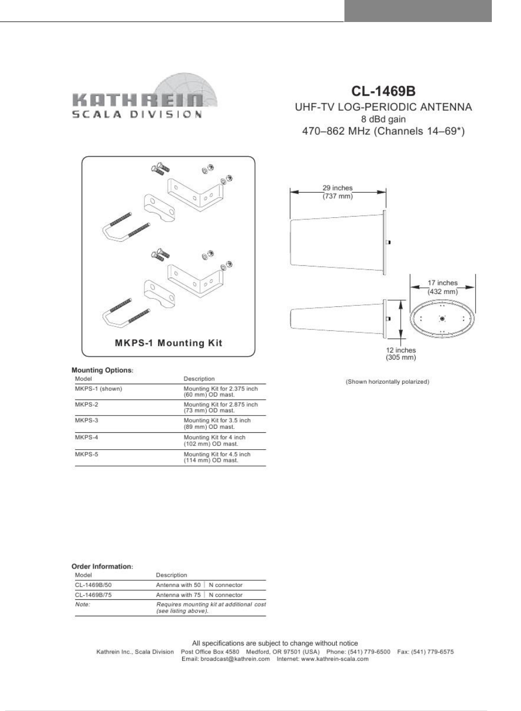
[RAPTORXR USER MANUAL VERSION 1.10]
May 2, 2017
69 | P a g e
UFH-TV Log Period Antenna AUPE862 /Page 2 of 2
[RAPTORXR USER MANUAL VERSION 1.10]
May 2, 2017
70 | P a g e
Appendix B
8.2
RaptorXR UHF Band Plan 8.2.1
RaptorXR UHF Band Plan
FCC TV White Space UHF Channels
Lower Adjacent Channel Total BW=6 MHz
Upper Adj. Channel Total BW=6 MHz
Lower Adjacent Channel (LAC)
(BW=5.9 MHz)
Lower Band
Edge (LBE)
(BW=100
KHz)
Operating
Channel
(BW=6
MHz)
Upper Band
Edge (UBE)
(BW=100
KHz)
Upper Adjacent Channel (UAC)
(BW=5.9 MHz)
Channel
Number
LAC
Start
Freq
(MHz)
LAC
Center
Freq
(MHz)
LAC
Stop
Freq
MHz
LBE Center
Frequency
(MHz)
Center
Frequency
(MHz)
UBE Center
Frequency
(MHz)
UAC
Start
Freq
MHz
UAC
Center
Freq
(MHz)
UAC
Stop
Freq
MHz
Band 1
14
464
466.95
469.9
469.95
473
476.05
476.1
479.05
482
15
470
472.95
475.9
475.95
479
482.05
482.1
485.05
488
16
476
478.95
481.9
481.95
485
488.05
488.1
491.05
494
17
482
484.95
487.9
487.95
491
494.05
494.1
497.05
500
18
488
490.95
493.9
493.95
497
500.05
500.1
503.05
506
19
494
496.95
499.9
499.95
503
506.05
506.1
509.05
512
Band 2
20
500
502.95
505.9
505.95
509
512.05
512.1
515.05
518
21
506
508.95
511.9
511.95
515
518.05
518.1
521.05
524
22
512
514.95
517.9
517.95
521
524.05
524.1
527.05
530
23
518
520.95
523.9
523.95
527
530.05
530.1
533.05
536
24
524
526.95
529.9
529.95
533
536.05
536.1
539.05
542
Band 3
25
530
532.95
535.9
535.95
539
542.05
542.1
545.05
548
26
536
538.95
541.9
541.95
545
548.05
548.1
551.05
554
27
542
544.95
547.9
547.95
551
554.05
554.1
557.05
560
28
548
550.95
553.9
553.95
557
560.05
560.1
563.05
566
29
554
556.95
559.9
559.95
563
566.05
566.1
569.05
572
Band 4
30
560
562.95
565.9
565.95
569
572.05
572.1
575.05
578
31
566
568.95
571.9
571.95
575
578.05
578.1
581.05
584
32
572
574.95
577.9
577.95
581
584.05
584.1
587.05
590
33
578
580.95
583.9
583.95
587
590.05
590.1
593.05
596
[RAPTORXR USER MANUAL VERSION 1.10]
May 2, 2017
71 | P a g e
34
584
586.95
589.9
589.95
593
596.05
596.1
599.05
602
Band Stop (Channels 35-39)
35
590
592.95
595.9
595.95
599
602.05
602.1
605.05
608
36
596
598.95
601.9
601.95
605
608.05
608.1
611.05
614
37
602
604.95
607.9
607.95
611
614.05
614.1
617.05
620
38
608
610.95
613.9
613.95
617
620.05
620.1
623.05
626
39
614
616.95
619.9
619.95
623
626.05
626.1
629.05
632
Band 5
40
620
622.95
625.9
625.95
629
632.05
632.1
635.05
638
41
626
628.95
631.9
631.95
635
638.05
638.1
641.05
644
42
632
634.95
637.9
637.95
641
644.05
644.1
647.05
650
43
638
640.95
643.9
643.95
647
650.05
650.1
653.05
656
44
644
646.95
649.9
649.95
653
656.05
656.1
659.05
662
45
650
652.95
655.9
655.95
659
662.05
662.1
665.05
668
Band 6
46
656
658.95
661.9
661.95
665
668.05
668.1
671.05
674
47
662
664.95
667.9
667.95
671
674.05
674.1
677.05
680
48
668
670.95
673.9
673.95
677
680.05
680.1
683.05
686
49
674
676.95
679.9
679.95
683
686.05
686.1
689.05
692
50
680
682.95
685.9
685.95
689
692.05
692.1
695.05
698
51
686
688.95
691.9
691.95
695
698.05
698.1
701.05
704
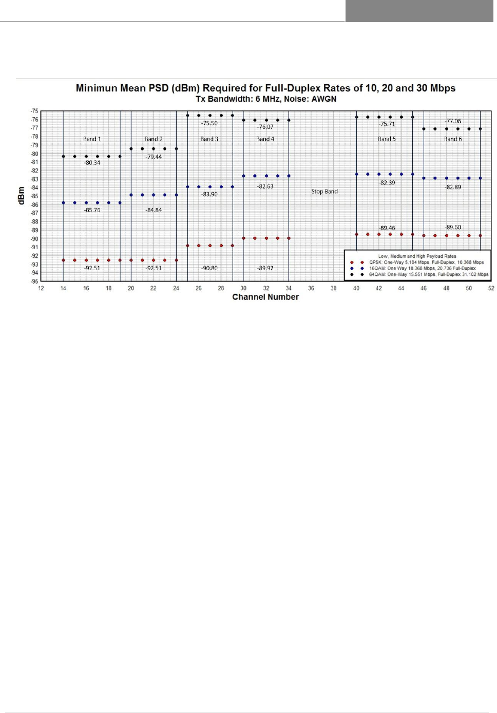
[RAPTORXR USER MANUAL VERSION 1.10]
May 2, 2017
72 | P a g e
8.2.1.1 Minimum Signal Requirements

[RAPTORXR USER MANUAL VERSION 1.10]
May 2, 2017
73 | P a g e
8.2.1.2 Technical Overview/Theory of Operation
RAPTORXR –
Broadband TVWS
Backhaul SDR Radio
System
TECHNICAL OVERVIEW
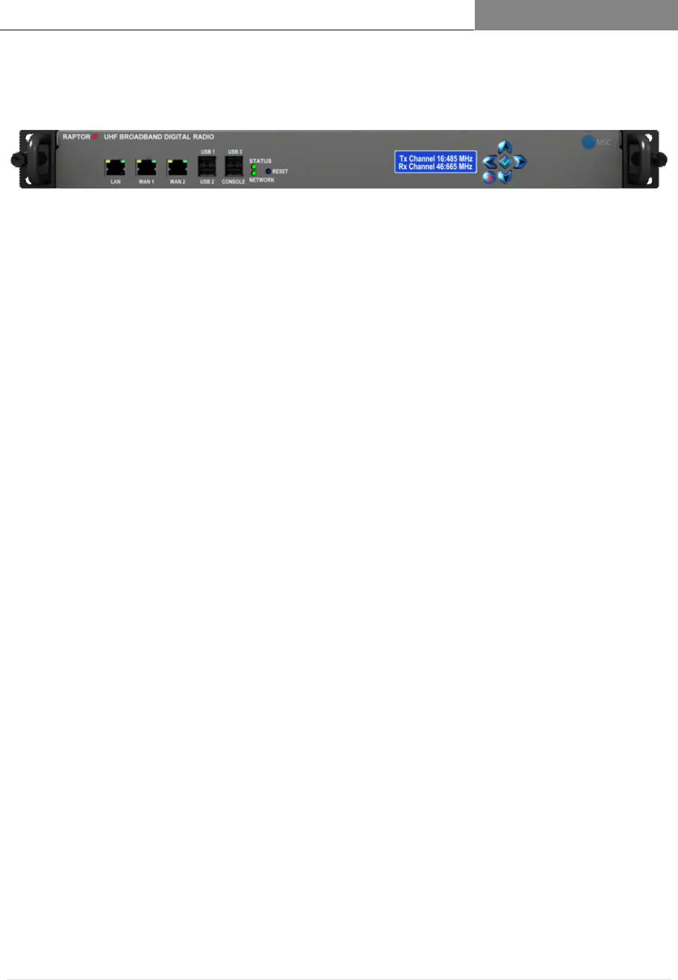
[RAPTORXR USER MANUAL VERSION 1.10]
May 2, 2017
74 | P a g e
The RaptorXR Communication Mission
The mission of the RaptorXR is to provide our customers with the ability to reliably
deliver in outdoor and indoor environments needed backhaul and edge wide -area
coverage and broadband capacity unattainable using licensed or unlicensed
microwave based systems.
This mission is accomplished via the RaptorXR, a software configurable full - duplex
digital radio system, utilizing locally available VHF/UHF TV channels called TV White
Space.
With the RaptorXR nearly any conceivable mesh network can be implemented -
ranging from basic long-range point-to-point to highly survivable back-haul
networks covering very wide service areas.
.
The RaptorXR VHF/UHF Broadband Digital Wireless System
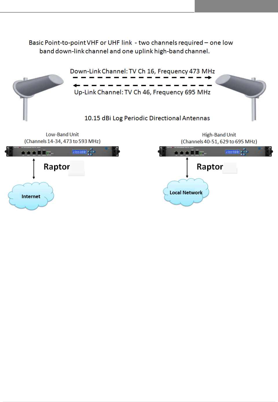
[RAPTORXR USER MANUAL VERSION 1.10]
May 2, 2017
75 | P a g e
XR XR
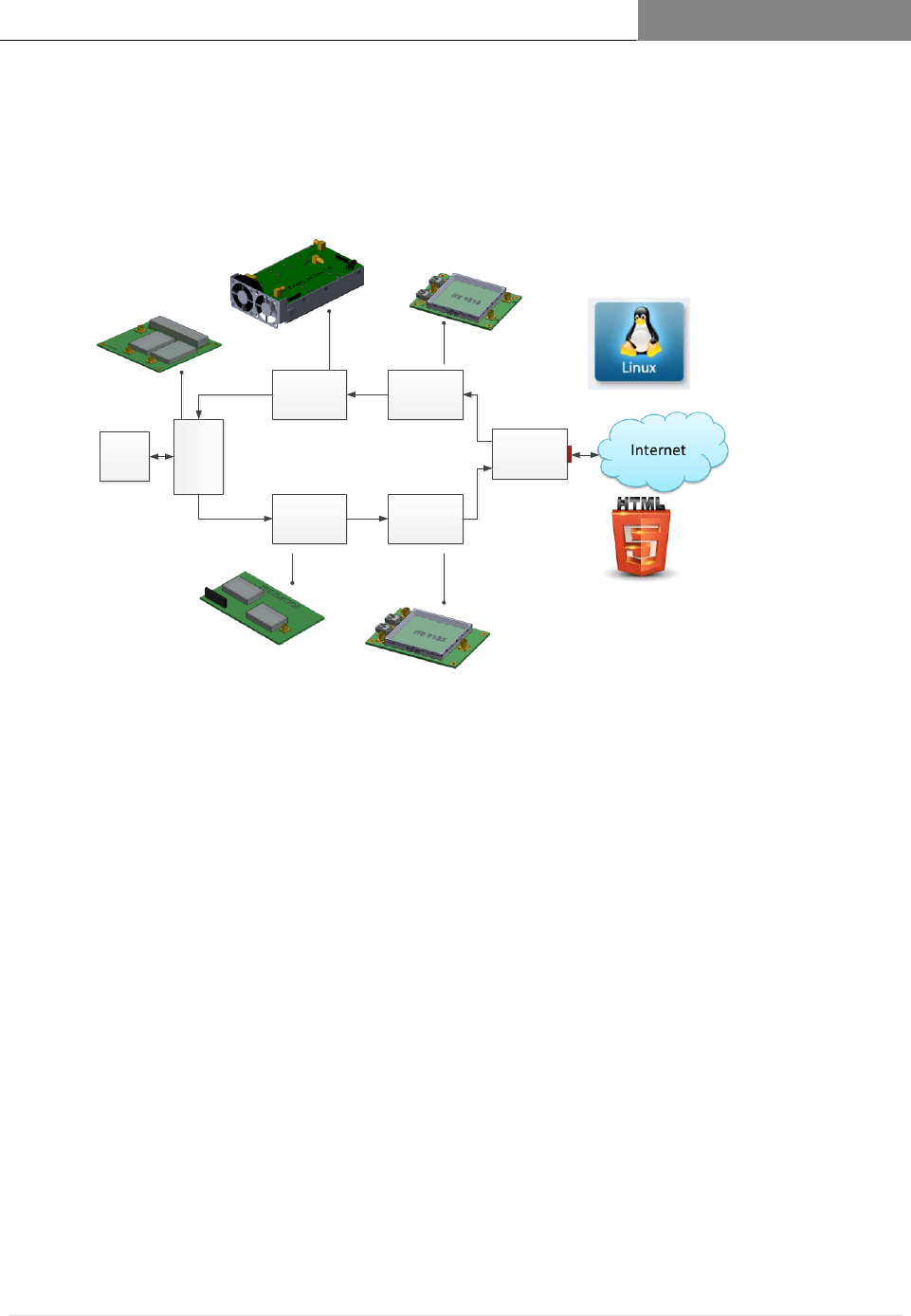
[RAPTORXR USER MANUAL VERSION 1.10]
May 2, 2017
76 | P a g e
RAPTOR TECHNOLOGY
OVERVIEW
Receiver
Pre-Selector
PA
Duplexer
Software Defined
Broadband
Digital Receiver
Software Defined
Broadband
Digital
Transmitter
Controller
Antenna
- Operating System: Debian Linux
- SDR Firmware
- Operating Process and Policy Rules
- System Administration, Control, Monitoring and Maintenace
- Network Topology – Software Defined Networking (SDN)
- Spectrum Management Process and Policy
- Database Operational Interface
- Equipment Set-up and Configuration
- Wide-area Network Configuration
Enables simultaneous
transmit and receive
operation
Ultra-Linear amplifier amplifies the low
level wave form signals prior to
transmission
Broadband waveform generator -
creates the waveforms that convey
internet information
ethernet
Filters and amplifies the weak
incoming signal from the remote
Raptor.
Broadband waveform
receiver detects and
processes the incoming
digital waveform.
All Raptors –Base
Stations and
Subscriber
Stations follow
the same
architecture.
Software radio
components
driven by an open
systems OS
followed by wide
band amplifiers.
This architecture
enables reusable
software and
common parts
leading to a
consistent
manufacturing
process.
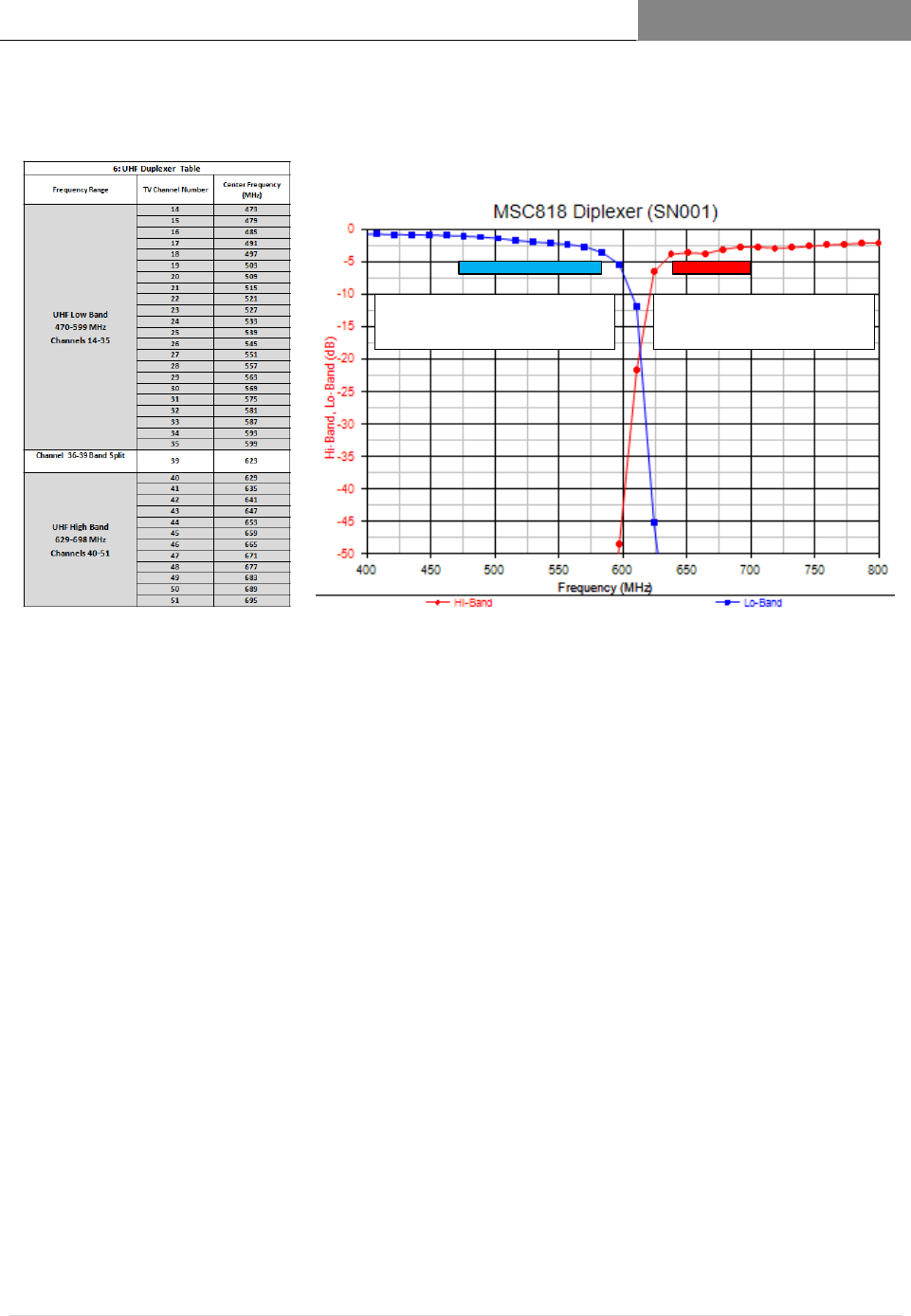
[RAPTORXR USER MANUAL VERSION 1.10]
May 2, 2017
77 | P a g e
RaptorXR Diplexer Performance (400 –800 MHz)
Down-link Channels: 14
(470 MHz) to 35 (599 MHz)
Up-link Channels: 40 (626
MHz) to 51 (698 MHz)
RaptorXR Point-to-Point Bandplan and Duplexer Response
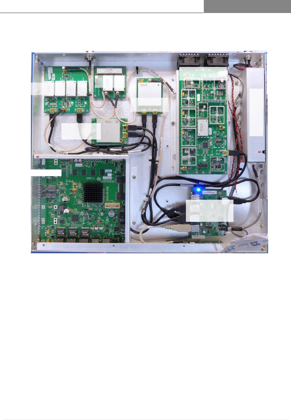
[RAPTORXR USER MANUAL VERSION 1.10]
May 2, 2017
78 | P a g e
RaptorXR Internal Sub-Systems
Processor
Rx Pre-Selector
High or Low Band
Rx
Demodulator
Tx Modulator
UHF
Duplexer
Ultra-Linear PA
Power Supply
28 VDC DC Power Input
Antenna Port
Internal
Communications
Hub
Front Panel Display
END