MHOUSE SRL 433TX4 Handheld Transmitter User Manual IST WG20 GB 4865 Rev01
MHOUSE SRL Handheld Transmitter IST WG20 GB 4865 Rev01
UserManual.wiki
>
MHOUSE SRL
>
433TX4 User Manual
>
User Manual
Contents
1.
Flyer
2.
User Manual
User Manual
Navigation menu
Upload a User Manual
Namespaces
Wiki Guide
HTML
PDF
Info
Views
User Manual
Discussion / Help
Navigation


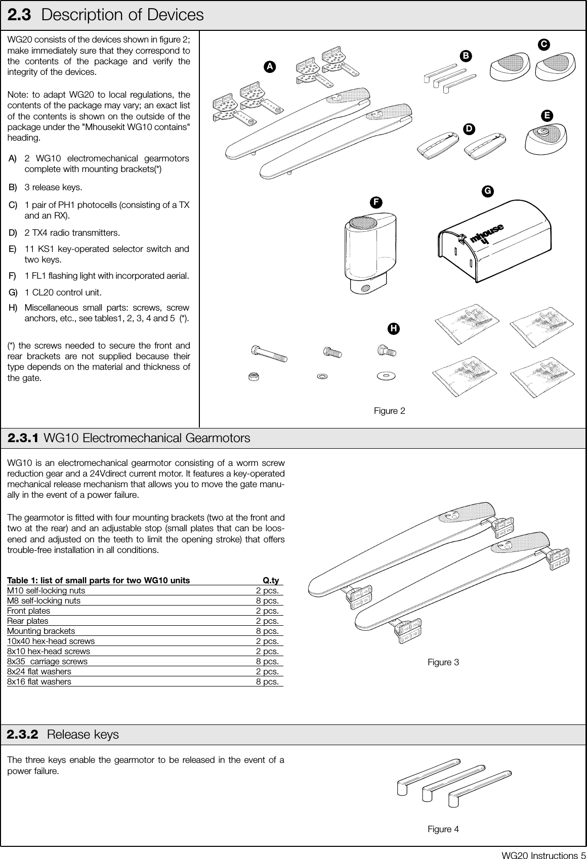
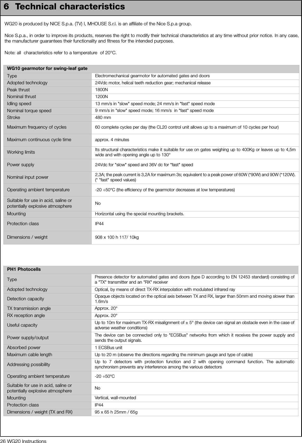
![6 WG20 Instructions2.3.3 CL20 Control Unit2.3.4 PH1 PhotocellsThe CL20 unit actuates the gearmotors and provides for the control andsupply of the different components; it features an electronic board withincorporated radio receiver; a housing [B] for the PR1 buffer battery(optional), which is necessary for operation in case of power failure.The CL20 control unit can actuate the gearmotors with two speeds:"slow" and "fast".The three P1, P2 and P3 buttons [C] and the corresponding LED's areused to program the control unit.To facilitate the electrical connections there are separate terminals foreach device [A], which are removable and colour-coded based on thefunction performed. Next to each input terminal there is a LED that sig-nals its status.The connection to the power supply is very easy: just insert the plug in apower outlet.Table 2: List of small parts for CL20 Q.ty4.2X32 self-tapping screw 4 pcs.s 6 c nylon screw anchor 4 pcs.Figure 5ABCThe pair of PH1 wall-mounted photocells, once they are connected tothe control unit, enable the detection of obstacles found on the opticalaxis between the transmitter (TX) and the receiver (RX).Table 3: List of small parts for PH1 Q.ty3.5X25 self-tapping screw 4 pcs.4.2X32 self-tapping screw 4 pcs.s 5 c nylon screw anchor 4 pcs.2.3.5 KS1 Key-Operated Selector SwitchThe KS1 key-operated two-position selector switch enables gatecontrol without using the radio transmitter. It is equipped with internallight for locating in the dark.There are two commands, which depend on the direction of rotation ofthe key: "OPEN" and "STOP"; then the key, which is spring loaded,returns to the centre position.Figure 7Table 4: List of small parts for KS1 Q.tyHI LO 4X9.5 screw 2 pcs.3.5X25 self-tapping screw 4 pcs.s 5 c nylon screw anchor 4 pcs.2.3.6 FL1 Flashing Light with Incorporated AerialTable 5: List of small parts for FL1 Q.ty4.2X32 self-tapping screw 4 pcs.s 6 c nylon screw anchor 4 pcs.The flashing light is controlled by the CL20 control unit and signalsdanger when the gate is moving. Inside the flashing light there is alsothe aerial for the radio receiver.Figure 82.3.7 TX4 Radio TransmittersThe radio transmitters are used for the remote control of the gateopening and closing manoeuvres. They feature four buttons that can allbe used for the 4 types of command to a single automation unit, or tocontrol up to 4 different automation units.The transmission of the command is confirmed by the LED [A]; an eyelet[B] allows them to be hung on a keyring. Figure 9ABFigure 6](https://usermanual.wiki/MHOUSE-SRL/433TX4.User-Manual/User-Guide-606889-Page-6.png)
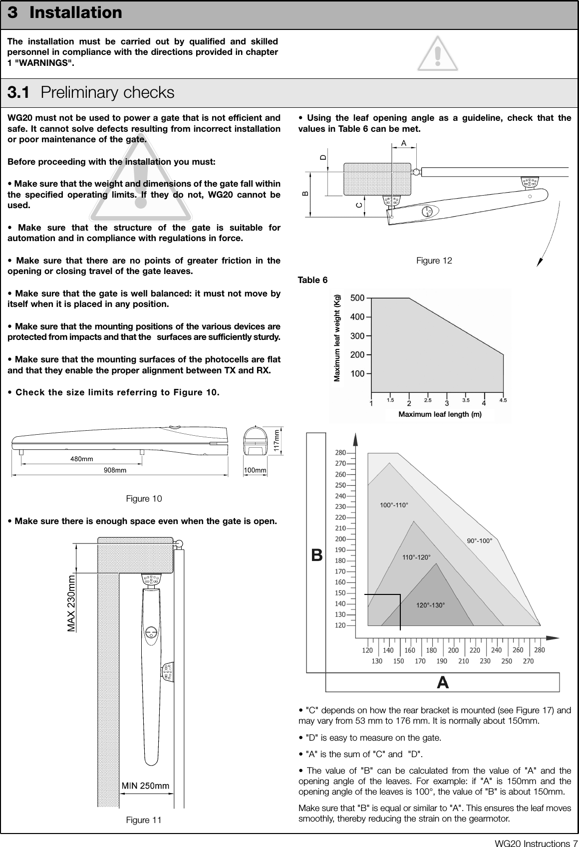
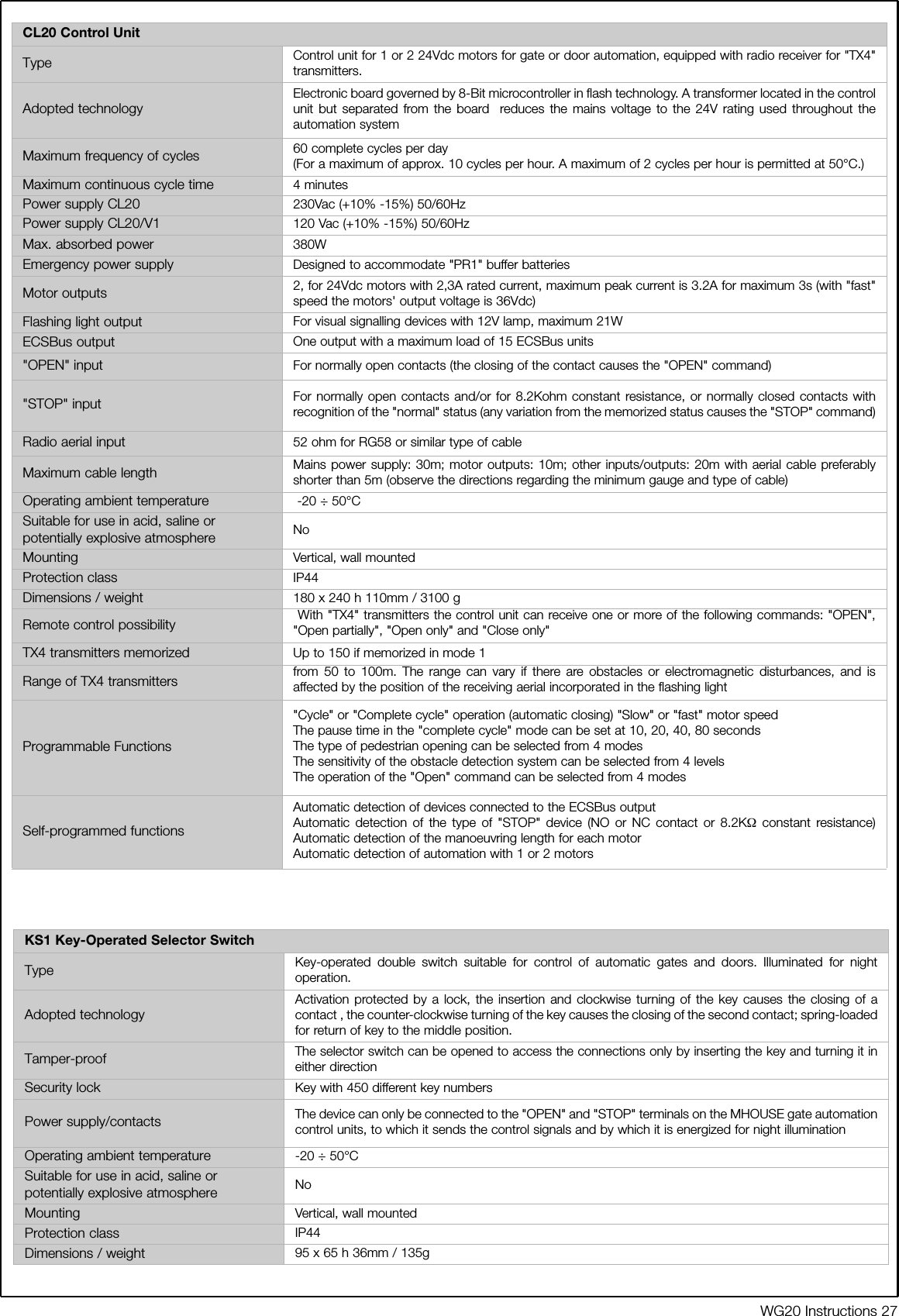
![8 WG20 Instructions3.1.1 Operating LimitsChapter 6 "Technical Characteristics" provides the fundamental dataneeded to determine whether all the WG20 components are suitable forthe intended application.In general, WG20 is suitable for the automation of gates featuring leavesup to 4,5m wide, weighing up to 400 kg, with opening angle of up to130° for residential applications.The shape of the gate and the climatic conditions (e.g. presence ofstrong wind) may reduce these maximum limits. In this case it isnecessary to measure the torque needed to move the leaves under theworst conditions, and to compare it to the data provided in the technicalcharacteristics chart for the WG20 gearmotor.3.1.2 Tools and MaterialsMake sure you have all the tools and materials needed to installthe system; make sure that they are in good condition andserviceable according to current safety standards. See examplesin Figure 13.3.1.3 List of CablesThe cables required for the installation of WG20 may vary depending on the type and quantity of devices to be installed; figure 14 shows the cablesneeded for a typical installation; no cable is supplied with WG20.Table 7: list of cablesConnection Cable type Maximum length allowed[A] Power supply line 3x1.5mm2cable 30m (note 1)[B] FLASH light output 2x0,5mm2cable 20m[C] Radio aerial RG58 type shielded cable 20m (recommended less than 5m)[D] ECSBus input/output 2x0,5mm2cable 20m (note 2)[E] STOP input 2x0,5mm2cable 20m (note 2)[F] OPEN input 2x0,5mm2cable 20m (note 2)[G] M1 and M2 motors output 3x1mm2cable 10mWARNING: the cables used must be suitable for the type of installation; for example, an H03VV-F type cable is recommended for indoorapplications, while H07RN-F is suitable for outdoor applications.Note 1 A power supply cable longer than 30 m may be used provided it has a larger gauge, e.g. 3x2.5mm2, and that a safety grounding systemis provided near the automation unit.Note 2 For the ESCbus, STOP and OPEN cables, there are no special contraindications to the use of a single cable that groups together multipleconnections; for example, the STOP and OPEN inputs can be connected to the KS1 selector switch using a single 4x0,5mm2cable.Figure 13B C DA EDDGGFFigure 14](https://usermanual.wiki/MHOUSE-SRL/433TX4.User-Manual/User-Guide-606889-Page-8.png)
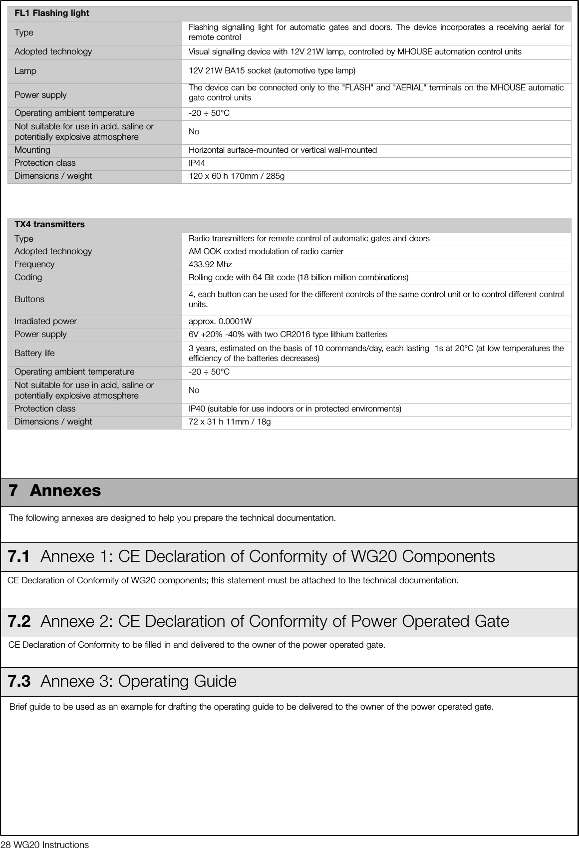
![1 Choose the mounting position in accordance with the specifications inparagraph 3.1 "Preliminary Checks".2 Check that the mounting surface is perfectly smooth, vertical andsufficiently compact. WG10 does not come with a mounting system,consequently one will have to be chosen according to the surfacematerial.3 Lay the conduit for the power cable.4 To obtain the rear supports, assemble two brackets and the rear plateas shown in Figure 16.5 To obtain different "C" values (see Figure 12) assemble the brackets andplate as shown in Figure 17.6 To obtain the front support, assemble two brackets and the front plateas shown in Figure 18.7 Remove the back cover of the gearmotors by sliding it in the directionof the arrows.8 Move the leaves to the "gate closed" position.9 Referring to the "B" distance calculated from Table 6, place the rearsupport in the correct position on the mounting surface, Check that thereis a suitable surface at the values in Figure 22, i.e. where the frontsupport is mounted.10 Mark the drill points for the rear support using the support itself as areference point. Drill holes in the mounting surface for 4 anchors [A] witha diameter of at least 8 mm (not included in supply). Fix the plate withsuitable screws [C] and washers [B].WG20 Instructions 9With the exception of the power line that supplies the control unit, therest of the system uses extra-low voltage (approx. 24V); the wiring cantherefore be done by personnel that is not properly qualified, providedthat all the instructions in this manual are carefully observed.After selecting the position of the various devices (refer to figure 1) youcan start preparing the conduits for the electrical cables connecting thedevices to the control unit. The conduits are designed to protect the electrical cables and preventaccidental breakage, which may be caused by the passage of vehicles,for instance.3.2 Preparing the Electrical SystemAlthough the connection of WG20 to the electrical mains is beyond thescope of this manual, we wish to remind you that:• The power supply line must be laid and connected by a qualifiedprofessional electrician.• Alternatively, have a suitably protected 16A "shuko" outletinstalled, where you can plug in WG20.• The electric line must be grounded and protected against shortcircuits; a bipolar disconnection device must also be present withcontact separation of at least 3 mm, which allows the power sup-ply to be disconnected during the installation and maintenance ofthe WG20.3.2.1 Connection to the Electrical Mains3.3 Installation of the Various Devices3.3.1 WG10 gearmotor mountingFigure 15Figure 16Figure 18Figure 19Figure 17 Figure 20ABC](https://usermanual.wiki/MHOUSE-SRL/433TX4.User-Manual/User-Guide-606889-Page-9.png)
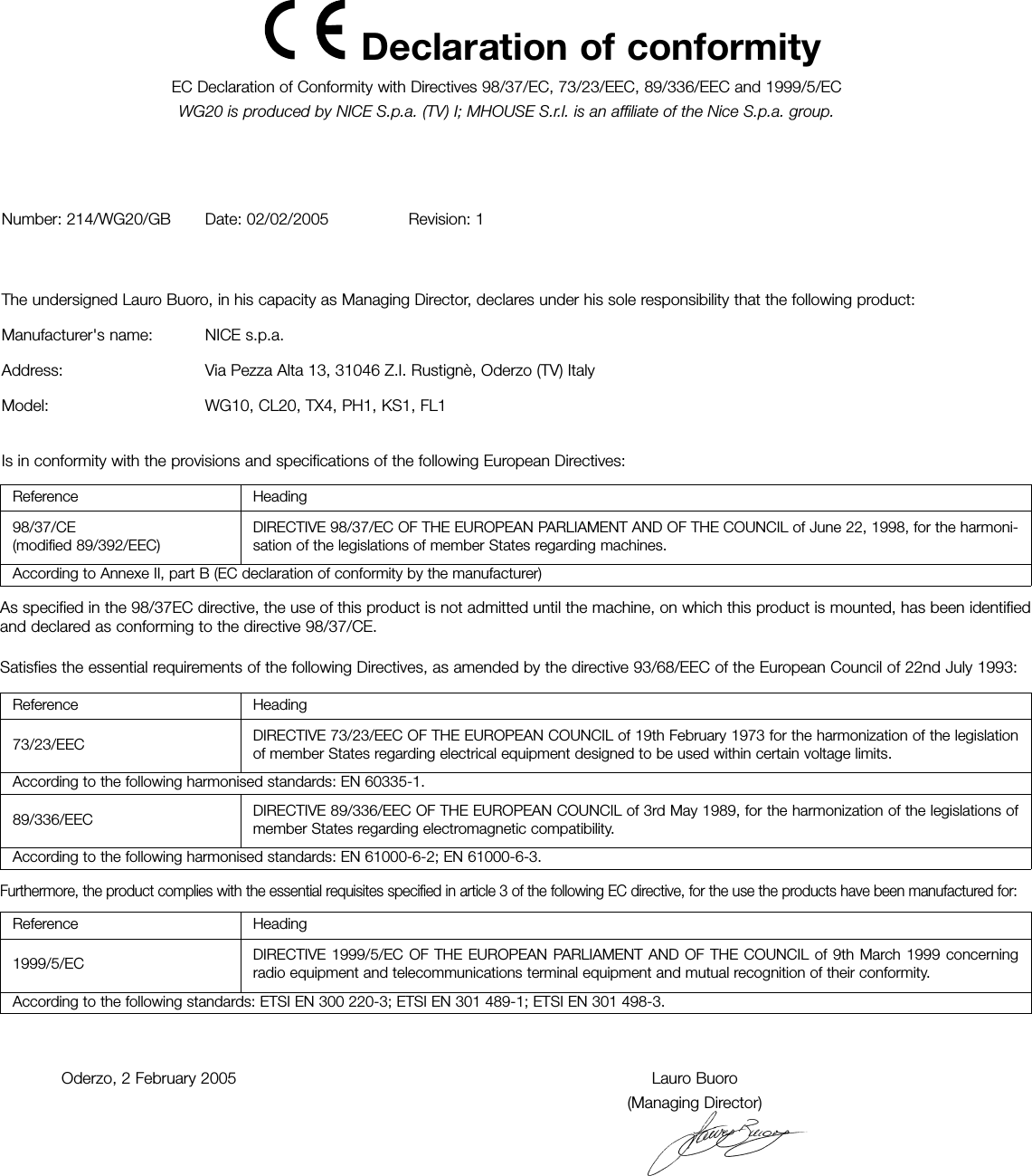
![11 Check that the plate is perfectly level, the slots on the bracket allowsmall differences in alignment to be corrected.12 Referring to Figure 22, place the front support at a distance of 820mm from the rear support and 38 mm lower.13 Temporarily fix the front support to the leaf with a clamp.14 Lift up the gearmotor and fit the fork into the hole in the front support. 15 Keep the gearmotor lifted and pull it to open the gate until the hole inthe plate matches the hole in the gearmotor. Fix the gearmotor to therear support [E] with the screw [D], nut [G] and washer [F].16 Firmly tighten the nut and then loosen it by about half a turn in orderto allow the gearmotor to rotate on the support.17 Fix the gearmotor to the front support and anchor it with the screw [I]and washer [H]. Fully tighten the screw.18 Release the gearmotors using the appropriate release keys (see the"Gearmotor Release" paragraph on page 34).19 Test the mechanism by moving the gate by hand. Check that the forkslides perfectly on the worm screw of the gear motor and that thereremains a margin of at least 5 mm from the opening and closing stops,making sure, however, that not too much of the worm screw remainsunused.20 If necessary, test the other assembly positions allowed by the frontand rear plates. See Figure 17.21 If necessary, adjust the stops by loosening them with Allen keys [N]and moving them to the required position. The opening stop [L] is usedif there are no opening stops on the ground. Normally, the leaves stopagainst the closing stop during the closing manoeuvre. After adjustingthe stops, fully tighten the screws.22 Secure the front support permanently using screws suited to thematerial of which the gate is constructed. 23 Fix the gearmotor once more using the appropriate release keys (seethe "Gearmotor release" paragraph on page 34).24 Thread the electrical cable through the conduit and bring it to thecontrol unit.N.B.: the cable leaving the gear motor must be curved so that it canfollow the gearmotor when it rotates to open and close the leaf.Figure 21Figure 23Figure 24Figure 25Figure 26Figure 22Figure 2710 WG20 InstructionsDEFGHINL](https://usermanual.wiki/MHOUSE-SRL/433TX4.User-Manual/User-Guide-606889-Page-10.png)
![WG20 Instructions 111 Select the position of the two elements that make up the photocell (TXand RX) observing the following directions:• Position them at a height of 40-60 cm from the ground, on bothsides of the area to be protected, on the street side of the installation andas close as possible to the edge of the gate, no farther than 15 cm.• Point transmitter TX towards receiver RX, with a maximum toleranceof 5°. • In the selected locations there must be a conduit for threading the cables.2 Remove the front glass [A] by prising it out with a slotted tipscrewdriver applied to the bottom.3 Press the lens in order to separate the two shells.4 Breach two of the four holes [B] at the bottom with a screwdriver.5 Position the photocell at the point where the conduit arrives; the holeat the bottom [D] should match the point where the cables come out ofthe wall; mark the drilling points using the bottom as reference.6 Drill the holes in the wall using a hammer drill with a 5 mm bit and insertthe 5 mm screw anchors.7 Secure the bottom with the screws [C].8 Connect the electric cable to the appropriate TX and RX terminals.From an electrical viewpoint, TX and RX must be connected in parallel asshown in Figure 33. It is not necessary to observe any polarity. Theterminals can be removed in order to facilitate the operations; make theconnections and then reinsert them.9 Secure the cover shell [E] using the two screws [F] and a Phillipsscrewdriver. Then insert the glass [G], pressing it gently to close it.25 Loosen the cable gland under the gearmotor, push the power cablethrough and then firmly close the cable gland.26 Make electrical connections as follows. 27 Close the back cover of the gearmotors by inserting it in the directionof the arrows.Figure 283.3.2 PhotocellsAFigure 29Figure 30Figure 31Figure 32Figure 33Figure 34BCDCEFGTX RXbrownblueyellow-green](https://usermanual.wiki/MHOUSE-SRL/433TX4.User-Manual/User-Guide-606889-Page-11.png)
![12 WG20 Instructions1 Determine the position of the flashing light: it should be near the gateand easy to see; it can be secured to a horizontal as well as verticalsurface.2 Slide out the diffuser [A] from the bottom by pressing the two buttons[B].3 Separate the lamp holder with the aerial from the base.4 Breach the four holes for the screws and the hole for the passage ofthe cables in the bottom or side, depending on the installation position,using a screwdriver. 5 Mark the drilling points using the bottom as reference and make surethat the hole in the bottom matches the outlet for the cables.6 Drill the holes in the wall using a hammer drill with a 6 mm bit and insertthe 6 mm screw anchors1 Determine the position of the selector switch; it must be installedoutdoors, alongside the gate and at a height of approx. 80 cm, so thatit can be used by people of different height.2 Remove the front glass [A] by prising it out with a slotted tipscrewdriver applied to the bottom.3 To separate the bottom from the shell you need to insert the key and keep itturned, then pull with a finger inserted in the hole for the passage of the cables.4 Breach the four holes at the bottom with a screwdriver; mark thedrilling points using the bottom as reference; make sure that the hole inthe bottom matches the outlet for the cables.5 Drill the holes in the wall using a hammer drill with a 5 mm bit and insertthe 5 mm screw anchors6 Secure the bottom using the four screws [B].7 Connect the electric cables to the appropriate OPEN and STOPterminals, as shown in figure 38. It is not necessary to observe anypolarity. The terminals can be removed in order to facilitate theoperations; make the connections and then reinsert them. 8 To insert the shell on the bottom you need to turn the key. After youhave inserted it, turn the key back to the centre position.9 Secure the body [C] using the two screws [D] and a Phillipsscrewdriver. Finally insert the glass [E], pressing it gently to close it.3.3.3 KS1 Key-Operated Selector SwitchFigure 35Figure 36Figure 37Figure 383.3.4 FLI Flashing LightFigure 39ABEDCFigure 40Figure 41AB](https://usermanual.wiki/MHOUSE-SRL/433TX4.User-Manual/User-Guide-606889-Page-12.png)
![WG20 Instructions 137 Secure the bottom with the screws [C].8 Connect the electrical cables to the appropriate FLASH and "aerial"terminals as shown in figure 43. You do not need to observe any polarityon the FLASH terminal; however, for the connection of the shielded cableto the aerial, connect the braid as shown in figure 44. The terminals canbe removed in order to facilitate the operations; make the connectionsand then reinsert them.9 Fit the lamp holder on the base and press it down until it snaps intoposition.10 Slide in the diffuser, pressing the buttons and fitting it on the bottom.Rotate it in the desired direction then press it down until the two buttonssnap into their seat.Figure 42Figure 45CC3.3.5 CL20 Control Unit1 Select the installation position in a location protected from possibleimpacts and near the gate so that the length of the cables can bereduced.2 Remove the cover by prising it open with a screwdriver applied to thebottom opening, slide it out a few centimetres and then lift it from thebottom .3 Arrange the conduit for the electric cables so that they can be let inthrough the bottom of the control unit as shown in figure 47.4 Drill a hole through the bottom of the control unit and use suitableunions to fasten the conduits for the electric cables.5 Breach the two bottom holes using a screwdriver, then mark the drillingpoints using the bottom as reference.6 Drill the holes in the wall using a hammer drill with a 6 mm bit and insertthe 6 mm screw anchors7 Secure the bottom with the appropriate screws [A].Figure 46Figure 47Figure 48AFigure 43 Figure 44](https://usermanual.wiki/MHOUSE-SRL/433TX4.User-Manual/User-Guide-606889-Page-13.png)
![14 WG20 Instructions8 Refer to figure 49 for the electrical extra low voltage connection of thevarious devices to the CL20 control unit terminals.• The terminals have the same colour coding as the correspondingdevices; for example, the grey terminal (OPEN) of the KS1 selectorswitch must be connected to the grey terminal (OPEN) of the controlunit.• For most connections you do not need to observe any polarity; onlyfor the shielded cable of the aerial it is necessary to connect the centralcore and the shield as shown in detail [B]. The cable for the motors mustbe connected as shown in detail [A].• Keep in mind that, to prevent the jamming of the two leaves, thecontrol unit commands the M2 motor to open first, followed by M1 (vice-versa for the closing manoeuvre). Therefore make sure that the motorthat drives the leaf that strikes the mechanical stop is connected toterminal M1 (outer one), while the motor that drives the other leaf mustbe connected to terminal M2.• If only one motor is used (single-leaf gate) it must be connected toterminal M2 while terminal M1 remains free.FL1PH1 PH1 KS1WG10M2WG10M1To facilitate the installation operations, the terminals [B] can be removedas shown in figure 49; make the connections and then re-insert them.When you have completed the connections, use clamps to secure thecables to the appropriate fasteners [C].9 To close the control unit you need to rest the cover on the bottomapproximately 3 cm above the final position, then press it down until itsnaps into place.CBFigure 50Figure 51Figure 49brownyellow/green bluebrownyellow/green blueAB](https://usermanual.wiki/MHOUSE-SRL/433TX4.User-Manual/User-Guide-606889-Page-14.png)
![WG20 Instructions 153.4 Power Supply Connection3.5 Initial checksThe connection of the CL20 control unit to the mains must bemade by a qualified electrician.To carry out tests, insert the plug for CL20 in a power outlet; if neces-sary, use an extension cord.The CL20 control unit must be permanently connected to the mainspower supply for the testing and commissioning operations. This operation must be performed as follows by a qualified electrician:1 Make sure that the plug of the CL20 control unit is not plugged into thepower socket2 Disconnect the power cable from the CL20 control unit power supplyterminal 3 Slacken the collar close to the terminal and remove the cable4 Insert the final power supply cable of the control unit through the collar5 Connect the cable to the terminal of the control unit6 Tighten the collar Figure 52As soon as the CL20 control unit is energized, you should check thefollowing:1 Make sure that the "ECSBus" LED [A] flashes regularly, with about oneflash per second.2 Make sure that the SAFE LED [B] on the photocells flashes (both on TXand RX); the type of flashing is not important as it depends on other factors;what is important is that the LED should not be steadily on or steadily off.3 Make sure that the night light [C] on the KS1 key-operated selectorswitch is on.4 If the above conditions are not satisfied, you should immediately switchoff the power supply to the CL20 control unit and check the cableconnections more carefully. For more useful information see alsochapters 5.5 "Troubleshooting" and 5.6 "Diagnostics and Signals".Figure 55Figure 54BC3.5.1 Recognition of Connected DevicesWhen you have completed the initial checks, the control unit mustrecognize the devices connected to it on the "ECSBus" and "STOP"terminals.1 On the control unit, press the P2 button [C] and hold it down for atleast three seconds, then release the button.2 Wait a few seconds for the control unit to finish recognizing thedevices.3 When the learning procedure is completed, the STOP LED [A] mustremain on, while the P2 LED [B] must go off. If the P2 LED flashes itmeans that an error has occurred: see paragraph 5.5 "Troubleshooting".The connected devices recognition stage can be repeated again at anytime, even after the installation (for example, if an additional photocell isinstalled); just repeat the procedure starting from step 1. Figure 56BACAFigure 53](https://usermanual.wiki/MHOUSE-SRL/433TX4.User-Manual/User-Guide-606889-Page-15.png)
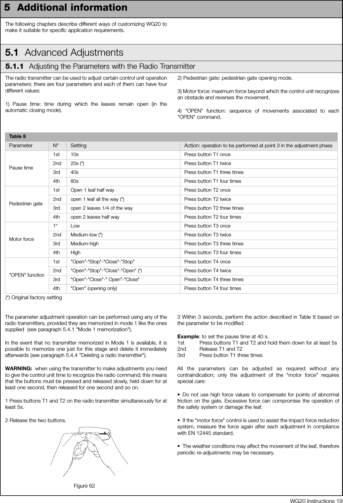
![16 WG20 Instructions3.5.3 Checking the Radio TransmittersAfter recognizing the devices, the control unit must learn to recognize theleaves' opening and closing angles .During this stage, the leaves' opening angle is measured from theclosing mechanical stop to the opening mechanical stop.Fixed and sufficiently sturdy mechanical stops are required.1 Release the motors using the appropriate keys (see the "GearmotorRelease" paragraph on page 34) and move the leaves to mid travel sothat they are free to move in both opening and closing directions; thenlock the motors.2 On the control unit press the P3 button [B] and hold it down for at leastthree seconds, then release the button.Wait for the control unit to complete the recognition stage: closing of theM1 motor to the mechanical stop, closing of the M2 motor to themechanical stop, opening of the M2 and M1 motors to the openingmechanical stop; complete closing of M1 and M2.• If the first manoeuvre of one or both leaves is not to close, press P3to interrupt the recognition stage, then switch the polarity of the motor/sthat opened by exchanging the two brown and blue wires on theterminal.• If the first motor to move in the closing direction is not M1, press P3to interrupt the recognition stage, then switch the motor connections onthe terminals.• If any device is triggered during the recognition stage (photocells, key-operated selector switch, pressure on P3, etc.), the recognition stage willimmediately be interrupted. It will therefore be necessary to start againfrom the beginning.3 If at the conclusion of the search the P3 LED [A] flashes, it means thatan error has occurred; see paragraph 5.5 "Troubleshooting".The opening angles recognition stage can be repeated again at any time,even after the installation (for example, if one of the opening stops ismoved); just repeat the procedure starting from step 1. 3.5.2 Recognition of Gate Leaves' Opening and Closing AnglesFigure 57BATo check the transmitters just press one of the four buttons, make surethat the red LED flashes and that the automation executes thecommand.The command associated to each button depends on how they havebeen memorized (see paragraph 5.4 "Memorization of RadioTransmitters"). The transmitters supplied have already been memorizedand when you press the buttons the following commands aretransmitted:Button T1 "OPEN" commandButton T2 "Open pedestrian gate" commandButton T3 "Open only" commandButton T4 "Close only" command3.6 Regulations3.6.1 Selecting the Speed of the LeafThe leaves can be opened and closed at two speeds: "slow" or "fast".To switch from one speed to the other press the P2 button [B]momentarily; the corresponding P2 LED [A] will light up or go off; if theLED is off the speed is "slow", if the LED is on the speed is "fast".Figure 59BAT1T2T3T4Figure 58](https://usermanual.wiki/MHOUSE-SRL/433TX4.User-Manual/User-Guide-606889-Page-16.png)
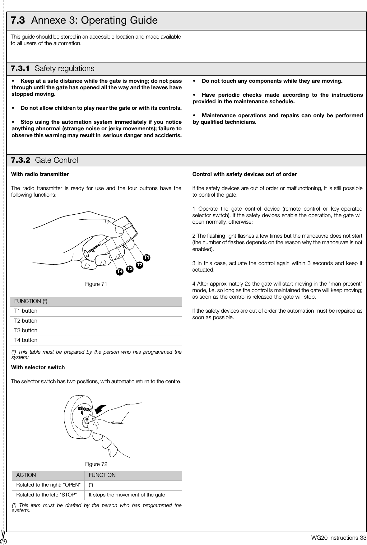
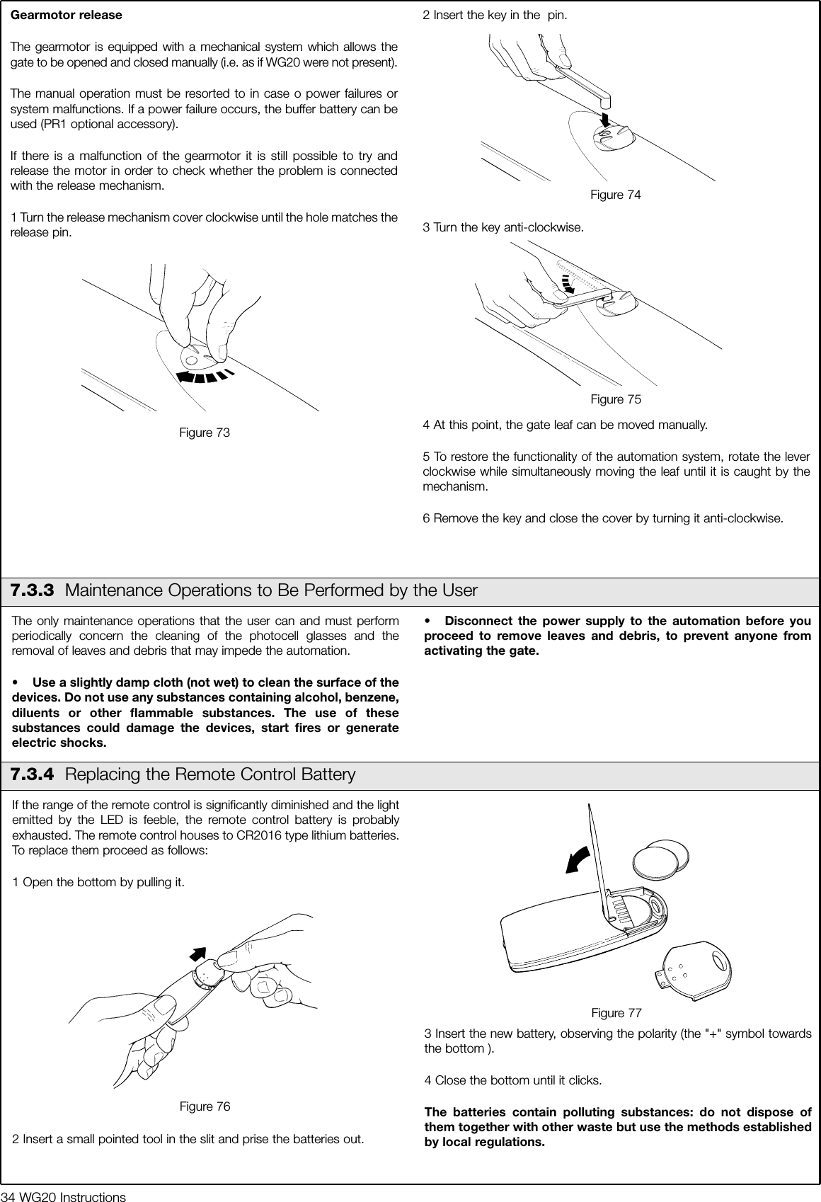
![Istructions WG20 171 Make sure that the provisions contained in chapter 1"WARNINGS" have been carefully observed.2 Using the selector switch or the radio transmitter, test the opening andclosing of the gate and make sure that the leaves move in the intendeddirection.The test should be carried out a number of times to make sure that thegate moves smoothly, that there are no points of excessive friction andthat there are no defects in the assembly or adjustments.3 Check the proper operation of all the safety devices, one by one(photocells, sensitive edges, etc.). In particular, each time a device isactivated the "ECSBus" LED on the control unit flashes for a longer time,confirming that the control unit recognizes the event.4 To check the photocells and make sure that there is no interferencewith other devices, pass a 5 cm diameter, 30 cm long cylinder on theoptical axis, first near TX, then near RX and finally at the mid-pointbetween them and make sure that in all these cases the device istriggered, switching from the active to the alarm status and vice-versa;finally, that it causes the intended action in the control unit, for examplethat it causes the reversal of the movement during the closingmanoeuvre.5 Measure the impact force according to EN 12445 standard. If "motorforce" control is used to assist the system for the reduction of the impactforce, try to find the adjustment that gives the best results.3.6.2 Selecting the Type of Operating CycleThe opening and closing of the gate can take place according to differentoperating cycles:• Single cycle (semiautomatic): the gate opens with a command andstays open until the next command is given, causing it to close.• Complete cycle (automatic closing): the gate opens with a commandand then closes automatically after a short time (for the time, seeparagraph 5.1.1 "Adjusting the Parameters with the Radio Transmitter").To switch from one operating cycle to the other, press the P3 button [B]momentarily; the corresponding LED [A] will light up or go off; if the LEDis off the cycle is "single", if the LED is on the cycle is "complete".Figure 60BA3.7 Testing and commissioningThese are the most important operations, designed to guarantee themaximum safety and reliability of the automation system.The testing procedure can also be used as a periodic check of thedevices that make up the automation.The testing and commissioning operations must be performed byqualified and experienced personnel who must establish whattests should be conducted based on the risks involved, and verifythe compliance of the system with applicable regulations,legislation and standards, in particular with all the provisions ofEN 12445 standard which establishes the test methods for gateautomation systems.3.7.1 Testing3.7.2 CommissioningFigure 61The commissioning operations can be performed only after allthe tests have been successfully carried out. Partialcommissioning or implementation of "temporary" conditions arenot permitted.1 Prepare the technical documentation for the automation, which mustinclude at least: assembly drawing (e.g. figure 1), wiring diagram (e.g.figure 14), analysis of hazards and solutions adopted, manufacturer'sdeclaration of conformity of all the devices installed. For WG20 useAnnexe 1 "EC Declaration of Conformity of the WG20 components".2 Post a label on the gate providing at least the following data: type ofautomation, name and address of manufacturer (person responsible forthe "commissioning"), serial number, year of manufacture and "CE"marking.3 Fill out the declaration of conformity and deliver it to the owner of theautomation system; for this purpose you can use Annexe 2 "ECDeclaration of Conformity".4 Prepare the operating guide and deliver it to the owner of theautomation system; Annexe 3 "OPERATING GUIDE" can be used as anexample.5 Prepare the maintenance schedule and deliver it to the owner of theautomation system; it must provide directions regarding themaintenance of all the automation devices.6 Before commissioning the automation system inform the ownerregarding dangers and hazards that are still existing.](https://usermanual.wiki/MHOUSE-SRL/433TX4.User-Manual/User-Guide-606889-Page-17.png)
![WG20 Instructions 21Normally the recognition of the devices connected to the ECSBus andthe STOP input takes place during the installation stage. However, if newdevices are added or old ones removed, the learning process can begone through again by proceeding as follows:1 On the control unit, press the P2 [B] button and hold it down for at leastthree seconds, then release it.2 Wait a few seconds for the control unit to finish recognizing thedevices.3 When the recognition stage is completed the P2 LED [A] should go off.If the P2 LED flashes it means that something is wrong; see paragraph5.5 "Troubleshooting". 4 After you have added or removed any devices, the automation systemmust be tested again according to the directions contained in paragraph3.7.1 "Testing". 5.3.3 Recognition of Other DevicesBAFigure 635.3.4 Addition of Optional PhotocellsAdditional photocells can be installed at any time on top of thosesupplied with WG20. In an automation system for 2-leaf gates these canbe arranged as shown in Figure 64. To ensure the correct recognition of the photocells by the control unit, theformer must be assigned addresses by means of jumpers. The addressallocation procedure must be performed on TX as well as RX (arranging thejumpers in the same manner), but you must make sure that there are no otherpairs of photocells having the same address.The photocells need to be assigned addresses to make sure that they arecorrectly recognized among the other ECSBus devices, and in order toassign the performed function. 1 Open the shell of the photocell.2 Identify the position where they are installed based on figure 64 andconnect with jumper according to Table 11.The unused jumpers must be stored in their proper compartment forfuture use (Figure 65).3 Perform the recognition stage as explained in paragraph 5.3.3"Recognition of other devices".Figure 64Table 11Photocell h=50cm;activated when gateclosesAPhotocell h=100cm;activated when gate closesBCPhotocell h=50cm;activated when gate opensor closesPhotocell h=100cm; activatedwhen gate opens or closesDPhotocell to the rightactivated when gate opensPhotocell to the leftactivated when gate opensFPhotocell Jumpers Jumpers PhotocellEFigure 65](https://usermanual.wiki/MHOUSE-SRL/433TX4.User-Manual/User-Guide-606889-Page-21.png)
![22 WG20 InstructionsThe CL20 control unit contains a radio receiver for TX4 transmitters;those included in the package are pre-memorized and operative.If you wish to memorize a new radio transmitter you have two choices:• Mode 1: in this "mode" the radio transmitter is used to its fullest extent,i.e. all the buttons execute a pre-established command (the transmitterssupplied with WG20 are memorized in Mode 1). It is obvious that inMode 1 a radio transmitter can be used to command a singleautomation, i.e.:• Mode 2: one of the four commands available can be associated toeach button. This mode, used properly, allows you to command 2 ormore different automations; for example:Each transmitter is, of course, a separate unit, and while some arememorized in mode 1 others can be memorized in mode 2 on thecontrol unit.The overall memory capacity is 150 units; memorization in mode 1 takes upone unit for each transmitter while mode 2 takes up one unit for each button. Warning: since the memorization procedures are timed (10s), youmust read the instructions in the following paragraph before youproceed with their execution.T1 button "OPEN" commandT2 button "Pedestrian gate" commandT3 button "Open only" commandT4 button "Close only" command5.4 Memorization of Radio Transmitters5.4.1 Memorization Mode 11 Press button P1 [B] for at least 3 s.. When the P1 LED [A] goes off,release the button.2 Within 10s, press any button on the radio transmitter to be memorizedand hold it down for at least 3s.If the memorization procedure is successful, the "P1" LED will flash 3times. 3 If there are other transmitters to be memorized, repeat step 2 withinthe next 10s, otherwise the memorization stage will terminateautomatically.Figure 665.4.2 Memorization Mode 2With the memorization in mode 2 of the radio transmitter, any one of thefour commands ("OPEN", "Open partially", "Open only" and "Close only")can be associated to each button.In Mode 2 each button requires a separate memorization stage.1 Delete the remote control system by following procedure "5.4.4Deleting a radio transmitter."2 Press button P1 (figure 66) on the control unit as many times as thenumber corresponding to the desired command, according to thefollowing table: (e.g. 3 times for the "Open only" command).3 Make sure that the P1 LED makes as many quick flashes as thenumber corresponding to the selected command.4 Within 10 s, press the desired button on the radio transmitter to bememorized, and hold it down for at least 2 s.If the memorization procedure is successful, the "P1" LED will flash 3times slowly.5 If there are other transmitters to be memorized for the same type ofcommand, repeat step 3 within the next 10s, otherwise thememorization stage will terminate automatically.1 time "OPEN" command2 times "Pedestrian gate" command3 times "Open only" command4 times "Close only" commandBAT1 button "Open only" commandTasto T2 "Close only" commandTasto T3 "OPEN" commandTasto T4 "OPEN" commandA new radio transmitter can be memorized in the control unit withoutdirectly operating the buttons on it. You need to have an "OLD" pre-memorized operational radio transmitter. The "NEW" radio transmitter tobe memorized will inherit the characteristics of the OLD one, i.e. if theOLD radio transmitter was memorized in Mode 1, the NEW one will alsobe memorized in Mode 1. In this case, during the memorization stageyou can press any key on the two transmitters. If, on the other hand, theOLD transmitter was memorized in Mode 2 you must press the buttonon the OLD transmitter which corresponds to the desired command,and the button on the NEW transmitter to which you wish to associatethat command.Holding the two transmitters, position yourself within the operating rangeof the automation and perform the following operations:1 Press the button on the NEW radio transmitter and hold it down for atleast 5s, then release it.2 Press the button on the OLD radio transmitter 3 times slowly.3 Press the button on the NEW radio transmitter once slowly.At this point the NEW radio transmitter will be recognized by the controlunit and will assume the characteristics of the OLD one.If there are other transmitters to be memorized, repeat all the stepsabove for each new transmitter.5.4.3 "Remote" Memorization](https://usermanual.wiki/MHOUSE-SRL/433TX4.User-Manual/User-Guide-606889-Page-22.png)
![WG20 Instructions 235.4.5 Deleting all the Radio TransmittersWith this operation all the memorized transmitters are deleted. 1 Press the P1 button [B] on the control unit and hold it down.2 Wait until the P1 LED [A] lights up, then wait until it goes off, than waituntil it has flashed 3 times.3 Release the P1 button precisely upon the third flash.4 Wait approximately 4s for the deletion process to be completed; duringthis time the LED will flash very quickly.If the procedure is successful, after a few moments the "P1" LED willflash slowly 5 times. Figure 67BA5.5 TroubleshootingThe following table contains instructions to help you solve malfunctions or errors that may occur during the installation stage or in case of failure.Table 12Symptoms Probable cause and possible solutionThe radio transmitter does not emit anysignal (the LED [A] does not light up) • Check to see if the batteries are exhausted, if necessary replace them (page 34)The manoeuvre does not start and the"ECSBbus" LED [B] does not flash • Make sure that the power cord is properly plugged into the mains outlet • Check to see if the fuses [E] or [F] are blown; if necessary, identify the reason for the failure and then replacethe fuses with others having the same current rating and characteristics..The manoeuvre does not start and theflashing light is off• Make sure that the command is actually received. If the command reaches the OPEN input, thecorresponding "OPEN" LED [D] must light up; if you are using the radio transmitter, the "ECSBus" LED mustmake two long flashes.The manoeuvre does not start and theflashing light flashes a few times• Make sure that the STOP input is active, i.e. that the "STOP" LED [C] comes on. If this does not happen,check the devices connected to the STOP input.·• The photocell test which is performed at the starting of each manoeuvre is not successful; check thephotocells, also according to Table 13 on page 24.The manoeuvre starts but it is immediatelyfollowed by a reverse run• The selected force is too low to move the leaves. Check to see whether there are any obstacles; ifnecessary increase the force as described on page 19.The manoeuvre is carried out but theflashing light does not work• Make sure that there is voltage on the flashing light's FLASH terminal during the manoeuvre (beingintermittent, the voltage value is not important: approximately 10-30Vac); if there is voltage, the problem isdue to the lamp; in this case replace the lamp with one having the same characteristics.EACB DFFigure 685.4.4 Deleting a Radio Transmitter If a radio transmitter is available, this operation allows you to delete it.If the transmitter is memorized in Mode 1, a single deletion stage issufficient: just press any button at point 3. If the transmitter is memorizedin Mode 2, one deletion stage is needed for each memorized button.1 Press and hold down button P1 [B] (Figure 67) on the control unit.2 Wait until the P1 LED [A] lights up, then, within three seconds:3 Press and hold down for at least three seconds the button of the radiotransmitter to be deleted.If the radio transmitter has been deleted, the P1LED will flash quickly five times. If the LED flashes slowly just once, itmeans that the deletion has not taken place because the transmitter isnot memorized4 If there are more transmitters to be deleted, repeat step 3 within tenseconds while pressing button P1, otherwise the deletion stage willterminate automatically.](https://usermanual.wiki/MHOUSE-SRL/433TX4.User-Manual/User-Guide-606889-Page-23.png)
![24 WG20 Instructions5.6 Diagnostics and SignalsA few devices issue special signals that allow you to recognize the operating status or possible malfunctions.Table 13"SAFE" LED Status ActionOff The photocell is not powered or isfaultyMake sure that there is voltage (approx. 8-12 Vdc) on the photocell'sterminals; if the voltage is correct, the photocell is probably faulty.3 quick flashes and asecond's pauseDevice not recognized by the controlunitRepeat the recognition procedure on the control unit. Make sure that all thephotocell pairs on ECSBus have different addresses (see Table 11 on page21)1 very slow flash The RX receives a perfect signal Normal operation1 slow flash The RX receives a fair signal Normal operation1 quick flash The RX receives a poor signal Normal operation but you should check the TX-RX alignment and make surethe glasses are clean1 very quick flash The RX receives a very poor signal It is at the limit of normal operation, you should check the TX-RX alignmentand make sure the glasses are cleanAlways on The RX does not receive any signal Check to see if there is an obstacle between TX and RX. Make sure that theLED on TX flashes once slowly. Check the TX-RX alignmentFigure 69A5.6.1 PhotocellsThe photocells are equipped with a "SAFE" LED [A] that allows you to check the operating status at any time. During the manoeuvre the flashing light flashes once every second. When something is wrong the flashes are more frequent (half a second); the lightflashes twice with a second's pause between flashes.Table 14Quick flashes Status Action1 flash1 second's pause1 flash ECSBus errorAt the staring of the manoeuvre, the devices present do notcorrespond to those recognized; check and if necessary tryrepeating the recognition process. (see 5.3.3 "Recognition ofOther Devices"). One or more devices may be faulty; check and, if necessary,replace them.2 flash1 second's pause2 flashesTriggering of a photocell At the staring of the manoeuvre, one or more photocells do notenable it; check to see if there are any obstacles. If there is anobstacle impeding the movement no action is required. 3 flash1 second's pause3 flashesCutting in of the "motor force" limiting device During the movement, the leaf experienced excessive friction;identify the cause4 flash1 second's pause4 flashesCutting in of the STOP input During the movement the STOP input was activated; identifythe cause5.6.2 Flashing light](https://usermanual.wiki/MHOUSE-SRL/433TX4.User-Manual/User-Guide-606889-Page-24.png)
![WG20 Instructions 25On the control unit there is a set of LED's each of which can give special indications both during normal operation and in case of malfunctions. Figure 705.6.3 Control UnitDEFCBATable 15ECSBus LED [A] Status ActionOff MalfunctionMake sure there is power supply; check to see if there are blown fuses;identify the cause of the malfunction and then replace blown fuses withothers having the same characteristicsOn Serious malfunctionThere is a serious malfunction; try switching off the control unit for a fewseconds; if the condition persists it means there is a malfunction and theelectronic board has to be replacedOne flash every second Everything OK Normal operation of control unit2 long flashes The status of the inputs has changed This is normal when there is a change in one of the inputs: OPEN, STOP,triggering of photocells or the radio transmitter is usedSeries of flashes separated by apause It corresponds to the flashing light's signal. See Table 14 Quick flash Short circuit on ECSBusAn overload has been detected and therefore the power supply to theECSbus has been interrupted. Check by disconnecting the devices one byone, if necessary.To restore the power supply to the ECSBus just give thecommand using the radio transmitter, for example.STOP LED [B] Status ActionOff Cutting in of the STOP input Check the devices connected to the STOP inputOn Everything OK STOP input activeOPEN LED [C] Status ActionOff Everything OK OPEN input not activeOn Cuttin in of the OPEN input This is normal only if the device connected to the OPEN input is actuallyactiveP1 LED [D] Status ActionOff Everything OK No memorization in progressOn Memorization in Mode 1 This is normal during memorization in Mode 1 which lasts maximum 10sSeries of quick flashes, from 1 to 4 Memorization in Mode 2 This is normal during memorization in Mode 2 which lasts maximum 10s5 quick flashes Deletion OK Deletion of one transmitter successful.1 slow flash Wrong command A command from a non-memorized transmitter has been received 3 slow flashes Memorization OK Memorization process successful.5 slow flashes Deletion OK Deletion of all transmitters successful.P2 LED [E] Status ActionOff Everything OK “Slow" speed selectedOn Everything OK “Fast" speed selected1 flash every secondNo device has been memorized or anerror has occurred during therecognition processThere may be faulty devices; check and, if necessary, try repeating therecognition process (see paragraph 3.5.1 "Learning of Connected Devices")2 flashes per second Device recognition stage in progress It indicates that the search for the connected devices is under way (thisstage lasts a few seconds at the most)P3 LED [F ] Status ActionOff Everything OK Single cyclic operationOn Everything OK Complete cyclic operation1 flash every second No opening angle has beenmemorizedCarry out the recognition stage (see paragraph "3.5.2 recognition of Leaves'Opening and Closing Angles")2 flashes every second Recognitionof opening angles inprogress It indicates that the recognition of the opening angles is under way](https://usermanual.wiki/MHOUSE-SRL/433TX4.User-Manual/User-Guide-606889-Page-25.png)