MHOUSE SRL 433TX4 Handheld Transmitter User Manual IST WG20 GB 4865 Rev01
MHOUSE SRL Handheld Transmitter IST WG20 GB 4865 Rev01
Contents
- 1. Flyer
- 2. User Manual
User Manual
Installation instructions and warnings
English
IST WG20-GB 4865 Rev. 01 del 08-04-2005
MhouseKit WG20
For the automation of swing gates.
2 WG20 Instructions
Information
Contents
1 Warnings 3
2 Product description 4
2.1 Applications 4
2.2 Description of the automation 4
2.3 Description of Devices 5
2.3.1 WG10 Electromechanical Gearmotors 5
2.3.2 Release keys 5
2.3.3 CL20 Control Unit 6
2.3.4 PH1 Photocells 6
2.3.5 KS1 Key-Operated Selector Switch 6
2.3.6 FL1 Flashing Light with Incorporated Aerial 6
2.3.7 TX4 Radio Transmitters 6
3 Installation 7
3.1 Preliminary checks 7
3.1.1 Operating Limits 8
3.1.2 Tools and Materials 8
3.1.3 List of Cables 8
3.2 Preparing the Electrical System 9
3.2.1 Connection to the Electrical Mains 9
3.3 Installation of the Various Devices 9
3.3.1 WG10 gearmotor mounting 9
3.3.2 Photocells 11
3.3.3 KS1 Key-Operated Selector Switch 12
3.3.4 FLI Flashing Light 12
3.3.5 CL20 Control Unit 13
3.4 Power Supply Connection 15
3.5 Initial checks 15
3.5.1 Recognition of Connected Devices 15
3.5.2 Recognition of Gate Leaves' Opening and Closing Angles16
3.5.3 Checking the Radio Transmitters 16
3.6 Regulations 16
3.6.1 Selecting the Speed of the Leaf 16
3.6.2 Selecting the Type of Operating Cycle 17
3.7 Testing and commissioning 17
3.7.1 Testing 17
3.7.2 Commissioning 17
4 Maintenance 18
4.1 Dismantling and Disposal 18
5 Additional information 19
5.1 Advanced Adjustments 19
5.1.1 Adjusting the Parameters with the Radio Transmitter 19
5.1.2 Checking the Adjustments with the Radio Transmitter 20
5.2 Optional Accessories 20
5.3 Adding or Removing Devices 20
5.3.1 ECSBus 20
5.3.2 STOP Input 20
5.3.3 Recognition of Other Devices 21
5.3.4 Addition of Optional Photocells 21
5.4 Memorization of Radio Transmitters 22
5.4.1 Memorization Mode 1 22
5.4.2 Memorization Mode 2 22
5.4.3 "Remote" Memorization 22
5.4.4 Deleting a Radio Transmitter 23
5.4.5 Deleting all the Radio Transmitters 23
5.5 Troubleshooting 23
5.6 Diagnostics and Signals 24
5.6.1 Photocells 24
5.6.2 Flashing light 24
5.6.3 Control Unit 25
6 Technical characteristics 26
7 Annexes 28
7.1 Annexe 1: CE Declaration of Conformity of WG20 Components 29
7.2 Annexe 2: CE Declaration of Conformity of Power Operated Gate 31
7.3 Annexe 3: Operating Guide 33
7.3.1 Safety regulations 33
7.3.2 Gate Control 33
7.3.3 Maintenance Operations to Be Performed by the User 34
7.3.4 Replacing the Remote Control Battery 34
This manual may be reproduced provided no part of it is omitted or
modified. No part of this manual may be translated into other languages
without the prior authorization and subsequent examination by
MHOUSE
MHOUSE disclaims all responsibility for damage resulting from improper
use of its products. You are therefore invited to read this manual carefully.
MHOUSE, in order to improve its products, reserves the right to modify
them at any time without prior notice. In any case, the manufacturer
guarantees their functionality and fitness for the intended purposes.
For any information please contact:
MHOUSE S.r.l.
via Pezza Alta, 13, Z.I. 31046 Oderzo
Tel: 0422 202109
Fax: 0422 852582
email: info@mhouse.biz
http: www.mhouse.biz.
WG20 is produced by NICE S.p.a. (TV) I, MHOUSE S.r.l. is an affiliate of
the Nice S.p.a group.
WG20 Instructions 3
• If this is the first time that you install a WG20 gate automation system
we recommend that you dedicate some of your time to reading this man-
ual. You should read it before you start installing the system, so you don't
have to rush to finish the work.
Keep all the components of the WG20 system handy so that you can
read, check and verify all the information contained in this manual. How-
ever, do not carry out the adjustment and memorization stages other-
wise, during the actual installation of the products, you will have to deal
with settings that differ from the original factory ones.
• When reading this manual, pay special attention to the sections marked
by the following symbol:
these sections are particularly important for safety.
• Store this manual safely for future use.
• This manual, as well as the design and manufacture of the devices that
make up WG20, comply fully with the standards and regulations in force.
• Considering the hazards that may exist during the installation and
operation of WG20, it is necessary that also the installation be carried out
in strict compliance with current legislation, standards and regulations,
particularly:
• This manual contains important information regarding personal
safety; before you start installing the components, it is important
that you read and understand all the information contained here-
in. Do not proceed with the installation if you have doubts of any
sort; if necessary, refer to the MHOUSE customer service depart-
ment for clarifications.
• Before you start with the installation, make sure that each sin-
gle WG20 device is suitable for the intended automation purpos-
es; pay special attention to the data provided in chapter 6 "Tech-
nical Characteristics". If even a single device is not suitable for
the intended application, do not proceed with the installation.
• Before you start with the installation, check whether additional
devices or materials are needed to complete the automation with
WG20 based on the specific application requirements.
• The WG20 automation system must not be used until the
automation has been commissioned as described in paragraph
3.7.2 "Commissioning".
• The WG20 automation system cannot be considered as a suit-
able intrusion protection system. If you require efficient protec-
tion you need to integrate WG20 with other devices.
• The packing materials for WG20 must be disposed of in com-
pliance with local regulations.
• Do not make modifications to any components unless provided
for in this manual. This type of operations will only cause mal-
functions. MHOUSE disclaims any liability for damage resulting
from modified products.
• Do not immerse the automation parts in water or any other liq-
uid. During installation, ensure that water does not leak into the
control unit or other open devices.
• In the event that liquid substances have penetrated inside the
automation devices, immediately disconnect the power supply
and contact the MHOUSE customer service department. The use
of WG20 in these conditions can be dangerous.
• Keep all components of WG20 away from heat sources and
open flames; these could damage the components and cause
malfunctions, fire or dangerous situations.
• During long periods of inactivity, the optional battery (PR1)
should be removed and stored in a dry location to prevent leak-
age of noxious substances.
• Connect the control unit only to a power supply line equipped
with safety grounding system.
• All operations requiring the opening of the protection shell of
any WG20 device must be performed with the control unit dis-
connected from the power supply (and from the PR1 buffer bat-
tery, if featured); if the disconnection device is not identifiable,
post the following sign on it: "WARNING: MAINTENANCE WORK
IN PROGRESS".
• In the event that any automatic switches or fuses are tripped,
you must identify the failure and eliminate it before you reset
them.
• If a failure occurs that cannot be solved using the information
provided in this manual, refer to the MHOUSE customer service
department.
1 Warnings
4 WG20 Instructions
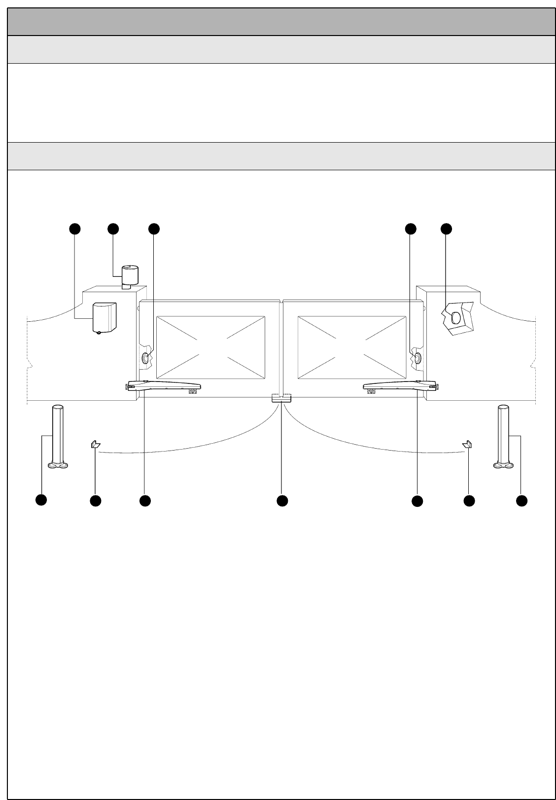
The following example of a typical WG20 application will serve to clarify a few terms and aspects of a gate automation system:
A) CL20 control unit
B) FL1 flashing light with incorporated aerial
C) Pair of PH1 photocells
D) KS1 key-operated selector switch
E) Pair of PT50 posts for photocells (not included)
F) Pair of opening stops (not included); the natural strike may be
sufficient, otherwise the mechanical stops of the gearmotor can be
used, see Figure 26
G) WG10 gearmotors
H) Closing stop (not included)
A
EF G H GFE
B C C D
Figure 1
2 Product description
2.1 Applications
WG20 is a set of components designed for the automation of single-leaf
or double-leaf gates in residential applications.
Any applications other than those described above or under dif-
ferent conditions from those specified in this manual are forbid-
den.
WG20 operates with electric power. In the event of a power failure, the
gearmotor can be released using suitable keys in order to move the gate
manually. Alternatively, the PR1 buffer battery (optional accessory) can be
used.
2.2 Description of the automation
WG20 Instructions 5
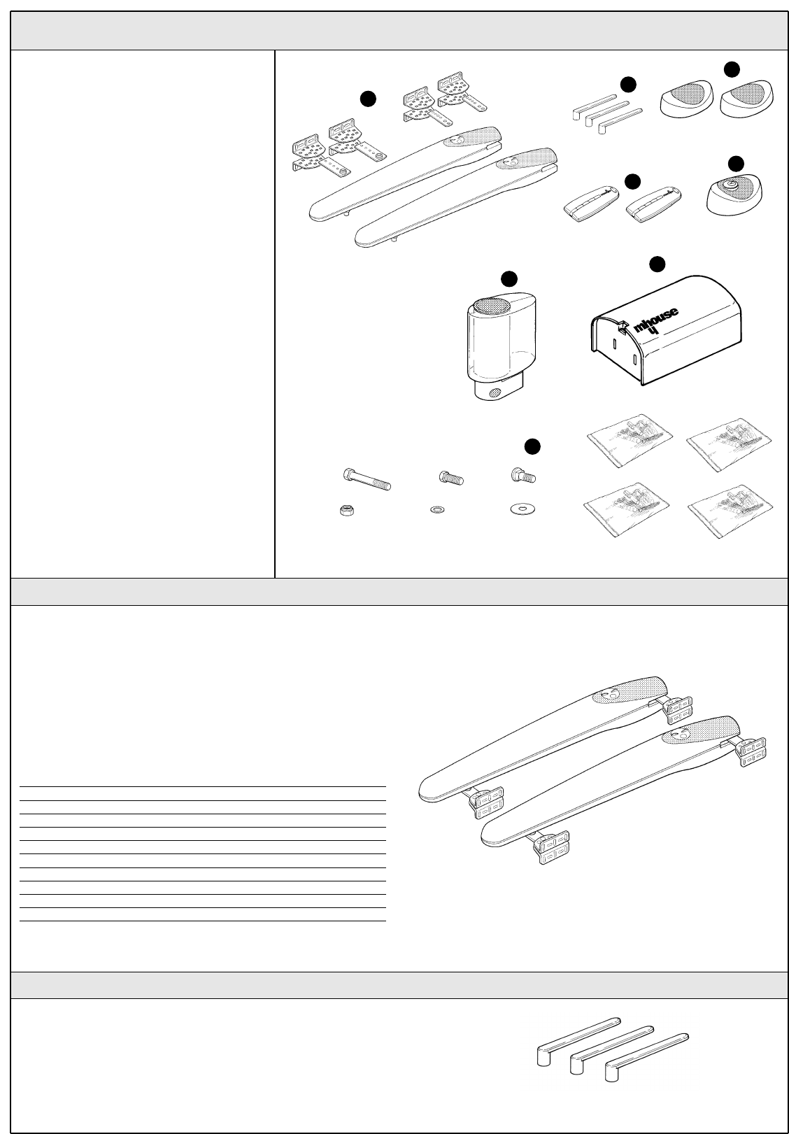
WG20 consists of the devices shown in figure 2;
make immediately sure that they correspond to
the contents of the package and verify the
integrity of the devices.
Note: to adapt WG20 to local regulations, the
contents of the package may vary; an exact list
of the contents is shown on the outside of the
package under the "Mhousekit WG10 contains"
heading.
2.3 Description of Devices
A) 2 WG10 electromechanical gearmotors
complete with mounting brackets(*)
B) 3 release keys.
C) 1 pair of PH1 photocells (consisting of a TX
and an RX).
D) 2 TX4 radio transmitters.
E) 11 KS1 key-operated selector switch and
two keys.
F) 1 FL1 flashing light with incorporated aerial.
G) 1 CL20 control unit.
H) Miscellaneous small parts: screws, screw
anchors, etc., see tables1, 2, 3, 4 and 5 (*).
(*) the screws needed to secure the front and
rear brackets are not supplied because their
type depends on the material and thickness of
the gate.
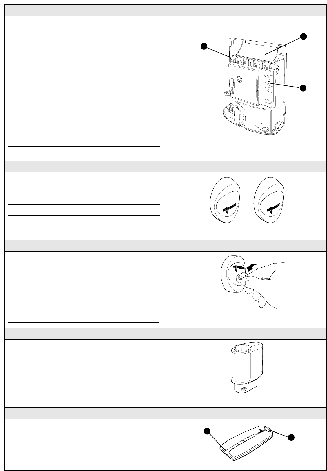
WG10 is an electromechanical gearmotor consisting of a worm screw
reduction gear and a 24Vdirect current motor. It features a key-operated
mechanical release mechanism that allows you to move the gate manu-
ally in the event of a power failure.
The gearmotor is fitted with four mounting brackets (two at the front and
two at the rear) and an adjustable stop (small plates that can be loos-
ened and adjusted on the teeth to limit the opening stroke) that offers
trouble-free installation in all conditions.
Table 1: list of small parts for two WG10 units Q.ty
M10 self-locking nuts 2 pcs.
M8 self-locking nuts 8 pcs.
Front plates 2 pcs.
Rear plates 2 pcs.
Mounting brackets 8 pcs.
10x40 hex-head screws 2 pcs.
8x10 hex-head screws 2 pcs.
8x35 carriage screws 8 pcs.
8x24 flat washers 2 pcs.
8x16 flat washers 8 pcs.
2.3.1 WG10 Electromechanical Gearmotors
The three keys enable the gearmotor to be released in the event of a
power failure.
2.3.2 Release keys
Figure 3
Figure 2
Figure 4
B
C
D
E
G
H
F
A
6 WG20 Instructions
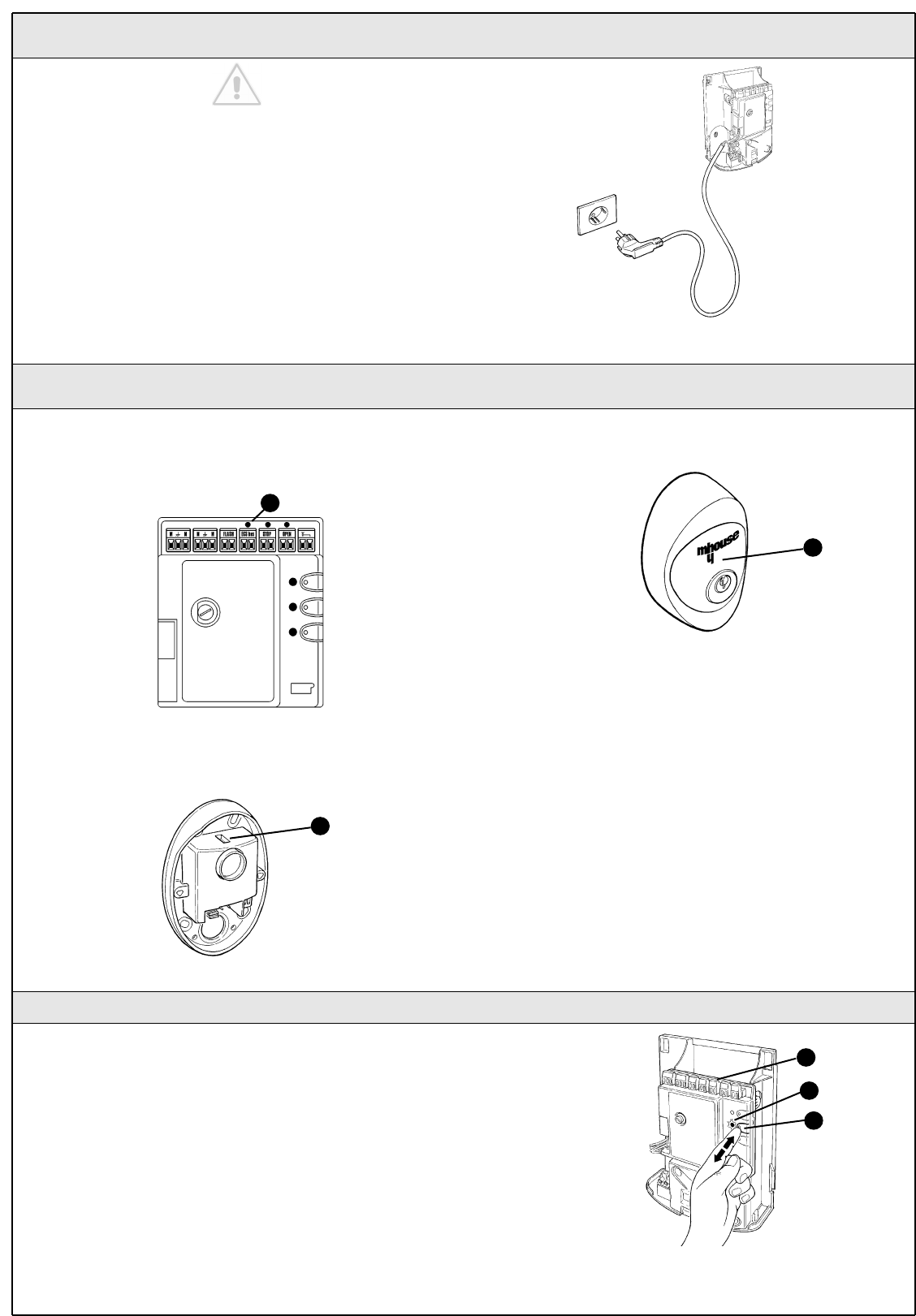
2.3.3 CL20 Control Unit
2.3.4 PH1 Photocells
The CL20 unit actuates the gearmotors and provides for the control and
supply of the different components; it features an electronic board with
incorporated radio receiver; a housing [B] for the PR1 buffer battery
(optional), which is necessary for operation in case of power failure.
The CL20 control unit can actuate the gearmotors with two speeds:
"slow" and "fast".
The three P1, P2 and P3 buttons [C] and the corresponding LED's are
used to program the control unit.
To facilitate the electrical connections there are separate terminals for
each device [A], which are removable and colour-coded based on the
function performed. Next to each input terminal there is a LED that sig-
nals its status.
The connection to the power supply is very easy: just insert the plug in a
power outlet.
Table 2: List of small parts for CL20 Q.ty
4.2X32 self-tapping screw 4 pcs.
s 6 c nylon screw anchor 4 pcs.
Figure 5
A
B
C
The pair of PH1 wall-mounted photocells, once they are connected to
the control unit, enable the detection of obstacles found on the optical
axis between the transmitter (TX) and the receiver (RX).
Table 3: List of small parts for PH1 Q.ty
3.5X25 self-tapping screw 4 pcs.
4.2X32 self-tapping screw 4 pcs.
s 5 c nylon screw anchor 4 pcs.
2.3.5 KS1 Key-Operated Selector Switch
The KS1 key-operated two-position selector switch enables gate
control without using the radio transmitter. It is equipped with internal
light for locating in the dark.
There are two commands, which depend on the direction of rotation of
the key: "OPEN" and "STOP"; then the key, which is spring loaded,
returns to the centre position.
Figure 7
Table 4: List of small parts for KS1 Q.ty
HI LO 4X9.5 screw 2 pcs.
3.5X25 self-tapping screw 4 pcs.
s 5 c nylon screw anchor 4 pcs.
2.3.6 FL1 Flashing Light with Incorporated Aerial
Table 5: List of small parts for FL1 Q.ty
4.2X32 self-tapping screw 4 pcs.
s 6 c nylon screw anchor 4 pcs.
The flashing light is controlled by the CL20 control unit and signals
danger when the gate is moving. Inside the flashing light there is also
the aerial for the radio receiver.
Figure 8
2.3.7 TX4 Radio Transmitters
The radio transmitters are used for the remote control of the gate
opening and closing manoeuvres. They feature four buttons that can all
be used for the 4 types of command to a single automation unit, or to
control up to 4 different automation units.
The transmission of the command is confirmed by the LED [A]; an eyelet
[B] allows them to be hung on a keyring. Figure 9
A
B
Figure 6
WG20 Instructions 7
The installation must be carried out by qualified and skilled
personnel in compliance with the directions provided in chapter
1 "WARNINGS".
3 Installation
3.1 Preliminary checks
WG20 must not be used to power a gate that is not efficient and
safe. It cannot solve defects resulting from incorrect installation
or poor maintenance of the gate.
Before proceeding with the installation you must:
• Make sure that the weight and dimensions of the gate fall within
the specified operating limits. If they do not, WG20 cannot be
used.
• Make sure that the structure of the gate is suitable for
automation and in compliance with regulations in force.
• Make sure that there are no points of greater friction in the
opening or closing travel of the gate leaves.
• Make sure that the gate is well balanced: it must not move by
itself when it is placed in any position.
• Make sure that the mounting positions of the various devices are
protected from impacts and that the surfaces are sufficiently sturdy.
• Make sure that the mounting surfaces of the photocells are flat
and that they enable the proper alignment between TX and RX.
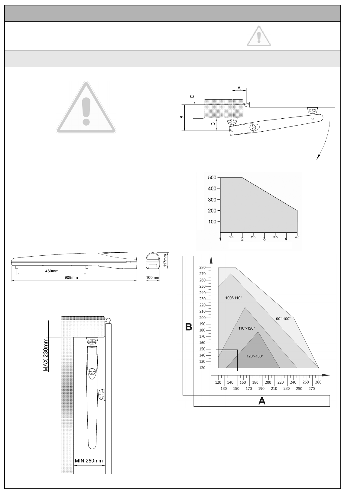
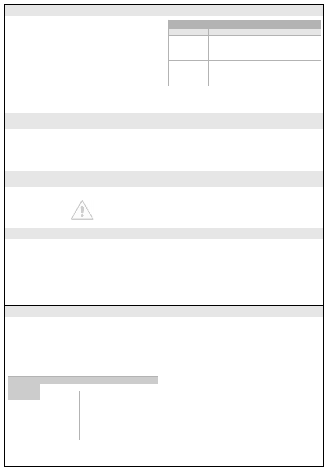
• Check the size limits referring to Figure 10.
• Make sure there is enough space even when the gate is open.
• Using the leaf opening angle as a guideline, check that the
values in Table 6 can be met.
Figure 10
Figure 11
• "C" depends on how the rear bracket is mounted (see Figure 17) and
may vary from 53 mm to 176 mm. It is normally about 150mm.
• "D" is easy to measure on the gate.
• "A" is the sum of "C" and "D".
• The value of "B" can be calculated from the value of "A" and the
opening angle of the leaves. For example: if "A" is 150mm and the
opening angle of the leaves is 100°, the value of "B" is about 150mm.
Make sure that "B" is equal or similar to "A". This ensures the leaf moves
smoothly, thereby reducing the strain on the gearmotor.
Table 6
Figure 12
Maximum leaf weight (Kg)
Maximum leaf length (m)
8 WG20 Instructions
3.1.1 Operating Limits
Chapter 6 "Technical Characteristics" provides the fundamental data
needed to determine whether all the WG20 components are suitable for
the intended application.
In general, WG20 is suitable for the automation of gates featuring leaves
up to 4,5m wide, weighing up to 400 kg, with opening angle of up to
130° for residential applications.
The shape of the gate and the climatic conditions (e.g. presence of
strong wind) may reduce these maximum limits. In this case it is
necessary to measure the torque needed to move the leaves under the
worst conditions, and to compare it to the data provided in the technical
characteristics chart for the WG20 gearmotor.
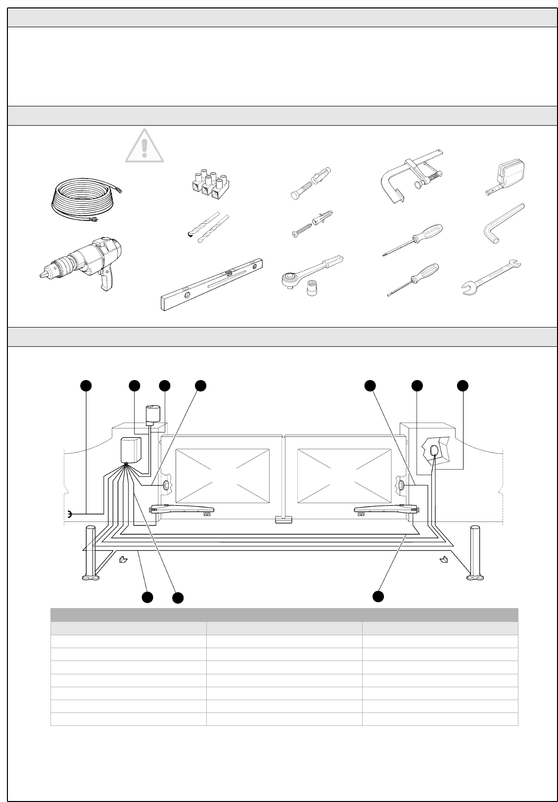
3.1.2 Tools and Materials
Make sure you have all the tools and materials needed to install
the system; make sure that they are in good condition and
serviceable according to current safety standards. See examples
in Figure 13.
3.1.3 List of Cables
The cables required for the installation of WG20 may vary depending on the type and quantity of devices to be installed; figure 14 shows the cables
needed for a typical installation; no cable is supplied with WG20.
Table 7: list of cables
Connection Cable type Maximum length allowed
[A] Power supply line 3x1.5mm2cable 30m (note 1)
[B] FLASH light output 2x0,5mm2cable 20m
[C] Radio aerial RG58 type shielded cable 20m (recommended less than 5m)
[D] ECSBus input/output 2x0,5mm2cable 20m (note 2)
[E] STOP input 2x0,5mm2cable 20m (note 2)
[F] OPEN input 2x0,5mm2cable 20m (note 2)
[G] M1 and M2 motors output 3x1mm2cable 10m
WARNING: the cables used must be suitable for the type of installation; for example, an H03VV-F type cable is recommended for indoor
applications, while H07RN-F is suitable for outdoor applications.
Note 1 A power supply cable longer than 30 m may be used provided it has a larger gauge, e.g. 3x2.5mm2, and that a safety grounding system
is provided near the automation unit.
Note 2 For the ESCbus, STOP and OPEN cables, there are no special contraindications to the use of a single cable that groups together multiple
connections; for example, the STOP and OPEN inputs can be connected to the KS1 selector switch using a single 4x0,5mm2cable.
Figure 13
B C DA ED
DGG
F
Figure 14
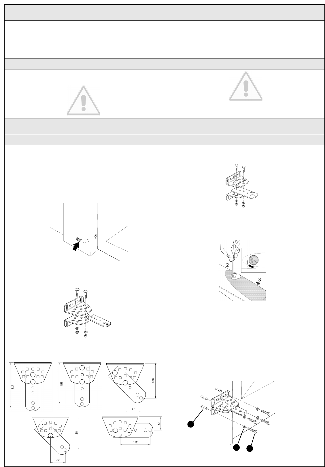
1 Choose the mounting position in accordance with the specifications in
paragraph 3.1 "Preliminary Checks".
2 Check that the mounting surface is perfectly smooth, vertical and
sufficiently compact. WG10 does not come with a mounting system,
consequently one will have to be chosen according to the surface
material.
3 Lay the conduit for the power cable.
4 To obtain the rear supports, assemble two brackets and the rear plate
as shown in Figure 16.
5 To obtain different "C" values (see Figure 12) assemble the brackets and
plate as shown in Figure 17.
6 To obtain the front support, assemble two brackets and the front plate
as shown in Figure 18.
7 Remove the back cover of the gearmotors by sliding it in the direction
of the arrows.
8 Move the leaves to the "gate closed" position.
9 Referring to the "B" distance calculated from Table 6, place the rear
support in the correct position on the mounting surface, Check that there
is a suitable surface at the values in Figure 22, i.e. where the front
support is mounted.
10 Mark the drill points for the rear support using the support itself as a
reference point. Drill holes in the mounting surface for 4 anchors [A] with
a diameter of at least 8 mm (not included in supply). Fix the plate with
suitable screws [C] and washers [B].
WG20 Instructions 9
With the exception of the power line that supplies the control unit, the
rest of the system uses extra-low voltage (approx. 24V); the wiring can
therefore be done by personnel that is not properly qualified, provided
that all the instructions in this manual are carefully observed.
After selecting the position of the various devices (refer to figure 1) you
can start preparing the conduits for the electrical cables connecting the
devices to the control unit.
The conduits are designed to protect the electrical cables and prevent
accidental breakage, which may be caused by the passage of vehicles,
for instance.
3.2 Preparing the Electrical System
Although the connection of WG20 to the electrical mains is beyond the
scope of this manual, we wish to remind you that:
• The power supply line must be laid and connected by a qualified
professional electrician.
• Alternatively, have a suitably protected 16A "shuko" outlet
installed, where you can plug in WG20.
• The electric line must be grounded and protected against short
circuits; a bipolar disconnection device must also be present with
contact separation of at least 3 mm, which allows the power sup-
ply to be disconnected during the installation and maintenance of
the WG20.
3.2.1 Connection to the Electrical Mains
3.3 Installation of the Various Devices
3.3.1 WG10 gearmotor mounting
Figure 15
Figure 16
Figure 18
Figure 19
Figure 17 Figure 20
A
BC
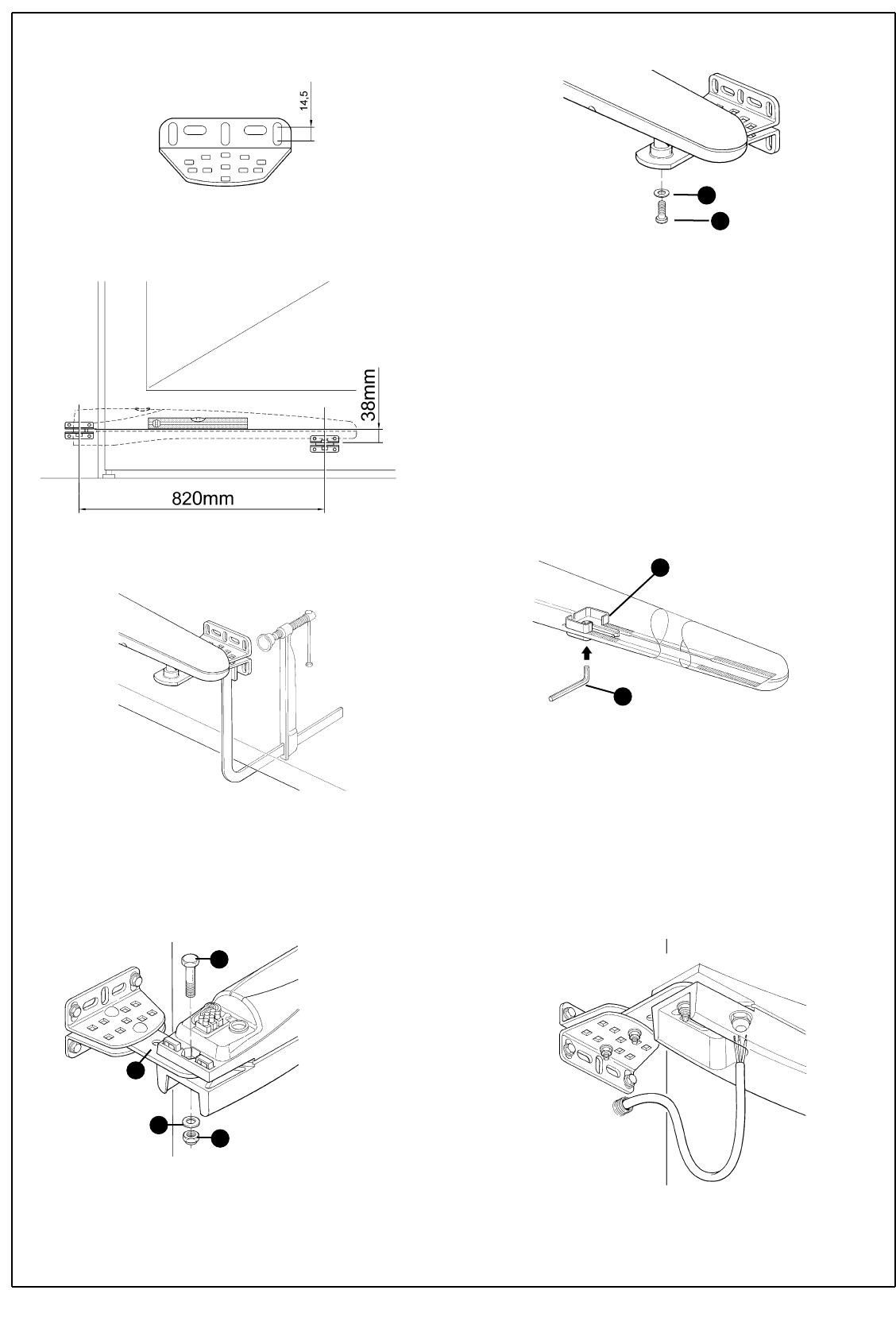
11 Check that the plate is perfectly level, the slots on the bracket allow
small differences in alignment to be corrected.
12 Referring to Figure 22, place the front support at a distance of 820
mm from the rear support and 38 mm lower.
13 Temporarily fix the front support to the leaf with a clamp.
14 Lift up the gearmotor and fit the fork into the hole in the front support.
15 Keep the gearmotor lifted and pull it to open the gate until the hole in
the plate matches the hole in the gearmotor. Fix the gearmotor to the
rear support [E] with the screw [D], nut [G] and washer [F].
16 Firmly tighten the nut and then loosen it by about half a turn in order
to allow the gearmotor to rotate on the support.
17 Fix the gearmotor to the front support and anchor it with the screw [I]
and washer [H]. Fully tighten the screw.
18 Release the gearmotors using the appropriate release keys (see the
"Gearmotor Release" paragraph on page 34).
19 Test the mechanism by moving the gate by hand. Check that the fork
slides perfectly on the worm screw of the gear motor and that there
remains a margin of at least 5 mm from the opening and closing stops,
making sure, however, that not too much of the worm screw remains
unused.
20 If necessary, test the other assembly positions allowed by the front
and rear plates. See Figure 17.
21 If necessary, adjust the stops by loosening them with Allen keys [N]
and moving them to the required position. The opening stop [L] is used
if there are no opening stops on the ground. Normally, the leaves stop
against the closing stop during the closing manoeuvre. After adjusting
the stops, fully tighten the screws.
22 Secure the front support permanently using screws suited to the
material of which the gate is constructed.
23 Fix the gearmotor once more using the appropriate release keys (see
the "Gearmotor release" paragraph on page 34).
24 Thread the electrical cable through the conduit and bring it to the
control unit.
N.B.: the cable leaving the gear motor must be curved so that it can
follow the gearmotor when it rotates to open and close the leaf.
Figure 21
Figure 23
Figure 24
Figure 25
Figure 26
Figure 22
Figure 27
10 WG20 Instructions
D
E
F
G
H
I
N
L
WG20 Instructions 11
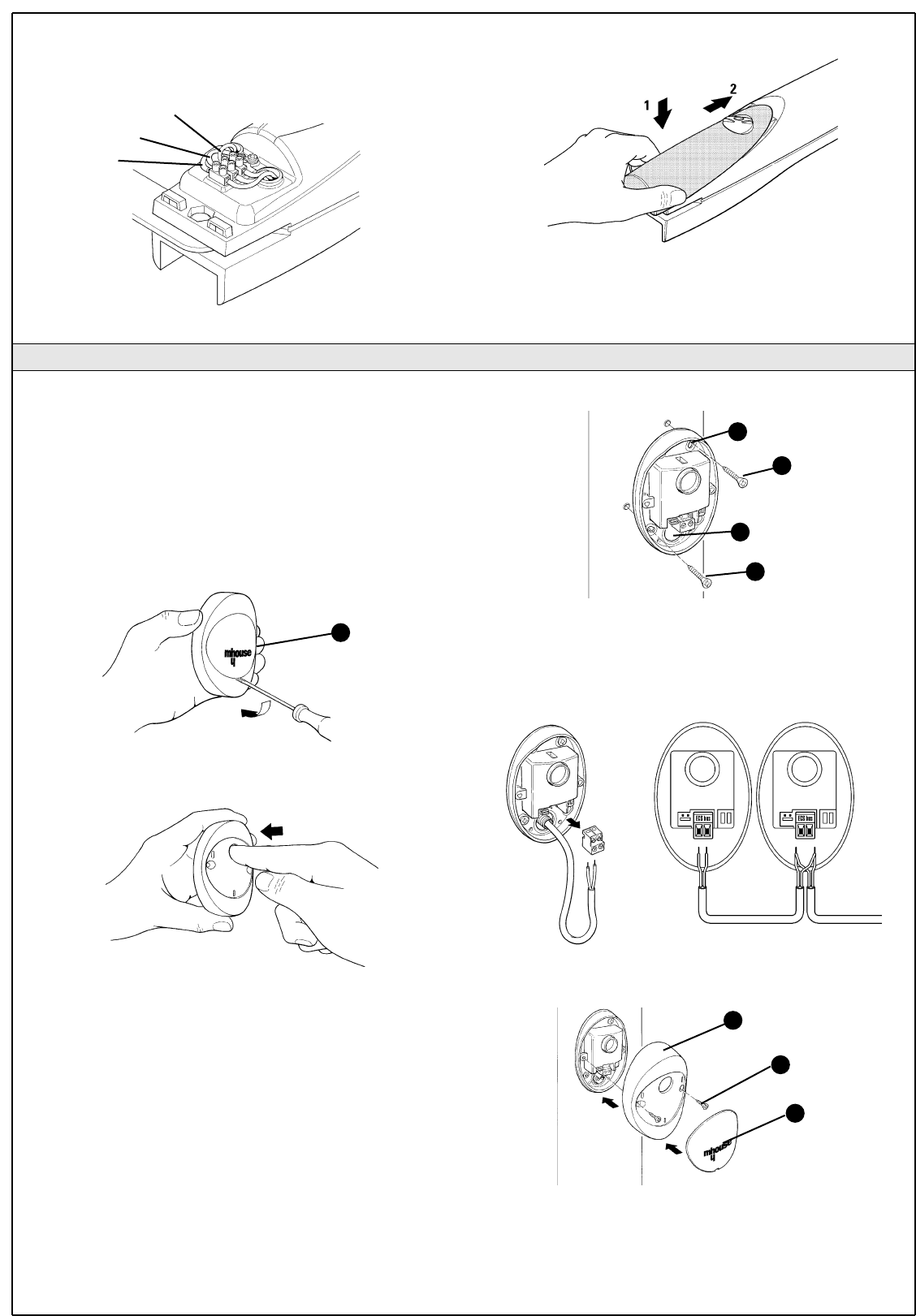
1 Select the position of the two elements that make up the photocell (TX
and RX) observing the following directions:
• Position them at a height of 40-60 cm from the ground, on both
sides of the area to be protected, on the street side of the installation and
as close as possible to the edge of the gate, no farther than 15 cm.
• Point transmitter TX towards receiver RX, with a maximum tolerance
of 5°.
• In the selected locations there must be a conduit for threading the cables.
2 Remove the front glass [A] by prising it out with a slotted tip
screwdriver applied to the bottom.
3 Press the lens in order to separate the two shells.
4 Breach two of the four holes [B] at the bottom with a screwdriver.
5 Position the photocell at the point where the conduit arrives; the hole
at the bottom [D] should match the point where the cables come out of
the wall; mark the drilling points using the bottom as reference.
6 Drill the holes in the wall using a hammer drill with a 5 mm bit and insert
the 5 mm screw anchors.
7 Secure the bottom with the screws [C].
8 Connect the electric cable to the appropriate TX and RX terminals.
From an electrical viewpoint, TX and RX must be connected in parallel as
shown in Figure 33. It is not necessary to observe any polarity. The
terminals can be removed in order to facilitate the operations; make the
connections and then reinsert them.
9 Secure the cover shell [E] using the two screws [F] and a Phillips
screwdriver. Then insert the glass [G], pressing it gently to close it.
25 Loosen the cable gland under the gearmotor, push the power cable
through and then firmly close the cable gland.
26 Make electrical connections as follows.
27 Close the back cover of the gearmotors by inserting it in the direction
of the arrows.
Figure 28
3.3.2 Photocells
A
Figure 29
Figure 30
Figure 31
Figure 32
Figure 33
Figure 34
B
C
D
C
E
F
G
TX RX
brown
blue
yellow-green
12 WG20 Instructions
1 Determine the position of the flashing light: it should be near the gate
and easy to see; it can be secured to a horizontal as well as vertical
surface.
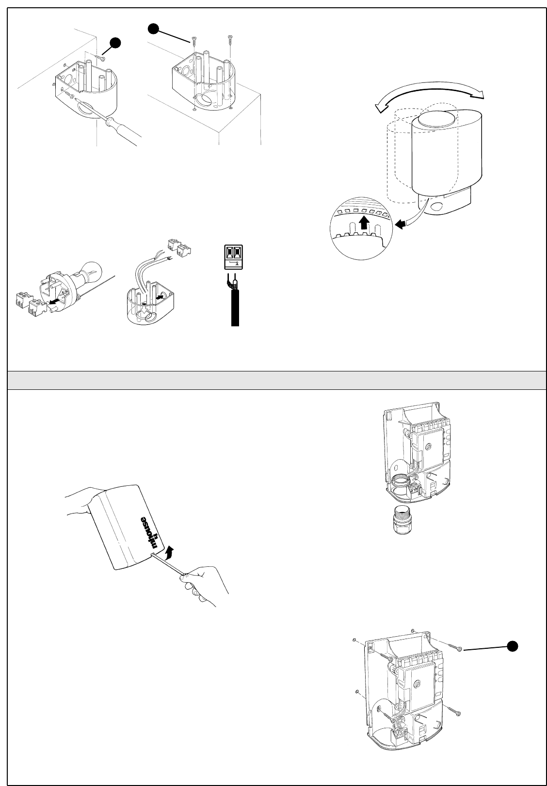
2 Slide out the diffuser [A] from the bottom by pressing the two buttons
[B].
3 Separate the lamp holder with the aerial from the base.
4 Breach the four holes for the screws and the hole for the passage of
the cables in the bottom or side, depending on the installation position,
using a screwdriver.
5 Mark the drilling points using the bottom as reference and make sure
that the hole in the bottom matches the outlet for the cables.
6 Drill the holes in the wall using a hammer drill with a 6 mm bit and insert
the 6 mm screw anchors
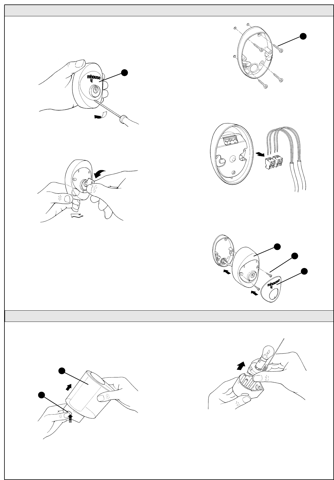
1 Determine the position of the selector switch; it must be installed
outdoors, alongside the gate and at a height of approx. 80 cm, so that
it can be used by people of different height.
2 Remove the front glass [A] by prising it out with a slotted tip
screwdriver applied to the bottom.
3 To separate the bottom from the shell you need to insert the key and keep it
turned, then pull with a finger inserted in the hole for the passage of the cables.
4 Breach the four holes at the bottom with a screwdriver; mark the
drilling points using the bottom as reference; make sure that the hole in
the bottom matches the outlet for the cables.
5 Drill the holes in the wall using a hammer drill with a 5 mm bit and insert
the 5 mm screw anchors
6 Secure the bottom using the four screws [B].
7 Connect the electric cables to the appropriate OPEN and STOP
terminals, as shown in figure 38. It is not necessary to observe any
polarity. The terminals can be removed in order to facilitate the
operations; make the connections and then reinsert them.
8 To insert the shell on the bottom you need to turn the key. After you
have inserted it, turn the key back to the centre position.
9 Secure the body [C] using the two screws [D] and a Phillips
screwdriver. Finally insert the glass [E], pressing it gently to close it.
3.3.3 KS1 Key-Operated Selector Switch
Figure 35
Figure 36
Figure 37
Figure 38
3.3.4 FLI Flashing Light
Figure 39
A
B
E
D
C
Figure 40
Figure 41
A
B
WG20 Instructions 13
7 Secure the bottom with the screws [C].
8 Connect the electrical cables to the appropriate FLASH and "aerial"
terminals as shown in figure 43. You do not need to observe any polarity
on the FLASH terminal; however, for the connection of the shielded cable
to the aerial, connect the braid as shown in figure 44. The terminals can
be removed in order to facilitate the operations; make the connections
and then reinsert them.
9 Fit the lamp holder on the base and press it down until it snaps into
position.
10 Slide in the diffuser, pressing the buttons and fitting it on the bottom.
Rotate it in the desired direction then press it down until the two buttons
snap into their seat.
Figure 42
Figure 45
C
C
3.3.5 CL20 Control Unit
1 Select the installation position in a location protected from possible
impacts and near the gate so that the length of the cables can be
reduced.
2 Remove the cover by prising it open with a screwdriver applied to the
bottom opening, slide it out a few centimetres and then lift it from the
bottom .
3 Arrange the conduit for the electric cables so that they can be let in
through the bottom of the control unit as shown in figure 47.
4 Drill a hole through the bottom of the control unit and use suitable
unions to fasten the conduits for the electric cables.
5 Breach the two bottom holes using a screwdriver, then mark the drilling
points using the bottom as reference.
6 Drill the holes in the wall using a hammer drill with a 6 mm bit and insert
the 6 mm screw anchors
7 Secure the bottom with the appropriate screws [A].
Figure 46
Figure 47
Figure 48
A
Figure 43 Figure 44
14 WG20 Instructions
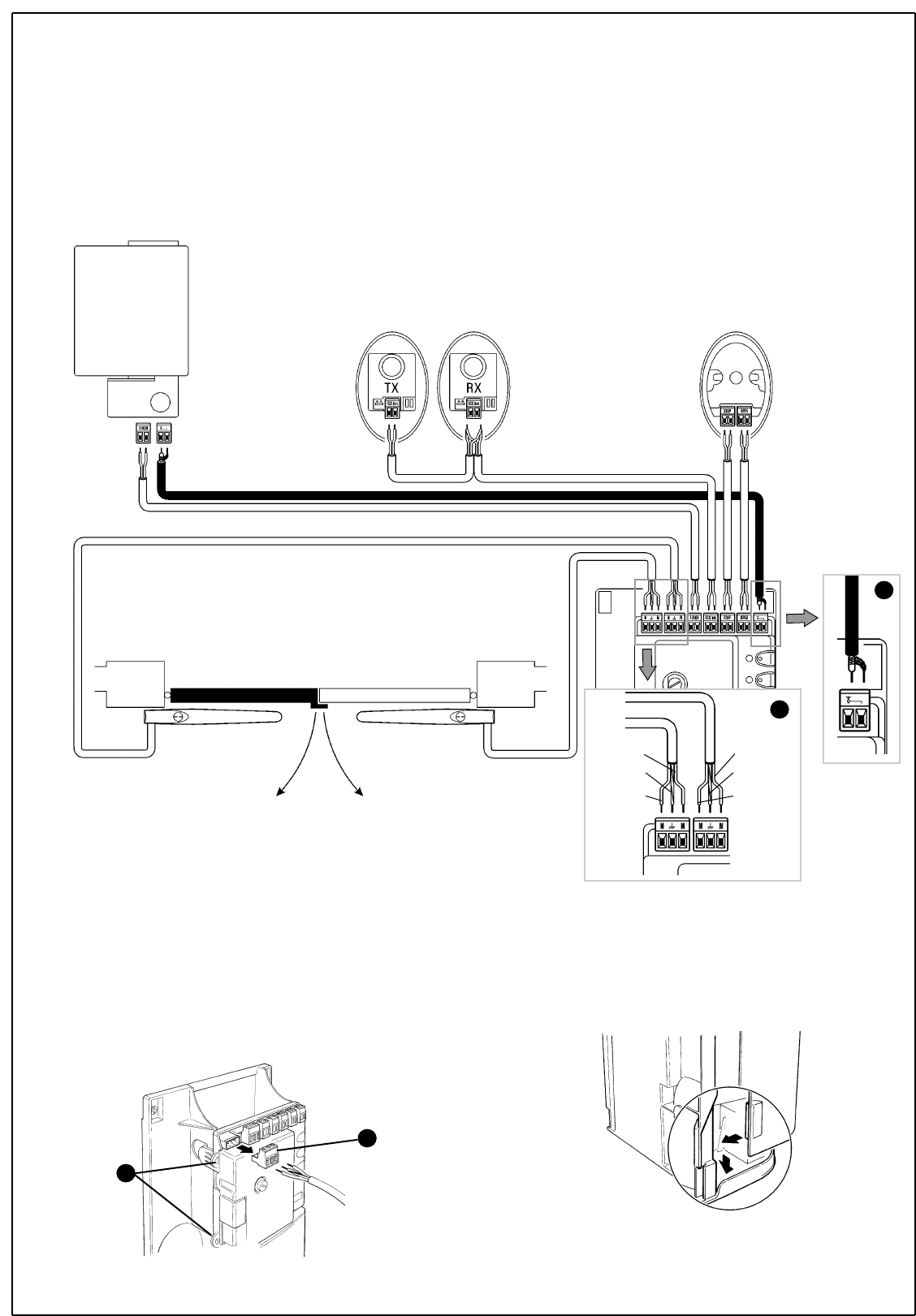
8 Refer to figure 49 for the electrical extra low voltage connection of the
various devices to the CL20 control unit terminals.
• The terminals have the same colour coding as the corresponding
devices; for example, the grey terminal (OPEN) of the KS1 selector
switch must be connected to the grey terminal (OPEN) of the control
unit.
• For most connections you do not need to observe any polarity; only
for the shielded cable of the aerial it is necessary to connect the central
core and the shield as shown in detail [B]. The cable for the motors must
be connected as shown in detail [A].
• Keep in mind that, to prevent the jamming of the two leaves, the
control unit commands the M2 motor to open first, followed by M1 (vice-
versa for the closing manoeuvre). Therefore make sure that the motor
that drives the leaf that strikes the mechanical stop is connected to
terminal M1 (outer one), while the motor that drives the other leaf must
be connected to terminal M2.
• If only one motor is used (single-leaf gate) it must be connected to
terminal M2 while terminal M1 remains free.
FL1
PH1 PH1 KS1
WG10
M2
WG10
M1
To facilitate the installation operations, the terminals [B] can be removed
as shown in figure 49; make the connections and then re-insert them.
When you have completed the connections, use clamps to secure the
cables to the appropriate fasteners [C].
9 To close the control unit you need to rest the cover on the bottom
approximately 3 cm above the final position, then press it down until it
snaps into place.
C
B
Figure 50
Figure 51
Figure 49
brown
yellow/green
blue
brown
yellow/green
blue
A
B
WG20 Instructions 15
3.4 Power Supply Connection
3.5 Initial checks
The connection of the CL20 control unit to the mains must be
made by a qualified electrician.
To carry out tests, insert the plug for CL20 in a power outlet; if neces-
sary, use an extension cord.
The CL20 control unit must be permanently connected to the mains
power supply for the testing and commissioning operations.
This operation must be performed as follows by a qualified electrician:
1 Make sure that the plug of the CL20 control unit is not plugged into the
power socket
2 Disconnect the power cable from the CL20 control unit power supply
terminal
3 Slacken the collar close to the terminal and remove the cable
4 Insert the final power supply cable of the control unit through the collar
5 Connect the cable to the terminal of the control unit
6 Tighten the collar Figure 52
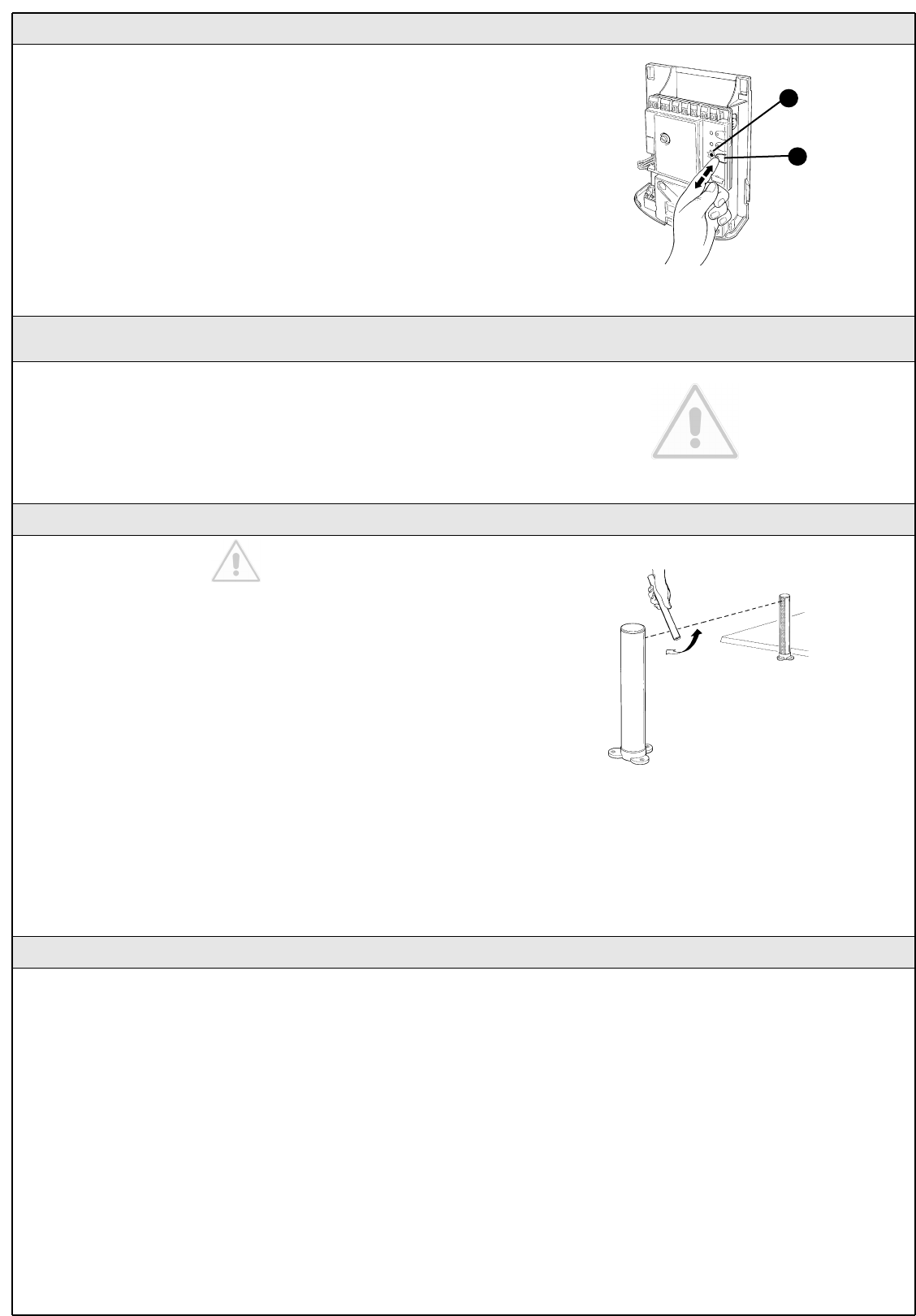
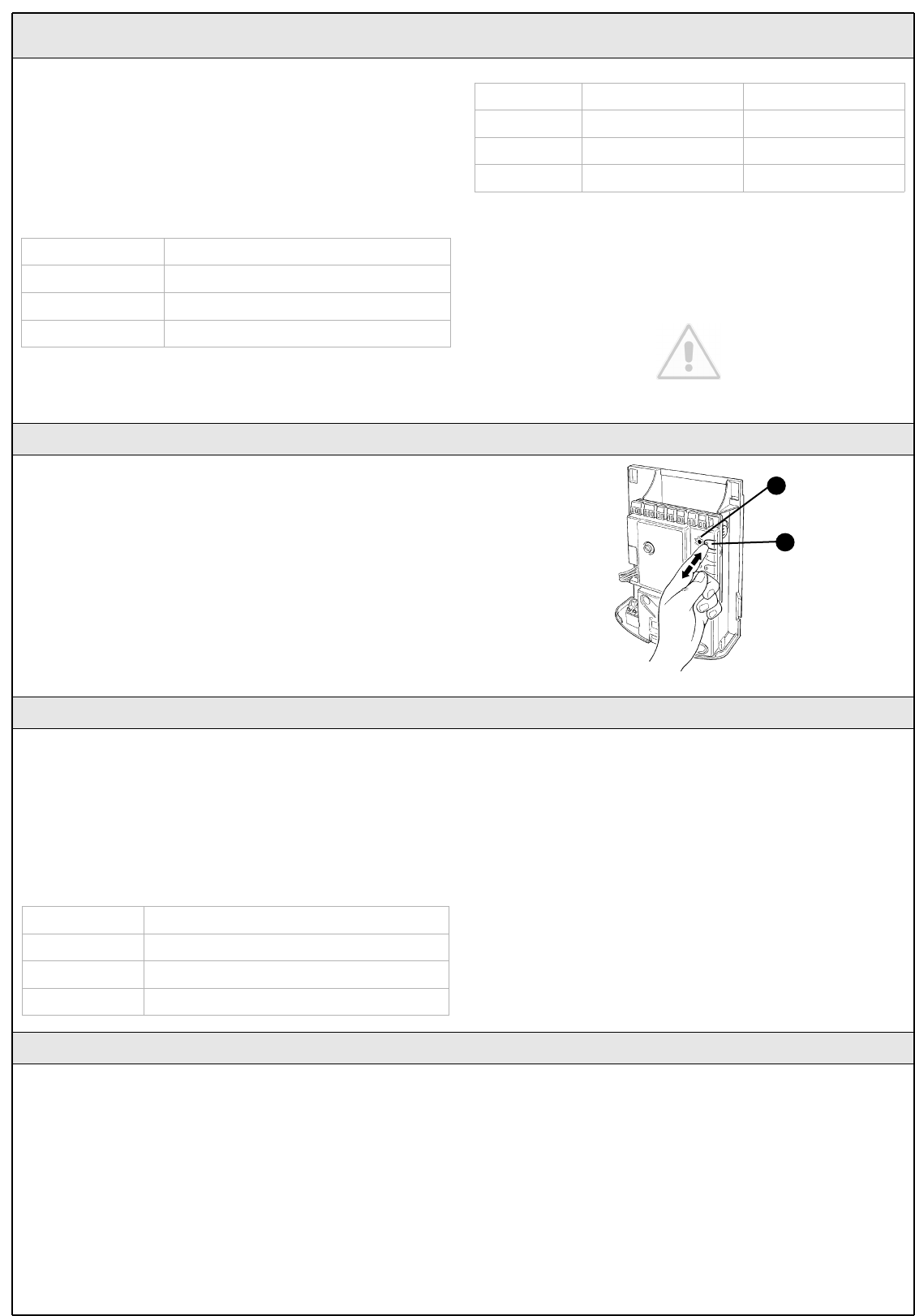
As soon as the CL20 control unit is energized, you should check the
following:
1 Make sure that the "ECSBus" LED [A] flashes regularly, with about one
flash per second.
2 Make sure that the SAFE LED [B] on the photocells flashes (both on TX
and RX); the type of flashing is not important as it depends on other factors;
what is important is that the LED should not be steadily on or steadily off.
3 Make sure that the night light [C] on the KS1 key-operated selector
switch is on.
4 If the above conditions are not satisfied, you should immediately switch
off the power supply to the CL20 control unit and check the cable
connections more carefully. For more useful information see also
chapters 5.5 "Troubleshooting" and 5.6 "Diagnostics and Signals".
Figure 55
Figure 54
B
C
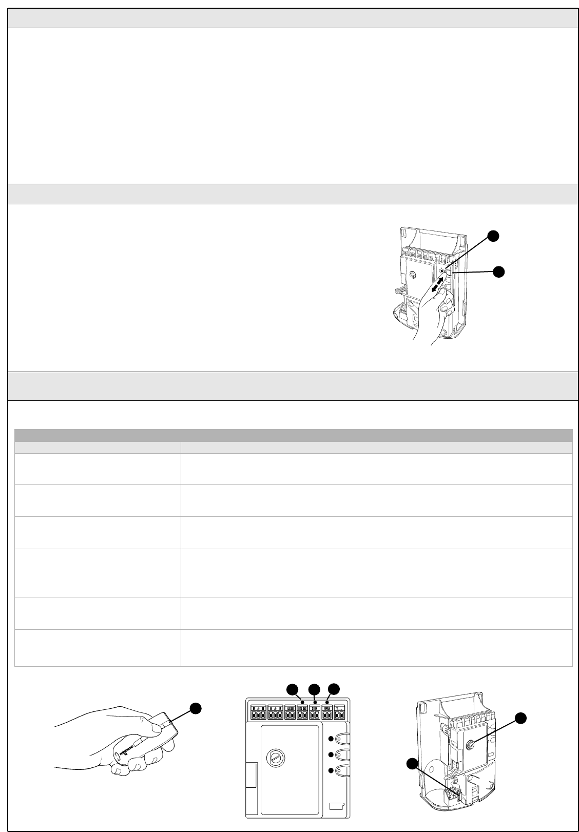
3.5.1 Recognition of Connected Devices
When you have completed the initial checks, the control unit must
recognize the devices connected to it on the "ECSBus" and "STOP"
terminals.
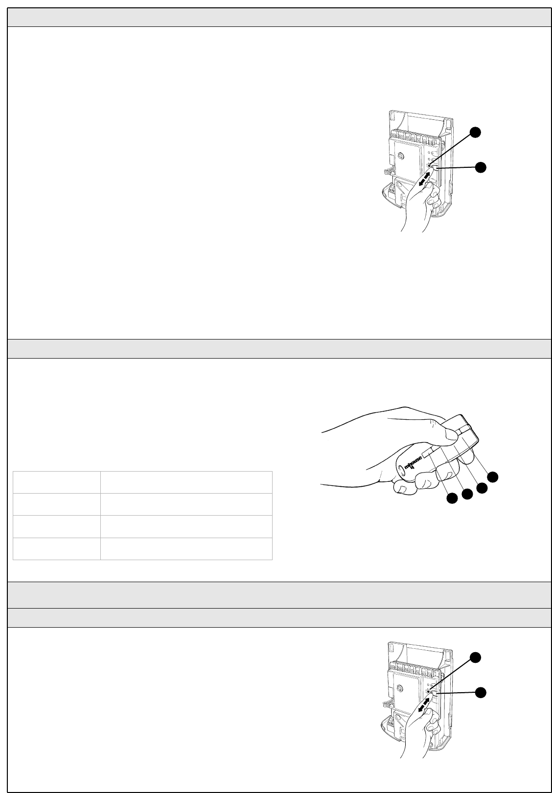
1 On the control unit, press the P2 button [C] and hold it down for at
least three seconds, then release the button.
2 Wait a few seconds for the control unit to finish recognizing the
devices.
3 When the learning procedure is completed, the STOP LED [A] must
remain on, while the P2 LED [B] must go off. If the P2 LED flashes it
means that an error has occurred: see paragraph 5.5 "Troubleshooting".
The connected devices recognition stage can be repeated again at any
time, even after the installation (for example, if an additional photocell is
installed); just repeat the procedure starting from step 1.
Figure 56
B
A
C
A
Figure 53
16 WG20 Instructions
3.5.3 Checking the Radio Transmitters
After recognizing the devices, the control unit must learn to recognize the
leaves' opening and closing angles .
During this stage, the leaves' opening angle is measured from the
closing mechanical stop to the opening mechanical stop.
Fixed and sufficiently sturdy mechanical stops are required.
1 Release the motors using the appropriate keys (see the "Gearmotor
Release" paragraph on page 34) and move the leaves to mid travel so
that they are free to move in both opening and closing directions; then
lock the motors.
2 On the control unit press the P3 button [B] and hold it down for at least
three seconds, then release the button.
Wait for the control unit to complete the recognition stage: closing of the
M1 motor to the mechanical stop, closing of the M2 motor to the
mechanical stop, opening of the M2 and M1 motors to the opening
mechanical stop; complete closing of M1 and M2.
• If the first manoeuvre of one or both leaves is not to close, press P3
to interrupt the recognition stage, then switch the polarity of the motor/s
that opened by exchanging the two brown and blue wires on the
terminal.
• If the first motor to move in the closing direction is not M1, press P3
to interrupt the recognition stage, then switch the motor connections on
the terminals.
• If any device is triggered during the recognition stage (photocells, key-
operated selector switch, pressure on P3, etc.), the recognition stage will
immediately be interrupted. It will therefore be necessary to start again
from the beginning.
3 If at the conclusion of the search the P3 LED [A] flashes, it means that
an error has occurred; see paragraph 5.5 "Troubleshooting".
The opening angles recognition stage can be repeated again at any time,
even after the installation (for example, if one of the opening stops is
moved); just repeat the procedure starting from step 1.
3.5.2 Recognition of Gate Leaves' Opening and Closing Angles
Figure 57
B
A
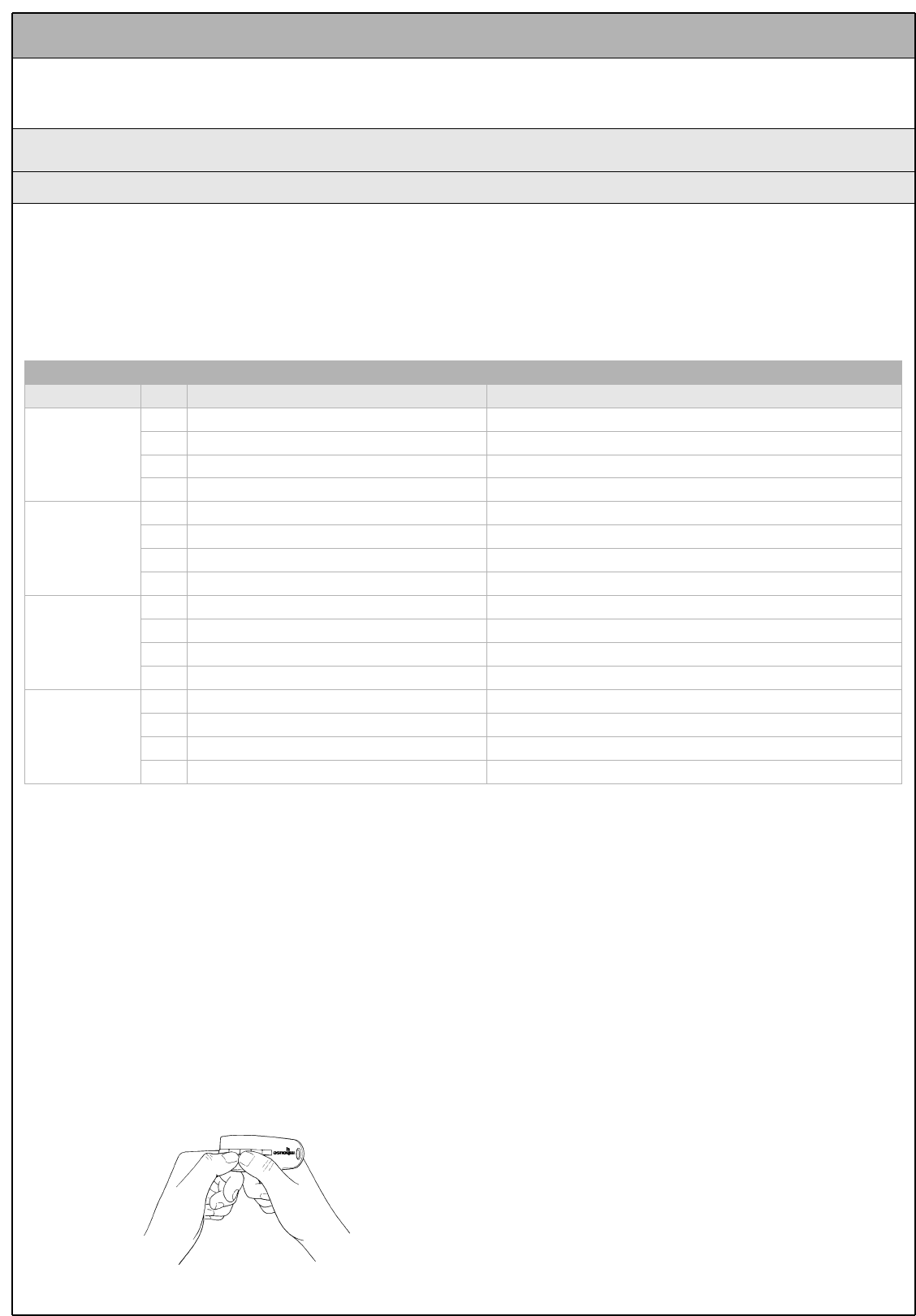
To check the transmitters just press one of the four buttons, make sure
that the red LED flashes and that the automation executes the
command.
The command associated to each button depends on how they have
been memorized (see paragraph 5.4 "Memorization of Radio
Transmitters"). The transmitters supplied have already been memorized
and when you press the buttons the following commands are
transmitted:
Button T1 "OPEN" command
Button T2 "Open pedestrian gate" command
Button T3 "Open only" command
Button T4 "Close only" command
3.6 Regulations
3.6.1 Selecting the Speed of the Leaf
The leaves can be opened and closed at two speeds: "slow" or "fast".
To switch from one speed to the other press the P2 button [B]
momentarily; the corresponding P2 LED [A] will light up or go off; if the
LED is off the speed is "slow", if the LED is on the speed is "fast".
Figure 59
B
A
T1
T2
T3
T4
Figure 58
Istructions WG20 17
1 Make sure that the provisions contained in chapter 1
"WARNINGS" have been carefully observed.
2 Using the selector switch or the radio transmitter, test the opening and
closing of the gate and make sure that the leaves move in the intended
direction.
The test should be carried out a number of times to make sure that the
gate moves smoothly, that there are no points of excessive friction and
that there are no defects in the assembly or adjustments.
3 Check the proper operation of all the safety devices, one by one
(photocells, sensitive edges, etc.). In particular, each time a device is
activated the "ECSBus" LED on the control unit flashes for a longer time,
confirming that the control unit recognizes the event.
4 To check the photocells and make sure that there is no interference
with other devices, pass a 5 cm diameter, 30 cm long cylinder on the
optical axis, first near TX, then near RX and finally at the mid-point
between them and make sure that in all these cases the device is
triggered, switching from the active to the alarm status and vice-versa;
finally, that it causes the intended action in the control unit, for example
that it causes the reversal of the movement during the closing
manoeuvre.
5 Measure the impact force according to EN 12445 standard. If "motor
force" control is used to assist the system for the reduction of the impact
force, try to find the adjustment that gives the best results.
3.6.2 Selecting the Type of Operating Cycle
The opening and closing of the gate can take place according to different
operating cycles:
• Single cycle (semiautomatic): the gate opens with a command and
stays open until the next command is given, causing it to close.
• Complete cycle (automatic closing): the gate opens with a command
and then closes automatically after a short time (for the time, see
paragraph 5.1.1 "Adjusting the Parameters with the Radio Transmitter").
To switch from one operating cycle to the other, press the P3 button [B]
momentarily; the corresponding LED [A] will light up or go off; if the LED
is off the cycle is "single", if the LED is on the cycle is "complete".
Figure 60
B
A
3.7 Testing and commissioning
These are the most important operations, designed to guarantee the
maximum safety and reliability of the automation system.
The testing procedure can also be used as a periodic check of the
devices that make up the automation.
The testing and commissioning operations must be performed by
qualified and experienced personnel who must establish what
tests should be conducted based on the risks involved, and verify
the compliance of the system with applicable regulations,
legislation and standards, in particular with all the provisions of
EN 12445 standard which establishes the test methods for gate
automation systems.
3.7.1 Testing
3.7.2 Commissioning
Figure 61
The commissioning operations can be performed only after all
the tests have been successfully carried out. Partial
commissioning or implementation of "temporary" conditions are
not permitted.
1 Prepare the technical documentation for the automation, which must
include at least: assembly drawing (e.g. figure 1), wiring diagram (e.g.
figure 14), analysis of hazards and solutions adopted, manufacturer's
declaration of conformity of all the devices installed. For WG20 use
Annexe 1 "EC Declaration of Conformity of the WG20 components".
2 Post a label on the gate providing at least the following data: type of
automation, name and address of manufacturer (person responsible for
the "commissioning"), serial number, year of manufacture and "CE"
marking.
3 Fill out the declaration of conformity and deliver it to the owner of the
automation system; for this purpose you can use Annexe 2 "EC
Declaration of Conformity".
4 Prepare the operating guide and deliver it to the owner of the
automation system; Annexe 3 "OPERATING GUIDE" can be used as an
example.
5 Prepare the maintenance schedule and deliver it to the owner of the
automation system; it must provide directions regarding the
maintenance of all the automation devices.
6 Before commissioning the automation system inform the owner
regarding dangers and hazards that are still existing.

18 WG20 Instructions
The maintenance operations must be performed in strict
compliance with the safety directions provided in this manual and
according to the applicable legislation and standards.
The devices used for the WG20 automation system do not require any
special maintenance. However, periodically make sure (at least once
every six months) that all the devices are perfectly efficient. To this end,
carry out all the tests and checks described in paragraph 3.7.1 "Testing"
and the operations described in paragraph 7.3.3 "Maintenance
Operations to Be Performed by the User".
If other devices are present, follow the directions provided in the
corresponding maintenance schedule.
4 Maintenance
4.1 Dismantling and Disposal
WG20 is constructed of various types of materials, some of which can
be recycled (aluminium, plastic, electric cables), while others must be
disposed of (electronic boards).
WARNING: some electronic components may contain polluting
substances; do not pollute the environment. Enquire about the
recycling or disposal systems available for WG20 in compliance
with regulations locally in force.
1 Contact a qualified electrician regarding the disconnection of the
automation system from the electric mains.
2 Disassemble all the devices and accessories, following in reverse order
the procedures described in chapter 3 "Installation".
3 Remove the batteries from the radio transmitters.
4 Remove the electronic boards.
5 Sort the various electrical and recyclable materials and consign them
to licensed firms for recovery and disposal.
6 Consign the remaining materials to authorized scrap collection centres.
WG20 Instructions 19
The radio transmitter can be used to adjust certain control unit operation
parameters: there are four parameters and each of them can have four
different values:
1) Pause time: time during which the leaves remain open (in the
automatic closing mode).
2) Pedestrian gate: pedestrian gate opening mode.
3) Motor force: maximum force beyond which the control unit recognizes
an obstacle and reverses the movement.
4) "OPEN" function: sequence of movements associated to each
"OPEN" command.
The following chapters describe different ways of customizing WG20 to
make it suitable for specific application requirements.
5 Additional information
5.1 Advanced Adjustments
5.1.1 Adjusting the Parameters with the Radio Transmitter
Table 8
Parameter N° Setting Action: operation to be performed at point 3 in the adjustment phase
Pause time
1st 10s Press button T1 once
2nd 20s (*) Press button T1 twice
3rd 40s Press button T1 three times
4th 80s Press button T1 four times
Pedestrian gate
1st Open 1 leaf half way Press button T2 once
2nd open 1 leaf all the way (*) Press button T2 twice
3rd open 2 leaves 1/4 of the way Press button T2 three times
4th open 2 leaves half way Press button T2 four times
Motor force
1° Low Press button T3 once
2nd Medium-low (*) Press button T3 twice
3rd Medium-high Press button T3 three times
4th High Press button T3 four times
"OPEN" function
1st "Open"-"Stop"-"Close"-"Stop" Press button T4 once
2nd "Open"-"Stop"-"Close"-"Open" (*) Press button T4 twice
3rd "Open"-"Close"-" Open"-"Close" Press button T4 three times
4th "Open" (opening only) Press button T4 four times
(*) Original factory setting
The parameter adjustment operation can be performed using any of the
radio transmitters, provided they are memorized in mode 1 like the ones
supplied (see paragraph 5.4.1 "Mode 1 memorization").
In the event that no transmitter memorized in Mode 1 is available, it is
possible to memorize one just for this stage and delete it immediately
afterwards (see paragraph 5.4.4 "Deleting a radio transmitter").
WARNING: when using the transmitter to make adjustments you need
to give the control unit time to recognize the radio command; this means
that the buttons must be pressed and released slowly, held down for at
least one second, then released for one second and so on.
1 Press buttons T1 and T2 on the radio transmitter simultaneously for at
least 5s.
2 Release the two buttons.
3 Within 3 seconds, perform the action described in Table 8 based on
the parameter to be modified
Example: to set the pause time at 40 s.
1st Press buttons T1 and T2 and hold them down for at least 5s
2nd Release T1 and T2
3rd Press button T1 three times
All the parameters can be adjusted as required without any
contraindication; only the adjustment of the "motor force" requires
special care:
• Do not use high force values to compensate for points of abnormal
friction on the gate. Excessive force can compromise the operation of
the safety system or damage the leaf.
• If the "motor force" control is used to assist the impact force reduction
system, measure the force again after each adjustment in compliance
with EN 12445 standard.
• The weather conditions may affect the movement of the leaf, therefore
periodic re-adjustments may be necessary.
Figure 62
20 WG20 Instructions
With a radio transmitter memorized in mode 1, the adjustment values for
each parameter can be checked at any time using the following
sequence:
1 Press buttons T1 and T2 on the radio transmitter simultaneously for at
least 5s.
2 Release the two buttons.
3 Within 3 seconds, perform the action described in Table 9 based on
the parameter to be checked.
4 Release the button when the flashing light starts flashing.
5 Count the flashes and, based on their number, check the
corresponding value in Table 8.
Example. If the flashing light flashes three times after you have pressed
T1 and T2 for 5s and then button T1, the pause time is set at 40s.
5.1.2 Checking the Adjustments with the Radio Transmitter
Table 9
Parameter Action
Pause time Press button T1 and hold it down
Pedestrian gate Press button T2 and hold it down
Motor force Press button T3 and hold it down
"OPEN" function Press button T4 and hold it down
5.2 Optional Accessories
In addition to the devices featured in WG20, other ones are available as
optional accessories designed to enhance the automation system.
PR1: 24V buffer battery for supply in the event of power failure. It guar-
antees at last 5 complete cycles. When the system is powered by the
battery, the manoeuvre takes place only in "slow" speed mode.
PT50: Pair of 500 mm posts with one photocell
PT100: Pair of 1000 mm posts with two photocells
For information on the new accessories, refer to the MHOUSE catalogue
or visit the site www.mhouse.biz.
5.3 Adding or Removing Devices
Devices can be added to or removed from the WG20 automation sys-
tem at any time.
Do not add any devices until you have made sure that they are
perfectly compatible with WG20; for further information contact
MHOUSE Customer Service.
5.3.1 ECSBus
ECSBus is a system that allows you to connect the ECSBus devices
using only two wires which carry both the power supply and the com-
munication signals. All the devices are connected in parallel on the 2
wires of the ECSBus itself; each device is individually recognized
because a univocal address is assigned to it during the installation.
The photocells, as well as other devices that adopt this system, can be
connected to ECSBus, such as safety devices, control buttons, sig-
nalling lights etc. For information on the ECSBus devices, refer to the
MHOUSE catalogue or visit the site www.mhouse.biz.
The CL20 control unit recognizes to recognize all the connected devices
individually through a suitable recognition process, and can detect all the
possible abnormalities with absolute precision. For this reason, each
time a device connected to ECSBus is added or removed the control
unit must go through the recognition process; see paragraph 5.3.3
"Recognition of Other Devices".
5.3.2 STOP Input
STOP is the input that causes the immediate interruption of the
manoeuvre (with a short reverse run). Devices with output featuring
normally open "NO" contacts (like the KS1 selector switch) and devices
with normally closed "NC" contacts, as well as devices with 8.2KΩ
constant resistance output, like sensitive edges, can be connected to
this input.
Multiple devices, even of different type, can be connected to the STOP
input if suitable arrangements are made.
To do this, proceed as described in the following table:
Note 1. The NO and NC combination can be obtained by placing the two
contacts in parallel, and placing in series to the NC contact an 8.2KΩ
resistance (therefore, the combination of 3 devices is also possible: NO,
NC and 8.2KΩ).
Note 2. Any number of NO devices can be connected to each other in
parallel.
Note 3. Any number of NC devices can be connected to each other in
series.
Note 4. Only two devices with 8.2KΩconstant resistance output can be
connected in parallel; if needed, multiple devices must be connected "in
cascade" with a single 8.2KΩtermination resistance.
Warning: if the STOP input is used to connect devices with safety
functions, only the devices with 8.2KΩconstant resistance output
guarantee the fail-safe category 3.
During the recognition stage the control unit, like ECSBus, recognizes
the type of device connected to the STOP input; subsequently it
commands a STOP whenever a change occurs in the learned status.
Table 10
1st device type:
NO NC 8,2kΩ
2nd device type
NO In parallel
(note 2) (note 1) In parallel
NC (note 1) In series
(note 3) In series
8,2kΩIn parallel In series in parallel
(note 4)
WG20 Instructions 21
Normally the recognition of the devices connected to the ECSBus and
the STOP input takes place during the installation stage. However, if new
devices are added or old ones removed, the learning process can be
gone through again by proceeding as follows:
1 On the control unit, press the P2 [B] button and hold it down for at least
three seconds, then release it.
2 Wait a few seconds for the control unit to finish recognizing the
devices.
3 When the recognition stage is completed the P2 LED [A] should go off.
If the P2 LED flashes it means that something is wrong; see paragraph
5.5 "Troubleshooting".
4 After you have added or removed any devices, the automation system
must be tested again according to the directions contained in paragraph
3.7.1 "Testing".
5.3.3 Recognition of Other Devices
B
A
Figure 63
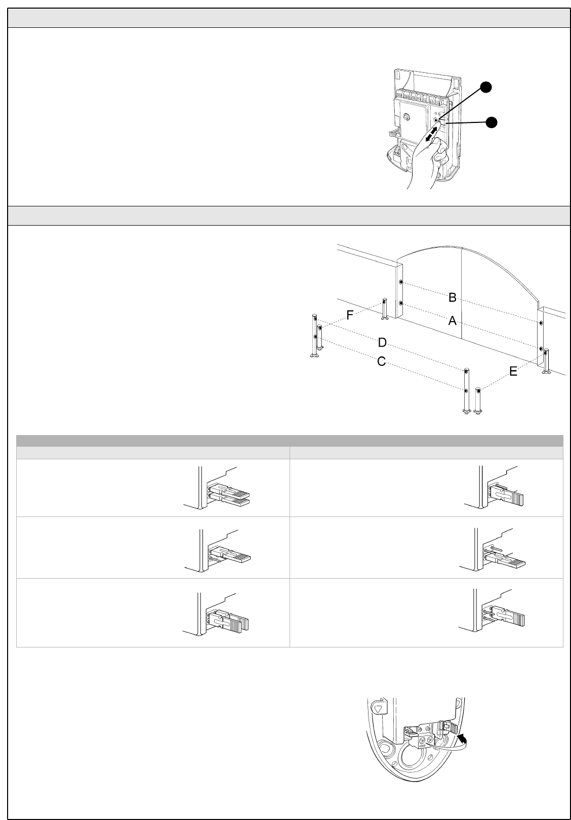
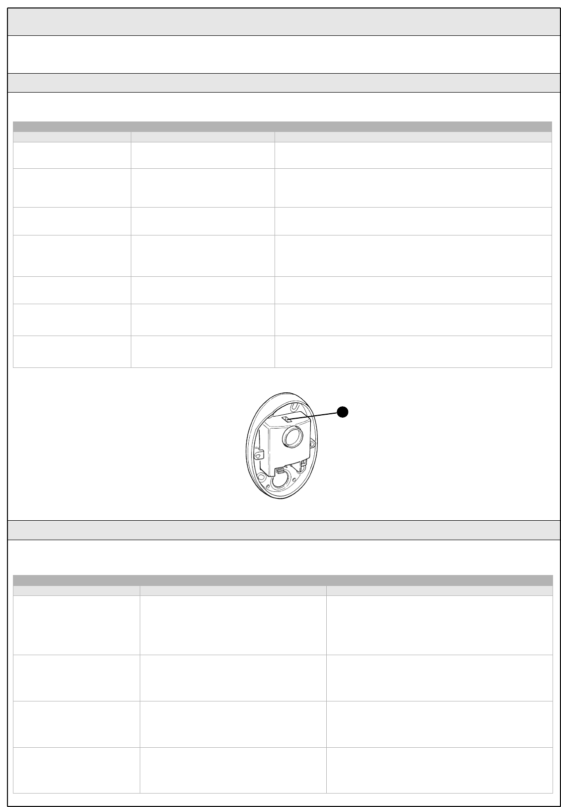
5.3.4 Addition of Optional Photocells
Additional photocells can be installed at any time on top of those
supplied with WG20. In an automation system for 2-leaf gates these can
be arranged as shown in Figure 64.
To ensure the correct recognition of the photocells by the control unit, the
former must be assigned addresses by means of jumpers. The address
allocation procedure must be performed on TX as well as RX (arranging the
jumpers in the same manner), but you must make sure that there are no other
pairs of photocells having the same address.
The photocells need to be assigned addresses to make sure that they are
correctly recognized among the other ECSBus devices, and in order to
assign the performed function.
1 Open the shell of the photocell.
2 Identify the position where they are installed based on figure 64 and
connect with jumper according to Table 11.
The unused jumpers must be stored in their proper compartment for
future use (Figure 65).
3 Perform the recognition stage as explained in paragraph 5.3.3
"Recognition of other devices".
Figure 64
Table 11
Photocell h=50cm;
activated when gate
closes
A
Photocell h=100cm;
activated when gate closes
B
CPhotocell h=50cm;
activated when gate opens
or closes
Photocell h=100cm; activated
when gate opens or closes
D
Photocell to the right
activated when gate opens
Photocell to the left
activated when gate opens
F
Photocell Jumpers Jumpers
Photocell
E
Figure 65
22 WG20 Instructions
The CL20 control unit contains a radio receiver for TX4 transmitters;
those included in the package are pre-memorized and operative.
If you wish to memorize a new radio transmitter you have two choices:
• Mode 1: in this "mode" the radio transmitter is used to its fullest extent,
i.e. all the buttons execute a pre-established command (the transmitters
supplied with WG20 are memorized in Mode 1). It is obvious that in
Mode 1 a radio transmitter can be used to command a single
automation, i.e.:
• Mode 2: one of the four commands available can be associated to
each button. This mode, used properly, allows you to command 2 or
more different automations; for example:
Each transmitter is, of course, a separate unit, and while some are
memorized in mode 1 others can be memorized in mode 2 on the
control unit.
The overall memory capacity is 150 units; memorization in mode 1 takes up
one unit for each transmitter while mode 2 takes up one unit for each button.
Warning: since the memorization procedures are timed (10s), you
must read the instructions in the following paragraph before you
proceed with their execution.
T1 button "OPEN" command
T2 button "Pedestrian gate" command
T3 button "Open only" command
T4 button "Close only" command
5.4 Memorization of Radio Transmitters
5.4.1 Memorization Mode 1
1 Press button P1 [B] for at least 3 s.. When the P1 LED [A] goes off,
release the button.
2 Within 10s, press any button on the radio transmitter to be memorized
and hold it down for at least 3s.
If the memorization procedure is successful, the "P1" LED will flash 3
times.
3 If there are other transmitters to be memorized, repeat step 2 within
the next 10s, otherwise the memorization stage will terminate
automatically.
Figure 66
5.4.2 Memorization Mode 2
With the memorization in mode 2 of the radio transmitter, any one of the
four commands ("OPEN", "Open partially", "Open only" and "Close only")
can be associated to each button.
In Mode 2 each button requires a separate memorization stage.
1 Delete the remote control system by following procedure "5.4.4
Deleting a radio transmitter."
2 Press button P1 (figure 66) on the control unit as many times as the
number corresponding to the desired command, according to the
following table: (e.g. 3 times for the "Open only" command).
3 Make sure that the P1 LED makes as many quick flashes as the
number corresponding to the selected command.
4 Within 10 s, press the desired button on the radio transmitter to be
memorized, and hold it down for at least 2 s.
If the memorization procedure is successful, the "P1" LED will flash 3
times slowly.
5 If there are other transmitters to be memorized for the same type of
command, repeat step 3 within the next 10s, otherwise the
memorization stage will terminate automatically.
1 time "OPEN" command
2 times "Pedestrian gate" command
3 times "Open only" command
4 times "Close only" command
B
A
T1 button "Open only" command
Tasto T2 "Close only" command
Tasto T3 "OPEN" command
Tasto T4 "OPEN" command
A new radio transmitter can be memorized in the control unit without
directly operating the buttons on it. You need to have an "OLD" pre-
memorized operational radio transmitter. The "NEW" radio transmitter to
be memorized will inherit the characteristics of the OLD one, i.e. if the
OLD radio transmitter was memorized in Mode 1, the NEW one will also
be memorized in Mode 1. In this case, during the memorization stage
you can press any key on the two transmitters. If, on the other hand, the
OLD transmitter was memorized in Mode 2 you must press the button
on the OLD transmitter which corresponds to the desired command,
and the button on the NEW transmitter to which you wish to associate
that command.
Holding the two transmitters, position yourself within the operating range
of the automation and perform the following operations:
1 Press the button on the NEW radio transmitter and hold it down for at
least 5s, then release it.
2 Press the button on the OLD radio transmitter 3 times slowly.
3 Press the button on the NEW radio transmitter once slowly.
At this point the NEW radio transmitter will be recognized by the control
unit and will assume the characteristics of the OLD one.
If there are other transmitters to be memorized, repeat all the steps
above for each new transmitter.
5.4.3 "Remote" Memorization
WG20 Instructions 23
5.4.5 Deleting all the Radio Transmitters
With this operation all the memorized transmitters are deleted.
1 Press the P1 button [B] on the control unit and hold it down.
2 Wait until the P1 LED [A] lights up, then wait until it goes off, than wait
until it has flashed 3 times.
3 Release the P1 button precisely upon the third flash.
4 Wait approximately 4s for the deletion process to be completed; during
this time the LED will flash very quickly.
If the procedure is successful, after a few moments the "P1" LED will
flash slowly 5 times. Figure 67
B
A
5.5 Troubleshooting
The following table contains instructions to help you solve malfunctions or errors that may occur during the installation stage or in case of failure.
Table 12
Symptoms Probable cause and possible solution
The radio transmitter does not emit any
signal (the LED [A] does not light up) • Check to see if the batteries are exhausted, if necessary replace them (page 34)
The manoeuvre does not start and the
"ECSBbus" LED [B] does not flash
• Make sure that the power cord is properly plugged into the mains outlet
• Check to see if the fuses [E] or [F] are blown; if necessary, identify the reason for the failure and then replace
the fuses with others having the same current rating and characteristics..
The manoeuvre does not start and the
flashing light is off
• Make sure that the command is actually received. If the command reaches the OPEN input, the
corresponding "OPEN" LED [D] must light up; if you are using the radio transmitter, the "ECSBus" LED must
make two long flashes.
The manoeuvre does not start and the
flashing light flashes a few times
• Make sure that the STOP input is active, i.e. that the "STOP" LED [C] comes on. If this does not happen,
check the devices connected to the STOP input.·
• The photocell test which is performed at the starting of each manoeuvre is not successful; check the
photocells, also according to Table 13 on page 24.
The manoeuvre starts but it is immediately
followed by a reverse run
• The selected force is too low to move the leaves. Check to see whether there are any obstacles; if
necessary increase the force as described on page 19.
The manoeuvre is carried out but the
flashing light does not work
• Make sure that there is voltage on the flashing light's FLASH terminal during the manoeuvre (being
intermittent, the voltage value is not important: approximately 10-30Vac); if there is voltage, the problem is
due to the lamp; in this case replace the lamp with one having the same characteristics.
E
A
CB D
F
Figure 68
5.4.4 Deleting a Radio Transmitter
If a radio transmitter is available, this operation allows you to delete it.
If the transmitter is memorized in Mode 1, a single deletion stage is
sufficient: just press any button at point 3. If the transmitter is memorized
in Mode 2, one deletion stage is needed for each memorized button.
1 Press and hold down button P1 [B] (Figure 67) on the control unit.
2 Wait until the P1 LED [A] lights up, then, within three seconds:
3 Press and hold down for at least three seconds the button of the radio
transmitter to be deleted.If the radio transmitter has been deleted, the P1
LED will flash quickly five times. If the LED flashes slowly just once, it
means that the deletion has not taken place because the transmitter is
not memorized
4 If there are more transmitters to be deleted, repeat step 3 within ten
seconds while pressing button P1, otherwise the deletion stage will
terminate automatically.
24 WG20 Instructions
5.6 Diagnostics and Signals
A few devices issue special signals that allow you to recognize the operating status or possible malfunctions.
Table 13
"SAFE" LED Status Action
Off The photocell is not powered or is
faulty
Make sure that there is voltage (approx. 8-12 Vdc) on the photocell's
terminals; if the voltage is correct, the photocell is probably faulty.
3 quick flashes and a
second's pause
Device not recognized by the control
unit
Repeat the recognition procedure on the control unit. Make sure that all the
photocell pairs on ECSBus have different addresses (see Table 11 on page
21)
1 very slow flash The RX receives a perfect signal Normal operation
1 slow flash The RX receives a fair signal Normal operation
1 quick flash The RX receives a poor signal Normal operation but you should check the TX-RX alignment and make sure
the glasses are clean
1 very quick flash The RX receives a very poor signal It is at the limit of normal operation, you should check the TX-RX alignment
and make sure the glasses are clean
Always on The RX does not receive any signal Check to see if there is an obstacle between TX and RX. Make sure that the
LED on TX flashes once slowly. Check the TX-RX alignment
Figure 69
A
5.6.1 Photocells
The photocells are equipped with a "SAFE" LED [A] that allows you to check the operating status at any time.
During the manoeuvre the flashing light flashes once every second. When something is wrong the flashes are more frequent (half a second); the light
flashes twice with a second's pause between flashes.
Table 14
Quick flashes Status Action
1 flash
1 second's pause
1 flash
ECSBus error
At the staring of the manoeuvre, the devices present do not
correspond to those recognized; check and if necessary try
repeating the recognition process. (see 5.3.3 "Recognition of
Other Devices").
One or more devices may be faulty; check and, if necessary,
replace them.
2 flash
1 second's pause
2 flashes
Triggering of a photocell
At the staring of the manoeuvre, one or more photocells do not
enable it; check to see if there are any obstacles. If there is an
obstacle impeding the movement no action is required.
3 flash
1 second's pause
3 flashes
Cutting in of the "motor force" limiting device During the movement, the leaf experienced excessive friction;
identify the cause
4 flash
1 second's pause
4 flashes
Cutting in of the STOP input During the movement the STOP input was activated; identify
the cause
5.6.2 Flashing light
WG20 Instructions 25
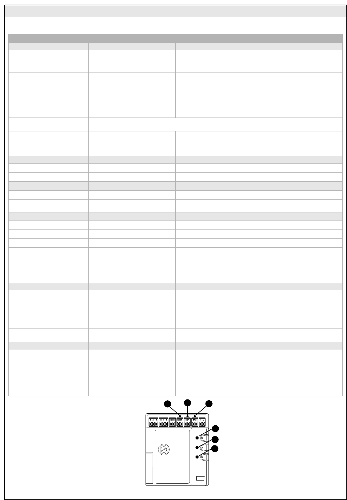
On the control unit there is a set of LED's each of which can give special indications both during normal operation and in case of malfunctions.
Figure 70
5.6.3 Control Unit
D
E
F
C
B
A
Table 15
ECSBus LED [A] Status Action
Off Malfunction
Make sure there is power supply; check to see if there are blown fuses;
identify the cause of the malfunction and then replace blown fuses with
others having the same characteristics
On Serious malfunction
There is a serious malfunction; try switching off the control unit for a few
seconds; if the condition persists it means there is a malfunction and the
electronic board has to be replaced
One flash every second Everything OK Normal operation of control unit
2 long flashes The status of the inputs has changed This is normal when there is a change in one of the inputs: OPEN, STOP,
triggering of photocells or the radio transmitter is used
Series of flashes separated by a
pause It corresponds to the flashing light's signal. See Table 14
Quick flash Short circuit on ECSBus
An overload has been detected and therefore the power supply to the
ECSbus has been interrupted. Check by disconnecting the devices one by
one, if necessary.To restore the power supply to the ECSBus just give the
command using the radio transmitter, for example.
STOP LED [B] Status Action
Off Cutting in of the STOP input Check the devices connected to the STOP input
On Everything OK STOP input active
OPEN LED [C] Status Action
Off Everything OK OPEN input not active
On Cuttin in of the OPEN input This is normal only if the device connected to the OPEN input is actually
active
P1 LED [D] Status Action
Off Everything OK No memorization in progress
On Memorization in Mode 1 This is normal during memorization in Mode 1 which lasts maximum 10s
Series of quick flashes, from 1 to 4 Memorization in Mode 2 This is normal during memorization in Mode 2 which lasts maximum 10s
5 quick flashes Deletion OK Deletion of one transmitter successful.
1 slow flash Wrong command A command from a non-memorized transmitter has been received
3 slow flashes Memorization OK Memorization process successful.
5 slow flashes Deletion OK Deletion of all transmitters successful.
P2 LED [E] Status Action
Off Everything OK “Slow" speed selected
On Everything OK “Fast" speed selected
1 flash every second
No device has been memorized or an
error has occurred during the
recognition process
There may be faulty devices; check and, if necessary, try repeating the
recognition process (see paragraph 3.5.1 "Learning of Connected Devices")
2 flashes per second Device recognition stage in progress It indicates that the search for the connected devices is under way (this
stage lasts a few seconds at the most)
P3 LED [F ] Status Action
Off Everything OK Single cyclic operation
On Everything OK Complete cyclic operation
1 flash every second No opening angle has been
memorized
Carry out the recognition stage (see paragraph "3.5.2 recognition of Leaves'
Opening and Closing Angles")
2 flashes every second Recognitionof opening angles in
progress It indicates that the recognition of the opening angles is under way
26 WG20 Instructions
6 Technical characteristics
WG20 is produced by NICE S.p.a. (TV) I, MHOUSE S.r.l. is an affiliate of the Nice S.p.a group.
Nice S.p.a., in order to improve its products, reserves the right to modify their technical characteristics at any time without prior notice. In any case,
the manufacturer guarantees their functionality and fitness for the intended purposes.
Note: all characteristics refer to a temperature of 20°C.
WG10 gearmotor for swing-leaf gate
Type Electromechanical gearmotor for automated gates and doors
Adopted technology 24Vdc motor, helical teeth reduction gear; mechanical release
Peak thrust 1800N
Nominal thrust 1200N
Idling speed 13 mm/s in "slow" speed mode; 24 mm/s in "fast" speed mode
Nominal torque speed 9 mm/s in "slow" speed mode; 16 mm/s in "fast" speed mode
Stroke 480 mm
Maximum frequency of cycles 60 complete cycles per day (the CL20 control unit allows up to a maximum of 10 cycles per hour)
Maximum continuous cycle time approx. 4 minutes
Working limits Its structural characteristics make it suitable for use on gates weighing up to 400Kg or leaves up to 4,5m
wide and with opening angle up to 130°
Power supply 24Vdc for "slow" speed and 36V dc for "fast" speed
Nominal input power 2,3A; the peak current is 3,2A for maximum 3s; equivalent to a peak power of 60W (*90W) and 90W (*120W).
(* "fast" speed values)
Operating ambient temperature -20 ÷50°C (the efficiency of the gearmotor decreases at low temperatures)
Suitable for use in acid, saline or
potentially explosive atmosphere No
Mounting Horizontal using the special mounting brackets.
Protection class IP44
Dimensions / weight 908 x 100 h 117/ 10kg
PH1 Photocells
Type Presence detector for automated gates and doors (type D according to EN 12453 standard) consisting of
a "TX" transmitter and an "RX" receiver
Adopted technology Optical, by means of direct TX-RX interpolation with modulated infrared ray
Detection capacity Opaque objects located on the optical axis between TX and RX, larger than 50mm and moving slower than
1.6m/s
TX transmission angle Approx. 20°
RX reception angle Approx. 20°
Useful capacity Up to 10m for maximum TX-RX misalignment of ± 5° (the device can signal an obstacle even in the case of
adverse weather conditions)
Power supply/output The device can be connected only to "ECSBus" networks from which it receives the power supply and
sends the output signals.
Absorbed power 1 ECSBus unit
Maximum cable length Up to 20 m (observe the directions regarding the minimum gauge and type of cable)
Addressing possibility Up to 7 detectors with protection function and 2 with opening command function. The automatic
synchronism prevents any interference among the various detectors
Operating ambient temperature -20 ÷50°C
Suitable for use in acid, saline or
potentially explosive atmosphere No
Mounting Vertical, wall-mounted
Protection class IP44
Dimensions / weight (TX and RX) 95 x 65 h 25mm / 65g

Power supply CL20/V1 120 Vac (+10% -15%) 50/60Hz
Maximum continuous cycle time 4 minutes
WG20 Instructions 27
CL20 Control Unit
Type Control unit for 1 or 2 24Vdc motors for gate or door automation, equipped with radio receiver for "TX4"
transmitters.
Adopted technology
Electronic board governed by 8-Bit microcontroller in flash technology. A transformer located in the control
unit but separated from the board reduces the mains voltage to the 24V rating used throughout the
automation system
Maximum frequency of cycles 60 complete cycles per day
(For a maximum of approx. 10 cycles per hour. A maximum of 2 cycles per hour is permitted at 50°C.)
Power supply CL20 230Vac (+10% -15%) 50/60Hz
Max. absorbed power 380W
Emergency power supply Designed to accommodate "PR1" buffer batteries
Motor outputs 2, for 24Vdc motors with 2,3A rated current, maximum peak current is 3.2A for maximum 3s (with "fast"
speed the motors' output voltage is 36Vdc)
Flashing light output For visual signalling devices with 12V lamp, maximum 21W
ECSBus output One output with a maximum load of 15 ECSBus units
"OPEN" input For normally open contacts (the closing of the contact causes the "OPEN" command)
"STOP" input For normally open contacts and/or for 8.2Kohm constant resistance, or normally closed contacts with
recognition of the "normal" status (any variation from the memorized status causes the "STOP" command)
Radio aerial input 52 ohm for RG58 or similar type of cable
Maximum cable length Mains power supply: 30m; motor outputs: 10m; other inputs/outputs: 20m with aerial cable preferably
shorter than 5m (observe the directions regarding the minimum gauge and type of cable)
Operating ambient temperature -20 ÷ 50°C
Suitable for use in acid, saline or
potentially explosive atmosphere No
Mounting Vertical, wall mounted
Protection class IP44
Dimensions / weight 180 x 240 h 110mm / 3100 g
Remote control possibility With "TX4" transmitters the control unit can receive one or more of the following commands: "OPEN",
"Open partially", "Open only" and "Close only"
TX4 transmitters memorized Up to 150 if memorized in mode 1
Range of TX4 transmitters from 50 to 100m. The range can vary if there are obstacles or electromagnetic disturbances, and is
affected by the position of the receiving aerial incorporated in the flashing light
Programmable Functions
"Cycle" or "Complete cycle" operation (automatic closing) "Slow" or "fast" motor speed
The pause time in the "complete cycle" mode can be set at 10, 20, 40, 80 seconds
The type of pedestrian opening can be selected from 4 modes
The sensitivity of the obstacle detection system can be selected from 4 levels
The operation of the "Open" command can be selected from 4 modes
Self-programmed functions
Automatic detection of devices connected to the ECSBus output
Automatic detection of the type of "STOP" device (NO or NC contact or 8.2KΩconstant resistance)
Automatic detection of the manoeuvring length for each motor
Automatic detection of automation with 1 or 2 motors
KS1 Key-Operated Selector Switch
Type Key-operated double switch suitable for control of automatic gates and doors. Illuminated for night
operation.
Adopted technology
Activation protected by a lock, the insertion and clockwise turning of the key causes the closing of a
contact , the counter-clockwise turning of the key causes the closing of the second contact; spring-loaded
for return of key to the middle position.
Tamper-proof The selector switch can be opened to access the connections only by inserting the key and turning it in
either direction
Security lock Key with 450 different key numbers
Power supply/contacts The device can only be connected to the "OPEN" and "STOP" terminals on the MHOUSE gate automation
control units, to which it sends the control signals and by which it is energized for night illumination
Operating ambient temperature -20 ÷ 50°C
Suitable for use in acid, saline or
potentially explosive atmosphere No
Mounting Vertical, wall mounted
Protection class IP44
Dimensions / weight 95 x 65 h 36mm / 135g
28 WG20 Instructions
FL1 Flashing light
Type Flashing signalling light for automatic gates and doors. The device incorporates a receiving aerial for
remote control
Adopted technology Visual signalling device with 12V 21W lamp, controlled by MHOUSE automation control units
Lamp 12V 21W BA15 socket (automotive type lamp)
Power supply The device can be connected only to the "FLASH" and "AERIAL" terminals on the MHOUSE automatic
gate control units
Operating ambient temperature -20 ÷ 50°C
Not suitable for use in acid, saline or
potentially explosive atmosphere No
Mounting Horizontal surface-mounted or vertical wall-mounted
Protection class IP44
Dimensions / weight 120 x 60 h 170mm / 285g
TX4 transmitters
Type Radio transmitters for remote control of automatic gates and doors
Adopted technology AM OOK coded modulation of radio carrier
Frequency 433.92 Mhz
Coding Rolling code with 64 Bit code (18 billion million combinations)
Buttons 4, each button can be used for the different controls of the same control unit or to control different control
units.
Irradiated power approx. 0.0001W
Power supply 6V +20% -40% with two CR2016 type lithium batteries
Battery life 3 years, estimated on the basis of 10 commands/day, each lasting 1s at 20°C (at low temperatures the
efficiency of the batteries decreases)
Operating ambient temperature -20 ÷ 50°C
Not suitable for use in acid, saline or
potentially explosive atmosphere No
Protection class IP40 (suitable for use indoors or in protected environments)
Dimensions / weight 72 x 31 h 11mm / 18g
7 Annexes
CE Declaration of Conformity to be filled in and delivered to the owner of the power operated gate.
7.2 Annexe 2: CE Declaration of Conformity of Power Operated Gate
7.3 Annexe 3: Operating Guide
7.1 Annexe 1: CE Declaration of Conformity of WG20 Components
CE Declaration of Conformity of WG20 components; this statement must be attached to the technical documentation.
The following annexes are designed to help you prepare the technical documentation.
Brief guide to be used as an example for drafting the operating guide to be delivered to the owner of the power operated gate.
Declaration of conformity
EC Declaration of Conformity with Directives 98/37/EC, 73/23/EEC, 89/336/EEC and 1999/5/EC
WG20 is produced by NICE S.p.a. (TV) I; MHOUSE S.r.l. is an affiliate of the Nice S.p.a. group.
Number: 214/WG20/GB Date: 02/02/2005 Revision: 1
The undersigned Lauro Buoro, in his capacity as Managing Director, declares under his sole responsibility that the following product:
Manufacturer's name: NICE s.p.a.
Address: Via Pezza Alta 13, 31046 Z.I. Rustignè, Oderzo (TV) Italy
Model: WG10, CL20, TX4, PH1, KS1, FL1
Is in conformity with the provisions and specifications of the following European Directives:
Oderzo, 2 February 2005 Lauro Buoro
(Managing Director)
Reference Heading
98/37/CE
(modified 89/392/EEC)
DIRECTIVE 98/37/EC OF THE EUROPEAN PARLIAMENT AND OF THE COUNCIL of June 22, 1998, for the harmoni-
sation of the legislations of member States regarding machines.
According to Annexe II, part B (EC declaration of conformity by the manufacturer)
According to the following harmonised standards: EN 60335-1.
According to the following harmonised standards: EN 61000-6-2; EN 61000-6-3.
Reference Heading
1999/5/EC DIRECTIVE 1999/5/EC OF THE EUROPEAN PARLIAMENT AND OF THE COUNCIL of 9th March 1999 concerning
radio equipment and telecommunications terminal equipment and mutual recognition of their conformity.
According to the following standards: ETSI EN 300 220-3; ETSI EN 301 489-1; ETSI EN 301 498-3.
Reference Heading
73/23/EEC DIRECTIVE 73/23/EEC OF THE EUROPEAN COUNCIL of 19th February 1973 for the harmonization of the legislation
of member States regarding electrical equipment designed to be used within certain voltage limits.
89/336/EEC DIRECTIVE 89/336/EEC OF THE EUROPEAN COUNCIL of 3rd May 1989, for the harmonization of the legislations of
member States regarding electromagnetic compatibility.
As specified in the 98/37EC directive, the use of this product is not admitted until the machine, on which this product is mounted, has been identified
and declared as conforming to the directive 98/37/CE.
Satisfies the essential requirements of the following Directives, as amended by the directive 93/68/EEC of the European Council of 22nd July 1993:
Furthermore, the product complies with the essential requisites specified in article 3 of the following EC directive, for the use the products have been manufactured for:


According to Directive 98/37/EC, ANNEXE II, part A (CE declaration of conformity for machines)
The undersigned / Company
(name or business name of person who has put the power operated gate into service )
(address)
Declares under his/her sole responsibility that:
The automation : power operated gate with swing leaves
Serial number :
Year of manufacture :
Location (address) :
Satisfies the essential requirements of the following Directives:
98/37/EC Machine Directive
89/336/EEC Electromagnetic Compatibility Directive
73/23/EEC Low Voltage Directive
99/5/EC "R&TTE" Directive
and the provisions of the following harmonised standards:
EN 12445 "Industrial, commercial and garage doors and gates. Safety in use of
power operated doors - Test methods"
EN 12453 "Industrial, commercial and garage doors and gates. Safety in use of
power operated doors - Requirements"
Name Signature
Date Location
Declaration of conformity

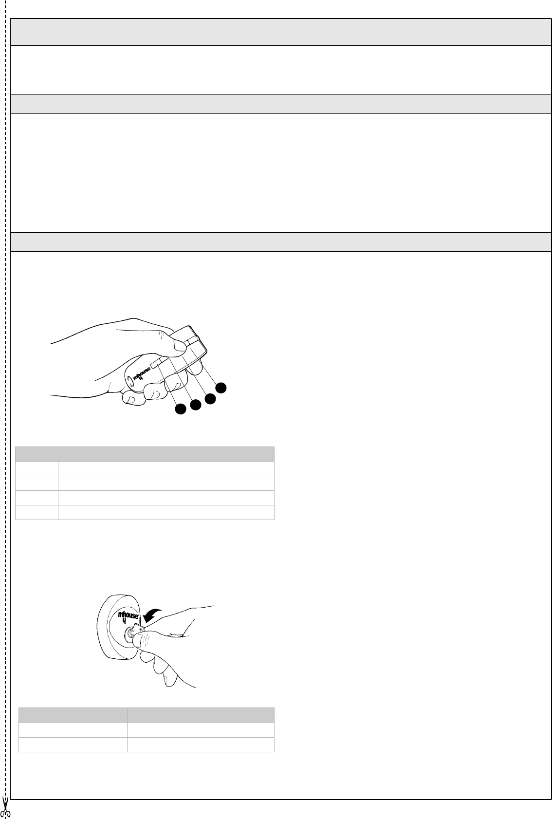
WG20 Instructions 33
• Keep at a safe distance while the gate is moving; do not pass
through until the gate has opened all the way and the leaves have
stopped moving.
• Do not allow children to play near the gate or with its controls.
• Stop using the automation system immediately if you notice
anything abnormal (strange noise or jerky movements); failure to
observe this warning may result in serious danger and accidents.
• Do not touch any components while they are moving.
• Have periodic checks made according to the instructions
provided in the maintenance schedule.
• Maintenance operations and repairs can only be performed
by qualified technicians.
This guide should be stored in an accessible location and made available
to all users of the automation.
7.3 Annexe 3: Operating Guide
7.3.1 Safety regulations
With radio transmitter
The radio transmitter is ready for use and the four buttons have the
following functions:
With selector switch
The selector switch has two positions, with automatic return to the centre.
Control with safety devices out of order
If the safety devices are out of order or malfunctioning, it is still possible
to control the gate.
1 Operate the gate control device (remote control or key-operated
selector switch). If the safety devices enable the operation, the gate will
open normally, otherwise:
2 The flashing light flashes a few times but the manoeuvre does not start
(the number of flashes depends on the reason why the manoeuvre is not
enabled).
3 In this case, actuate the control again within 3 seconds and keep it
actuated.
4 After approximately 2s the gate will start moving in the "man present"
mode, i.e. so long as the control is maintained the gate will keep moving;
as soon as the control is released the gate will stop.
If the safety devices are out of order the automation must be repaired as
soon as possible.
FUNCTION (*)
T1 button
T2 button
T3 button
T4 button
ACTION FUNCTION
Rotated to the right: "OPEN" (*)
Rotated to the left: "STOP" It stops the movement of the gate
(*) This item must be drafted by the person who has programmed the
system:.
Figure 71
Figure 72
7.3.2 Gate Control
(*) This table must be prepared by the person who has programmed the
system:
T1
T2
T3
T4
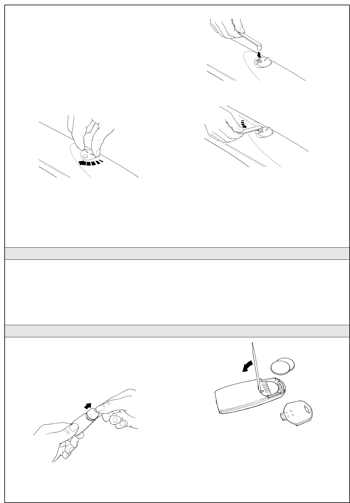
34 WG20 Instructions
Gearmotor release
The gearmotor is equipped with a mechanical system which allows the
gate to be opened and closed manually (i.e. as if WG20 were not present).
The manual operation must be resorted to in case o power failures or
system malfunctions. If a power failure occurs, the buffer battery can be
used (PR1 optional accessory).
If there is a malfunction of the gearmotor it is still possible to try and
release the motor in order to check whether the problem is connected
with the release mechanism.
1 Turn the release mechanism cover clockwise until the hole matches the
release pin.
2 Insert the key in the pin.
3 Turn the key anti-clockwise.
4 At this point, the gate leaf can be moved manually.
5 To restore the functionality of the automation system, rotate the lever
clockwise while simultaneously moving the leaf until it is caught by the
mechanism.
6 Remove the key and close the cover by turning it anti-clockwise.
The only maintenance operations that the user can and must perform
periodically concern the cleaning of the photocell glasses and the
removal of leaves and debris that may impede the automation.
• Use a slightly damp cloth (not wet) to clean the surface of the
devices. Do not use any substances containing alcohol, benzene,
diluents or other flammable substances. The use of these
substances could damage the devices, start fires or generate
electric shocks.
• Disconnect the power supply to the automation before you
proceed to remove leaves and debris, to prevent anyone from
activating the gate.
If the range of the remote control is significantly diminished and the light
emitted by the LED is feeble, the remote control battery is probably
exhausted. The remote control houses to CR2016 type lithium batteries.
To replace them proceed as follows:
1 Open the bottom by pulling it.
2 Insert a small pointed tool in the slit and prise the batteries out.
3 Insert the new battery, observing the polarity (the "+" symbol towards
the bottom ).
4 Close the bottom until it clicks.
The batteries contain polluting substances: do not dispose of
them together with other waste but use the methods established
by local regulations.
Figure 74
7.3.3 Maintenance Operations to Be Performed by the User
Figure 76
Figure 77
Figure 73
Figure 75
7.3.4 Replacing the Remote Control Battery


Mhouse
Via Pezza Alta, 13 - Z.I. Rustignè
31046 Oderzo TV Italia
Tel. +39 0422 20 21 09
Fax +39 0422 85 25 82
info@mhouse.biz
www.mhouse.biz