MINEW TECHNOLOGIES MS50SF3 BLE module User Manual
SHENZHEN MINEW TECHNOLOGIES CO., LTD. BLE module
UserManual.wiki
>
MINEW TECHNOLOGIES
>
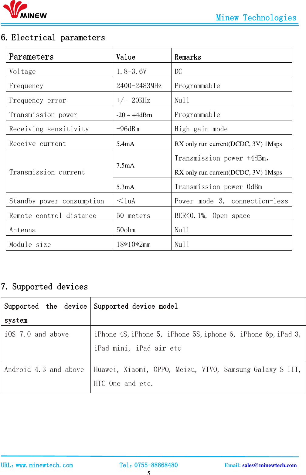
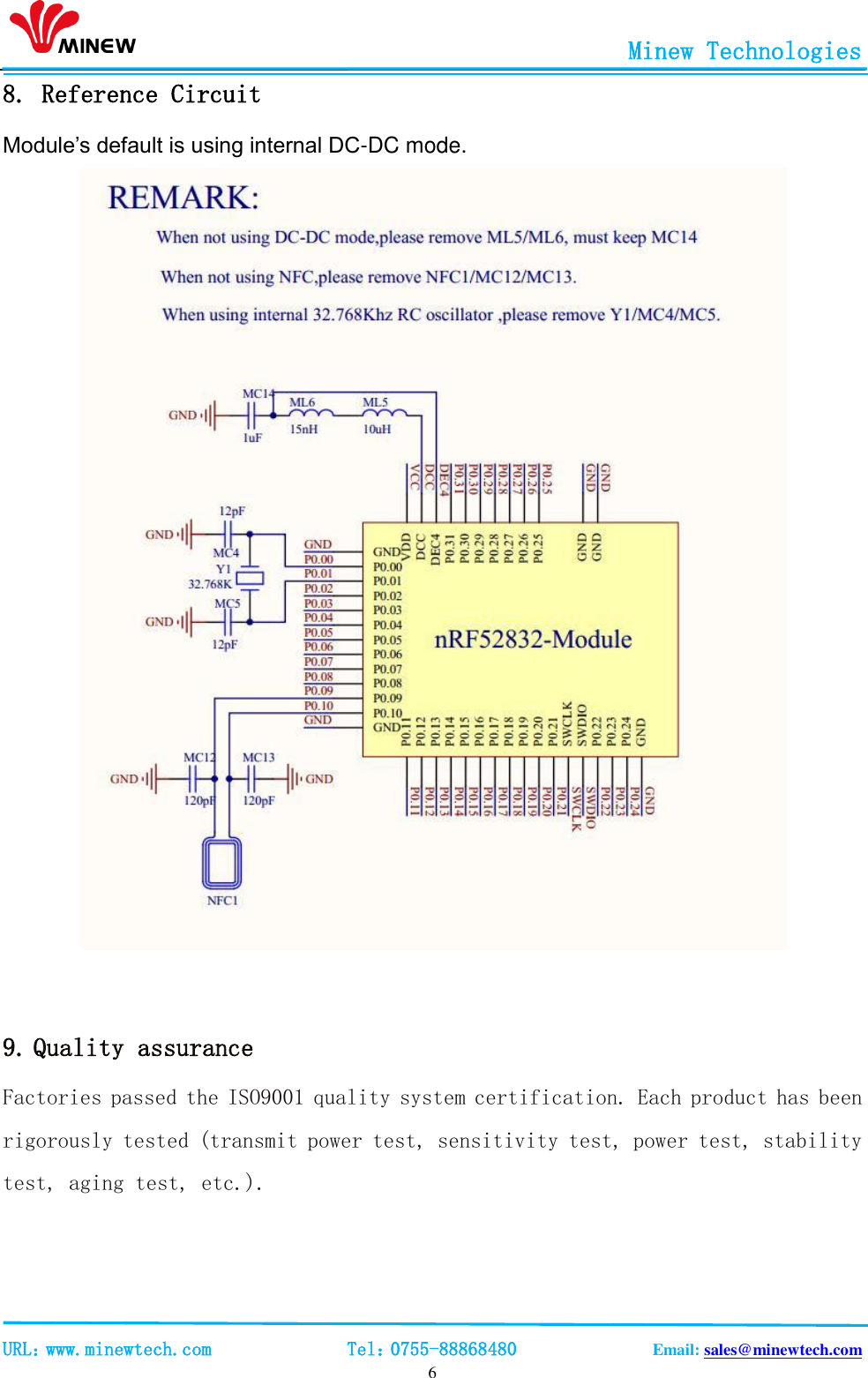
MS50SF3 User Manual
Manual
Navigation menu
Upload a User Manual
Namespaces
Wiki Guide
HTML
PDF
Info
Views
User Manual
Discussion / Help
Navigation