MIR Medical Research MIR009 Portable multipurpose and multifunction spirometer User Manual MANUALE SPIROLAB III REV0 EN
MIR Medical International Research Portable multipurpose and multifunction spirometer MANUALE SPIROLAB III REV0 EN
UserManual.wiki
>
MIR Medical Research
>
MIR009 User Manual
Manual
Navigation menu
Upload a User Manual
Namespaces
Wiki Guide
HTML
PDF
Info
Views
User Manual
Discussion / Help
Navigation

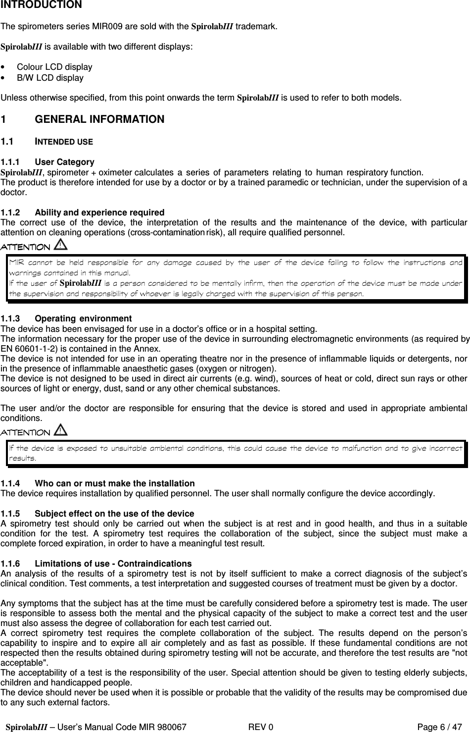
![SpirolabIII – User’s Manual Code MIR 980067 REV 0 Page 13 / 47 *PEF Best PEF L/s FVC Forced Vital Capacity L FEV1 Volume expired in the 1st second of the test L FEV1% FEV1/FVC x 100 % FEV1/VC% FEV1/VC x 100 % PEF Peak expiratory flow L/s FEF2575 Average flow between 25% and 75% of the FVC L/s FEF25 Forced Expiratory Flow at 25% of FVC L/s FEF50 Forced Expiratory Flow at 50% of FVC L/s FEF75 Forced Expiratory Flow at 75% of FVC L/s FEV6 Volume expired in the initial 6 seconds of the test L FEV6% FEV1/FEV6 x 100 % FET Forced expiratory time s VEXT Extrapolated volume mL FIVC Forced inspiratory volume L FIV1 Volume inspired in the 1st second of the test L FIV1% FIV 1 % % PIF Peak inspiratory flow L/s MVVcal Maximum voluntary ventilation calculated from the FEV1 L/s VC Slow vital capacity (expiratory) L IVC Slow inspiratory vital capacity L IC Inspiratory capacity L ERV Expiratory reserve volume L TV Current volume L VE Ventilation per minute, at rest L/min RR Respiratory frequency Breath/min tI Average time of inspiration, at rest s tE Average time of expiration, at rest s TV/tI Average flow of inspiration, at rest L/min tI/Ttot tE/(tI+tE) / MVV Maximum voluntary ventilation L/min *= best values 1.6.2 Features of the oximeter Measurement method: Red and infrared absorption Range of measurement %SpO2: 0 – 99% (with 1% increments) %SpO2 accuracy: ± 2% between 70-99% SpO2 Average number of heart beats for the %SpO2 calculation: 8 beats Range of measurement of cardiac pulse: 30 – 254 BPM (with 1 BPM increments) Accuracy of cardiac pulse: ± 2 BPM or 2% Average interval for the calculation of cardiac pulse: 8 seconds Signal quality indication: 0 - 8 segments on display Definitions: Desaturation Event Desaturation events SpO2 fall >= 4% in a limited period of 8-40 sec and successive rise > = 2% within a total period of 150 sec. Total Pulse rate Variation Pulse rate rise >= 10 BPM in limited period of 8-40 sec and successive fall >=8 BPM during a total period of 150 sec. Parameters measured during sleep oximetry: SYMBOL DESCRIPTION Units SpO2 Baseline SpO2 Average in first three minutes % SpO2 Min SpO2 Minimum during analysis period % SpO2 Max SpO2 Maximum during analysis period % SpO2 Mean SpO2 Average during analysis period % BPM Baseline Average pulse frequency in the first 3 minutes BPM BPM Min Minimum pulse frequency during the analysis period BPM BPM Max Maximum pulse frequency during the analysis period BPM BPM Mean Average pulse frequency during the analysis period BPM Recording time Total time measure of SpO2 hh:mm:ss T < 90% Time passed with SpO2 < 90 % % hh:mm:ss T < 89% Time passed with SpO2 < 89 % % hh:mm:ss T < 88% Time passed with SpO2 < 88 % % hh:mm:ss T < 87% Time passed with SpO2 < 87 % % hh:mm:ss N° Events SpO2 <89% Fall of SpO2 below 89% for at least 20 seconds \ ∆ Index [12s] Index of SpO2 fluctuation calculated in intervals of 12 sec. \](https://usermanual.wiki/MIR-Medical-Research/MIR009/User-Guide-685317-Page-13.png)
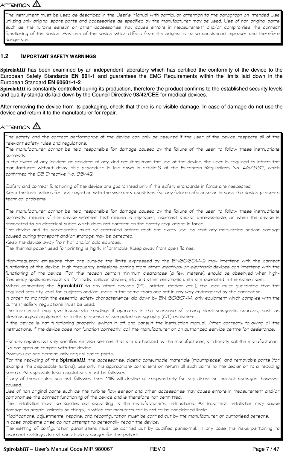
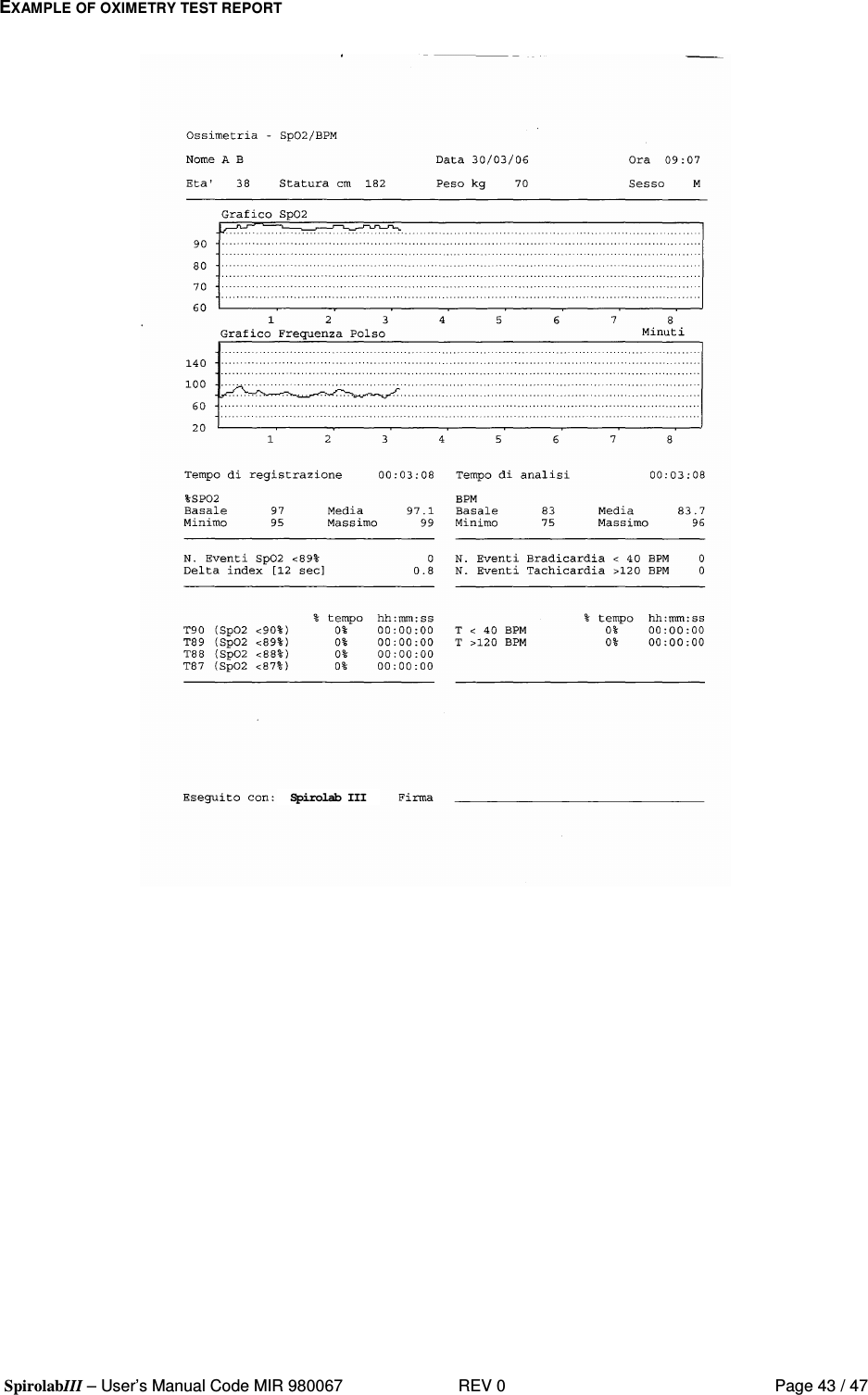
![SpirolabIII – User’s Manual Code MIR 980067 REV 0 Page 14 / 47 T< 40 BPM Time passed with pulse frequency < 40 BPM % hh:mm:ss T> 120 BPM Time passed with pulse frequency > 120 BPM % hh:mm:ss N° Events < 40 BPM Bradycardia events during the entire analysis period \ N° Events > 120 BPM Tachycardia events during the entire analysis period \ Tot. Desat. Events Desaturation events during the entire analysis period \ ODI Desaturation events per hour of analysis 1/h Mean Duration Average duration of desaturation events s Longest Duration Longest duration of desaturation events s Desaturation Peak Minimum Sp02 during desaturation events % Mean Desaturation Average duration of desaturation events % Mean Drop SpO2 Average SpO2 fall with respect to baseline, during the desaturation events % Max Drop SpO2 Maximum fall of SpO2 with respect of baseline, during the desaturation events % N° Pulse Variations Variation of pulse frequency events during the entire analysis period \ Pulse Index Variation of pulse frequency by hour of analysis 1/h NOD 4% Time passed with SpO2 < 4 % with respect to SpO2 base for continual periods above 5 minutes \ hh:mm:ss NOD 89% Time passed with SpO2 < 89 % for continued periods above 5 minutes \ hh:mm:ss NOD 90% Time passed with SpO2 < 90 % for continued periods above 5 minutes with minimum value < 86 % (Nadir) \ hh:mm:ss ∆=DELTA Parameters measured during walk test: SYMBOL DESCRIPTION Units SpO2 Baseline SpO2 average before walking % SpO2 End SpO2 after walking % SpO2 Min SpO2 minimum during walking % SpO2 Max SpO2 maximum during walking % SpO2 Mean SpO2 average during walking % BPM Vaseline Average pulse frequency before walking BPM BPM End Pulse frequency after walking BPM BPM Min Pulse frequency minimum during walking BPM BPM Max Pulse frequency maximum during walking BPM BPM Mean Pulse frequency average during walking BPM T < 90% Time passed with SpO2 < 90 % % hh:mm:ss T < 89% Time passed with SpO2 < 89 % % hh:mm:ss T < 88% Time passed with SpO2 < 88 % % hh:mm:ss T < 87% Time passed with SpO2 < 87 % % hh:mm:ss T∆2 [∆SpO2 2%] Time passed during walking test with SpO2 < 2 % with respect to SpO2 base hh:mm:ss T∆4 [∆SpO2 4%] Time passed during SpO2 walking test < 4 % with respect to SpO2 base hh:mm:ss T< 40 BPM Time passed with pulse frequency < 40 BPM hh:mm:ss T> 120 BPM Time passed with pulse frequency > 120 BPM hh:mm:ss N° Events < 40 BPM Bradycardia events during the entire period of analysis \ N° Events > 120 BPM Tachycardia events during the entire period of analysis \ Recording time Total time measure of SpO2 hh:mm:ss Baseline Time Duration of baseline phase hh:mm:ss Walking Time Duration of walking phase hh:mm:ss Recovery Time Duration of recovery phase hh:mm:ss Predicted Predicted standard distance m Pred. Min Predicted minimum distance m % Predicted Standard % in variations of the distance covered with respect to predicted standard distance % % Pred. Min % of variations of distance covered with respect to predicted minimum distance % AUC/Distance Area under SpO2 curve base relative to distance covered \ Dyspnea Borg CHG Variation in grade of dyspnea during walking \ Fatigue Borg CHG Variations in level of fatigue during walking \ ∆=DELTA * Here follows a description of the method for calculating the area below the SpO2 baseline curve:](https://usermanual.wiki/MIR-Medical-Research/MIR009/User-Guide-685317-Page-14.png)
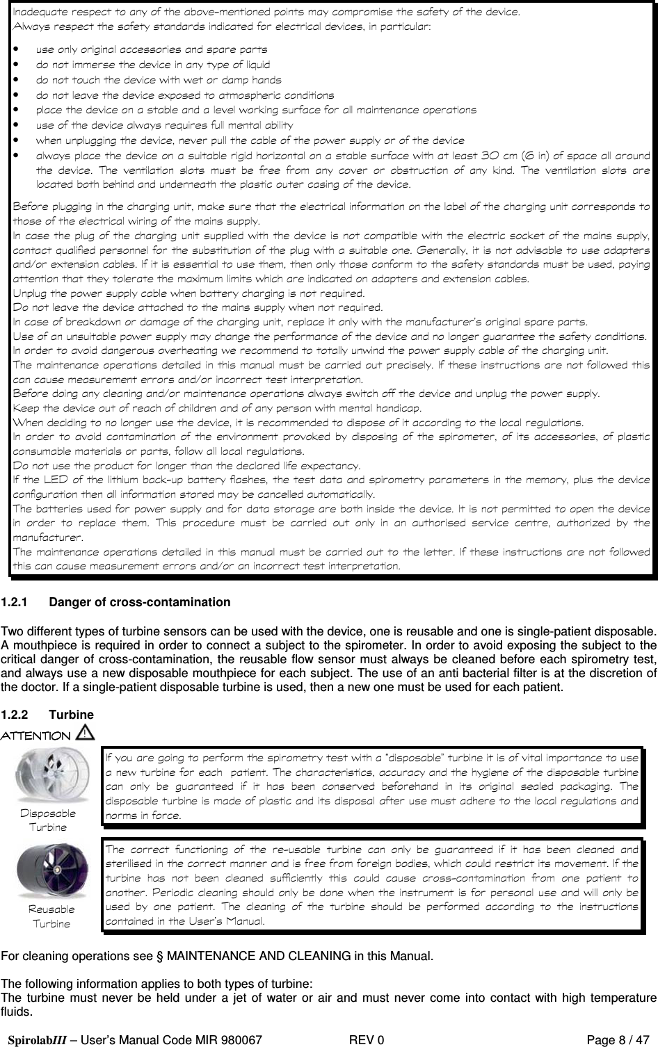
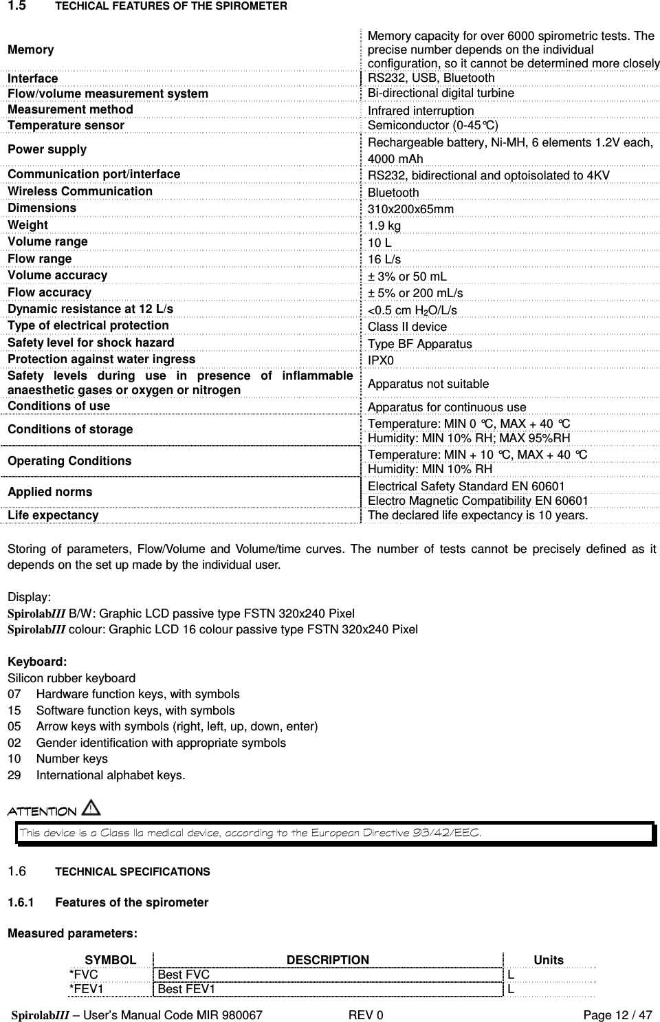
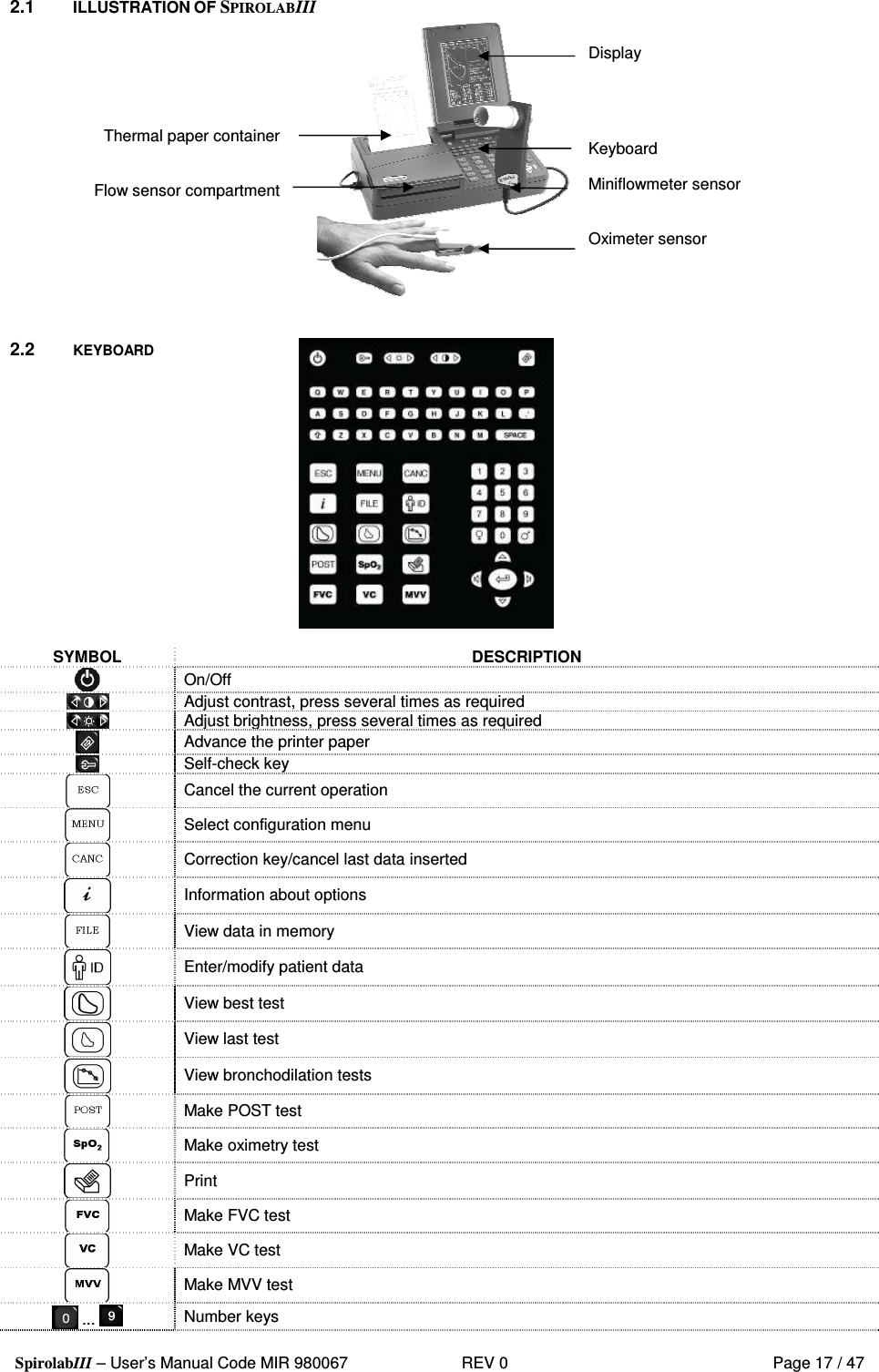
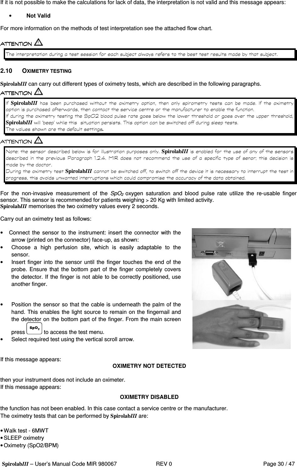
![SpirolabIII – User’s Manual Code MIR 980067 REV 0 Page 15 / 47 Parameters required for walk test: SYMBOL DESCRIPTION Units Dyspnea Borg Baseline Grade of dyspnea before walking \ Dyspnea Borg End Grade of dyspnea after walking \ Fatigue Borg Baseline Level of fatigue before walking \ Fatigue Borg End Level of fatigue after walking \ Walked Distance covered during walking m Parameters measured with SpO2 Analysis: SYMBOL DESCRIPTION Units SpO2 Baseline SpO2 Average in first three minutes % SpO2 Min SpO2 Minimum during analysis period % SpO2 Max SpO2 Maximum during analysis period % SpO2 Mean SpO2 Average during analysis period % BPM Baseline Average pulse frequency in the first 3 minutes BPM BPM Min Minimum pulse frequency during the analysis period BPM BPM Max Maximum pulse frequency during the analysis period BPM BPM Mean Average pulse frequency during the analysis period BPM Recording time Total time measure of SpO2 hh:mm:ss T < 90% Time passed with SpO2 < 90 % % hh:mm:ss T < 89% Time passed with SpO2 < 89 % % hh:mm:ss T < 88% Time passed with SpO2 < 88 % % hh:mm:ss T < 87% Time passed with SpO2 < 87 % % hh:mm:ss N° Events SpO2 < 89% Fall of SpO2 below 89 % for at least 20 seconds \ ∆ Index [12s] Index of SpO2 fluctuation calculated in intervals of 12 seconds \ T< 40 BPM Time passed with pulse frequency < 40 BPM % hh:mm:ss T> 120 BPM Time passed with pulse frequency > 120 BPM % hh:mm:ss N° Events < 40 BPM Bradycardia events during the entire analysis period \ N° Events > 120 BPM Tachycardia events during the entire analysis period \ ∆=DELTA Acoustic signals for oximetry: • Beep with frequency of the cardiac pulse • Continuous beep in the case of either %SpO2 or cardiac pulse going outside of the programmed alarm levels • Continuous beep during oximetry measurement in the case of low battery level The specifications for both the oximetry and for the cardiac pulse are the same, regardless of which of the above mentioned oximetry sensors is used. 2 PRODUCT DESCRIPTION SpirolabIII is a spirometer with an optional pulse oximetry module that facilitates the total valuation of lung function. It is a powerful and compact measurement device intended for use by a physician (respiratory specialist), and which is capable of calculating more than 30 spirometric parameters. SpirolabIII is able to make FVC, VC, IVC, MVV and breathing profile tests, as well as the saturation of oxygen in the blood and the heart beat. It can operate in stand alone mode, and it can be connected to a PC or to a printer using any one of several available methods: RS232, USB, Bluetooth. It calculates an index of test acceptability (test quality control) and a measure of reproducibility; It also gives functional interpretation with 11 possible levels following the latest ATS (American Thoracic Society) classification; it has an internal memory sufficient for over 6000 spirometry tests or for 1000 hours (or 40 days) of oximetry monitoring. The main spirometric parameters are measured and displayed and all data with Flow/Volume and Volume/time curves can be printed out in seconds by the built-in thermal printer. The Flow/Volume curve is shown in real time on the display.](https://usermanual.wiki/MIR-Medical-Research/MIR009/User-Guide-685317-Page-15.png)
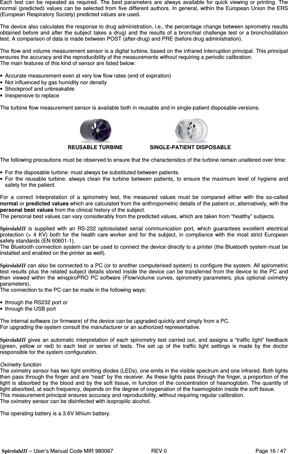

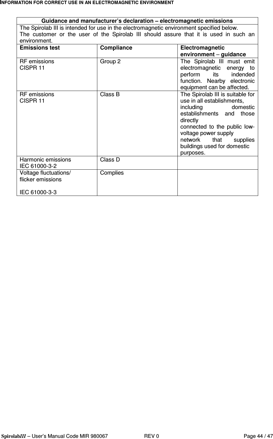
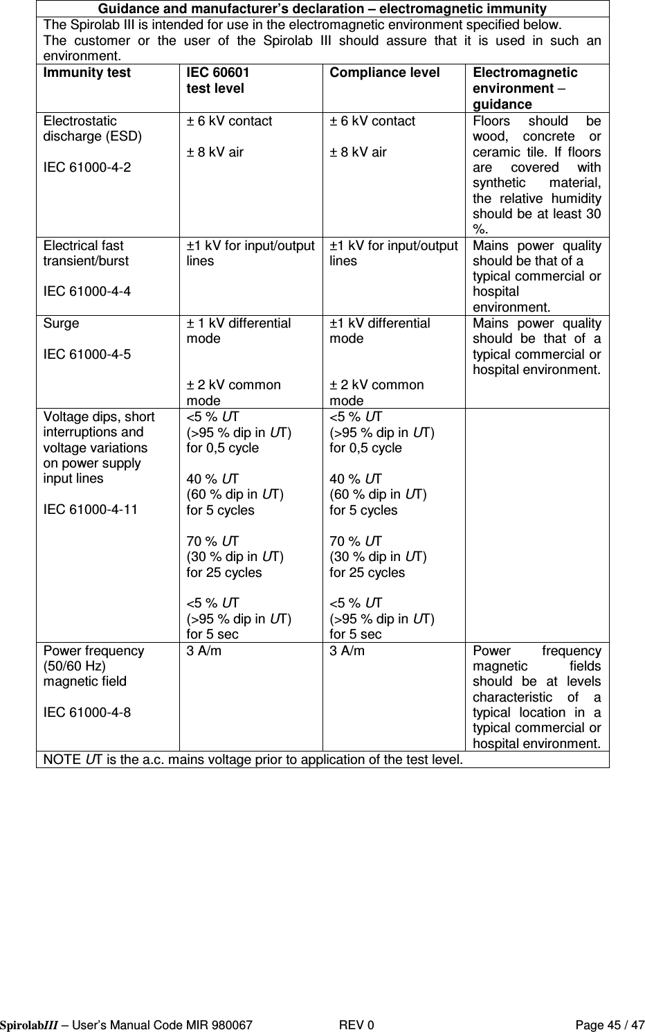
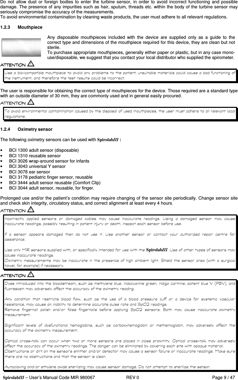
![SpirolabIII – User’s Manual Code MIR 980067 REV 0 Page 46 / 47 Guidance and manufacturer’s declaration – electromagnetic immunity The Spirolab III is intended for use in the electromagnetic environment specified below. The customer or the user of the Spirolab III should assure that it is used in such an environment. Immunity test IEC 60601 test level Compliance level Electromagnetic environment – guidance Conducted RF IEC 61000-4-6 Radiated RF IEC 61000-4-3 3 Vrms 150 kHz to 80 MHz 3 V/m 80 MHz to 2,5 GHz [3 ] V [3 ] V/m Portable and mobile RF communications equipment should be used no closer to any part of the Spirolab III, including cables, than the recommended separation distance calculated from the equation applicable to the frequency of the transmitter. Recommended separation distance d=[ 3.5 ] P 3 d=[ 3.5 ] P 80 MHz to 800 GHz 3 d=[ 7 ] P 800 MHz to 2,5 GHz 3 where P is the maximum output power rating of the transmitter in watts (W) according to the transmitter manufacturer and d is the recommended separation distance in metres (m). Field strengths from fixed RF transmitters, as determined by an electromagnetic site survey, should be less than the compliance level in each frequency range.b Interference may occur in the vicinity of equipment marked with the following symbol: NOTE 1 At 80 MHz and 800 MHz, the higher frequency range applies. NOTE 2 These guidelines may not apply in all situations. Electromagnetic propagation is affected by absorption and reflection from structures, objects and people. a Field strengths from fixed transmitters, such as base stations for radio (cellular/cordless) telephones and land mobile radios, amateur radio, AM and FM radio broadcast and TV broadcast cannot be predicted theoretically with accuracy. To assess the electromagnetic environment due to fixed RF transmitters, an electromagnetic site survey should be considered. If the measured field strength in the location in which the Spirolab III is used exceeds the applicable RF compliance level above, the Spirolab III should be observed to verify normal operation. If abnormal performance is observed, additional measures may be necessary, such as reorienting or relocating the Spirolab III. b Over the frequency range 150 kHz to 80 MHz, field strengths should be less than [3] V/m.](https://usermanual.wiki/MIR-Medical-Research/MIR009/User-Guide-685317-Page-46.png)
![SpirolabIII – User’s Manual Code MIR 980067 REV 0 Page 47 / 47 Recommended separation distances between portable and mobile RF communications equipment and the Spirloab III The Spirolab III is intended for use in an electromagnetic environment in which radiated RF disturbances are controlled. The customer or the user of the Spirolab III can help prevent electromagnetic interference by maintaining a minimum distance between portable and mobile RF communications equipment (transmitters) and the Spirolab III as recommended below, according to the maximum output power of the communications equipment. Separation distance according to frequency of transmitter m Rated maximum output power of transmitter W 150 kHz to 80 MHz d=[ 3.5 ] P V1 80 MHz to 800 MHz d=[ 3.5 ] P E1 800 MHz to 2,5 GHz d=[ 7 ] P E1 0.01 0.12 0.24 0.24 0.1 0.37 0.37 0.74 1 1.17 1.17 2.34 10 5.28 5.28 1.056 100 11.66 11.66 23.32 For transmitters rated at a maximum output power not listed above, the recommended separation distance d in metres (m) can be estimated using the equation applicable to the frequency of the transmitter, where P is the maximum output power rating of the transmitter in watts (W) according to the transmitter manufacturer. NOTE 1 At 80 MHz and 800 MHz, the separation distance for the higher frequency range applies. NOTE 2 These guidelines may not apply in all situations. Electromagnetic propagation is affected by absorption and reflection from structures, objects and people.](https://usermanual.wiki/MIR-Medical-Research/MIR009/User-Guide-685317-Page-47.png)