MIR Medical Research MIR009 Portable multipurpose and multifunction spirometer User Manual MANUALE SPIROLAB III REV0 EN
MIR Medical International Research Portable multipurpose and multifunction spirometer MANUALE SPIROLAB III REV0 EN
Manual

SpirolabIII – User’s Manual Code MIR 980067 REV 0 Page 1 / 47
Spirolab III
User’s Manual Rev.0
Issued on 21/06/06
Approved on 21/06/06
SpirolabIII – User’s Manual Code MIR 980067 REV 0 Page 2 / 47
Thank you for choosing a product from MIR
Medical International Research
The original packaging contains one of the following spirometers, complete with its standard accessories:
PRODUCT without oximetry option CODE PRODUCT with oximetry option CODE
SpirolabIII bag 672685 SpirolabIII bag 672685
SpirolabIII device 910551 SpirolabIII device plus oxy 910551
MiniFlowmeter sensor 910590 1 oximeter sensor 919010
SpirolabIII User’s Manual 980067 MiniFlowmeter sensor 910590
USB connection cable 532365 SpirolabIII User’s Manual 980067
Connection cable RS 232, 9 pin for PC 671492 USB connection cable 532365
1 power supply (110V) 970080 Connection cable RS 232, 9 pin for PC 671492
CD winspiroPRO 920100 1 power supply (110V) 970080
Roll of thermal paper 910350 CD winspiroPRO 920100
1 nose clip 910320 Roll of thermal paper 910350
2 paper mouthpieces 910300 1 nose clip 910320
2 disposable turbine sensors 910001 2 paper mouthpieces 910300
1 reusable turbine sensor 910000 2 disposable turbine sensors 910001
1 spare fuse (internal) 2A 270464 1 reusable turbine sensor 910000
1 spare fuse (internal) 4A 270468 1 spare fuse (internal) 2A 270464
1 spare fuse (internal) 4A 270468
OPTION CODE OPTION CODE
Serial/parallel printer converter 910110 Serial/parallel printer converter 910110
wrap finger sensor for oximetry over a
long period 919001
Before using your spirometer …
Please read this manual carefully, plus the labels and all of the information supplied together with the product.
Set up the device (date, time, language, predicted values, etc.) to your requirements as described under Configuration
Menu in this Manual.
Keep the original packaging!
In the event that your spirometer has a problem, always use the original packaging to return it to your local distributor or
to the manufacturer.
! " #
$ %
&
' &
%
( '
IMPORTANT NOTE
If the instrument is returned for repair it must be accompanied by a clear and detailed explanation of the defect or
problem found.
• the unit must be returned in its original packaging;
• transport costs must be prepaid.
SpirolabIII – User’s Manual Code MIR 980067 REV 0 Page 3 / 47
Manufacturer’s address:
MIR srl: Via Del Maggiolino, 125
00155 Roma, Italy
Tel ++ 39 0622754777
Fax ++ 39 0622754785 e-mail: mir@spirometry.com
SpirolabIII – User’s Manual Code MIR 980067 REV 0 Page 4 / 47
INDEX
INTRODUCTION................................................................................................................................................................. 6
1 GENERAL INFORMATION......................................................................................................................................... 6
1.1 Intended use......................................................................................................................................................... 6
1.1.1 User Category.............................................................................................................................................6
1.1.2 Ability and experience required...................................................................................................................6
1.1.3 Operating environment ............................................................................................................................... 6
1.1.4 Who can or must make the installation....................................................................................................... 6
1.1.5 Subject effect on the use of the device ....................................................................................................... 6
1.1.6 Limitations of use - Contraindications ......................................................................................................... 6
1.2 Important safety warnings..................................................................................................................................... 7
1.2.1 Danger of cross-contamination ...................................................................................................................8
1.2.2 Turbine ........................................................................................................................................................ 8
1.2.3 Mouthpiece.................................................................................................................................................. 9
1.2.4 Oximetry sensor..........................................................................................................................................9
1.3 problems and unforseen errors...........................................................................................................................10
1.4 LABELS AND SYMBOLS.................................................................................................................................... 10
1.5 techical features of the spirometer ..................................................................................................................... 12
1.6 technical specifications.......................................................................................................................................12
1.6.1 Features of the spirometer........................................................................................................................ 12
1.6.2 Features of the oximeter ...........................................................................................................................13
2 PRODUCT DESCRIPTION .......................................................................................................................................15
2.1 ILLUSTRATION OF SpirolabIII ........................................................................................................................... 17
2.2 keyboard............................................................................................................................................................. 17
2.3 Charging the battery........................................................................................................................................... 18
2.4 Switching on the spirometer ...............................................................................................................................18
2.5 Settings............................................................................................................................................................... 18
2.5.1 Contrast settings ....................................................................................................................................... 18
2.5.2 Loading the thermal paper ........................................................................................................................ 19
2.5.3 Connecting the flow sensor.......................................................................................................................19
2.5.4 Switching off the spirometer...................................................................................................................... 20
2.5.5 Initial settings ............................................................................................................................................20
2.5.6 Functioning of the spirometer....................................................................................................................24
2.5.7 New subject data entry.............................................................................................................................. 26
2.5.8 Modify subject data ................................................................................................................................... 26
2.5.9 Automatic insertion of a subject FILE........................................................................................................26
2.6 Spirometry: fvc, vc/ivc, mvv ................................................................................................................................26
2.6.1 Spirometry testing ..................................................................................................................................... 27
2.6.2 Spirometry post - drug...............................................................................................................................27
2.7 Test quality control - spirometry..........................................................................................................................28
2.8 Reproducibility of the fvc test..............................................................................................................................29
2.9 Method of measurement and interpretation........................................................................................................ 29
2.10 Oximetry testing .............................................................................................................................................30
2.10.1 Walk Test (6MWT).................................................................................................................................... 31
2.10.2 Sleep Oximetry..........................................................................................................................................32
2.10.3 Oximetry (SPO2 BPM) ..............................................................................................................................32
2.11 File organization............................................................................................................................................. 33
2.12 Search and read tests in memory.................................................................................................................. 33
2.12.1 Subject List by name:................................................................................................................................34
2.12.2 Subject List by ID# ....................................................................................................................................34
2.12.3 Subject List................................................................................................................................................34
2.13 View and print results..................................................................................................................................... 34
3 DATA TRANSMISSION.............................................................................................................................................35
3.1 Data Transmission via Bluetooth to a cell phone................................................................................................35
3.1.1 Preliminary operations ..............................................................................................................................35
3.1.2 Setting the Phone Number........................................................................................................................ 35
3.1.3 Data Transmission through Bluetooth.......................................................................................................36
3.1.4 Data Transmission via Bluetooth for printing ............................................................................................ 36
3.2 Connection to a pc.............................................................................................................................................. 36
3.2.1 Connection to a PC through a USB port ...................................................................................................36
3.2.2 Connection to PC through RS 232 port..................................................................................................... 37
3.3 Upgrade internal software................................................................................................................................... 37
4 MAINTENANCE AND CLEANING ............................................................................................................................ 37
4.1 Cleaning the device............................................................................................................................................ 37
4.2 Cleaning the reusable turbine.............................................................................................................................38
4.2.1 Recommended products for cleaning the reusable turbine....................................................................... 39
5 PROBLEMS/CAUSES AND SOLUTIONS................................................................................................................. 40
5 LIMITED WARRANTY CONDITIONS .......................................................................................................................41
ANNEXES......................................................................................................................................................................... 42
Declaration of conformity .............................................................................................................................................. 42
SpirolabIII – User’s Manual Code MIR 980067 REV 0 Page 5 / 47
Example of oximetry test report .................................................................................................................................... 43
Information for correct use in an electromagnetic environment .................................................................................... 44

SpirolabIII – User’s Manual Code MIR 980067 REV 0 Page 6 / 47
INTRODUCTION
The spirometers series MIR009 are sold with the SpirolabIII trademark.
SpirolabIII is available with two different displays:
• Colour LCD display
• B/W LCD display
Unless otherwise specified, from this point onwards the term SpirolabIII is used to refer to both models.
1 GENERAL INFORMATION
1.1 INTENDED USE
1.1.1 User Category
SpirolabIII, spirometer + oximeter calculates a series of parameters relating to human respiratory function.
The product is therefore intended for use by a doctor or by a trained paramedic or technician, under the supervision of a
doctor.
1.1.2 Ability and experience required
The correct use of the device, the interpretation of the results and the maintenance of the device, with particular
attention on cleaning operations (cross-contamination risk), all require qualified personnel.
'
'
SpirolabIII
' '
1.1.3 Operating environment
The device has been envisaged for use in a doctor’s office or in a hospital setting.
The information necessary for the proper use of the device in surrounding electromagnetic environments (as required by
EN 60601-1-2) is contained in the Annex.
The device is not intended for use in an operating theatre nor in the presence of inflammable liquids or detergents, nor
in the presence of inflammable anaesthetic gases (oxygen or nitrogen).
The device is not designed to be used in direct air currents (e.g. wind), sources of heat or cold, direct sun rays or other
sources of light or energy, dust, sand or any other chemical substances.
The user and/or the doctor are responsible for ensuring that the device is stored and used in appropriate ambiental
conditions.
)
1.1.4 Who can or must make the installation
The device requires installation by qualified personnel. The user shall normally configure the device accordingly.
1.1.5 Subject effect on the use of the device
A spirometry test should only be carried out when the subject is at rest and in good health, and thus in a suitable
condition for the test. A spirometry test requires the collaboration of the subject, since the subject must make a
complete forced expiration, in order to have a meaningful test result.
1.1.6 Limitations of use - Contraindications
An analysis of the results of a spirometry test is not by itself sufficient to make a correct diagnosis of the subject’s
clinical condition. Test comments, a test interpretation and suggested courses of treatment must be given by a doctor.
Any symptoms that the subject has at the time must be carefully considered before a spirometry test is made. The user
is responsible to assess both the mental and the physical capacity of the subject to make a correct test and the user
must also assess the degree of collaboration for each test carried out.
A correct spirometry test requires the complete collaboration of the subject. The results depend on the person’s
capability to inspire and to expire all air completely and as fast as possible. If these fundamental conditions are not
respected then the results obtained during spirometry testing will not be accurate, and therefore the test results are "not
acceptable".
The acceptability of a test is the responsibility of the user. Special attention should be given to testing elderly subjects,
children and handicapped people.
The device should never be used when it is possible or probable that the validity of the results may be compromised due
to any such external factors.

SpirolabIII – User’s Manual Code MIR 980067 REV 0 Page 7 / 47
! " ' !
* !
&
'
1.2 IMPORTANT SAFETY WARNINGS
SpirolabIII has been examined by an independent laboratory which has certified the conformity of the device to the
European Safety Standards EN 601-1 and guarantees the EMC Requirements within the limits laid down in the
European Standard EN 60601-1-2
SpirolabIII is constantly controlled during its production, therefore the product confirms to the established security levels
and quality standards laid down by the Council Directive 93/42/CEE for medical devices.
After removing the device from its packaging, check that there is no visible damage. In case of damage do not use the
device and return it to the manufacturer for repair.
'
% #
' ' + , - &.+ + / '
( 0 + 1 &, 2
3
4 ' '
'
' & '
'
&
&
4 ' &
4 '
5 6# ) - 7 - 7 .6.62 '
5 #
'
8 9 ' : ' 6
#;
<
SpirolabIII 9=( :
#>& '
' - 7 - 7 .6.6.# ' '
# 9( :#
' '
*
8*
0 '
'
8 SpirolabIII 9 : 9
) :
'
' ' '
! ' &
"
'
>
# %

SpirolabIII – User’s Manual Code MIR 980067 REV 0 Page 8 / 47
#6
'
•
• #
• ' '
• )
• ' %
• ' #
• ' '
• ' *' 1 7 9- :
%
? %
'
' ' %
# ' @
&)
) ' )
! ' ' #
0 ' #
%' ' "
! '
' ' '
'
&
? & ' ' '
4 '
<
%
'
0 )
A0 %6
'
*
'
&
1.2.1 Danger of cross-contamination
Two different types of turbine sensors can be used with the device, one is reusable and one is single-patient disposable.
A mouthpiece is required in order to connect a subject to the spirometer. In order to avoid exposing the subject to the
critical danger of cross-contamination, the reusable flow sensor must always be cleaned before each spirometry test,
and always use a new disposable mouthpiece for each subject. The use of an anti bacterial filter is at the discretion of
the doctor. If a single-patient disposable turbine is used, then a new one must be used for each patient.
1.2.2 Turbine
0
' BC
'
%
6
'
6
= ' '
! "
For cleaning operations see § MAINTENANCE AND CLEANING in this Manual.
The following information applies to both types of turbine:
The turbine must never be held under a jet of water or air and must never come into contact with high temperature
fluids.

SpirolabIII – User’s Manual Code MIR 980067 REV 0 Page 9 / 47
Do not allow dust or foreign bodies to enter the turbine sensor, in order to avoid incorrect functioning and possible
damage. The presence of any impurities such as hair, sputum, threads etc. within the body of the turbine sensor may
seriously compromise the accuracy of the measurements.
To avoid environmental contamination by cleaning waste products, the user must adhere to all relevant regulations.
1.2.3 Mouthpiece
Any disposable mouthpieces included with the device are supplied only as a guide to the
correct type and dimensions of the mouthpiece required for this device, they are clean but not
sterile.
To purchase appropriate mouthpieces, generally either paper or plastic, but in any case mono-
use/disposable, we suggest that you contact your local distributor who supplied the spirometer.
! 6 D
The user is responsible for obtaining the correct type of mouthpieces for the device. Those required are a standard type
with an outside diameter of 30 mm, they are commonly used and in general easily procured.
1.2.4 Oximetry sensor
The following oximetry sensors can be used with SpirolabIII :
• BCI 1300 adult sensor (disposable)
• BCI 1310 reusable sensor
• BCI 3026 wrap-around sensor for infants
• BCI 3043 universal Y sensor
• BCI 3078 ear sensor
• BCI 3178 pediatric finger sensor, reusable
• BCI 3444 adult sensor reusable (Comfort Clip)
• BCI 3044 adult sensor, reusable, for finger.
Prolonged use and/or the patient’s condition may require changing of the sensor site periodically. Change sensor site
and check skin integrity, circulatory status, and correct alignment at least every 4 hours
!
>
! *
! ' ' SpirolabIII!
) 3 9'
' ) :
0 ; 9=? ; :
)
'
3 2
& 3 2 ? )
3 )
)
6% ' ' ) 6%
) ' #
" & %
&)* 0 *
SpirolabIII – User’s Manual Code MIR 980067 REV 0 Page 10 / 47
! SpirolabIII
*
0 9 : # #
) >
1.3 PROBLEMS AND UNFORSEEN ERRORS
In case of a problem, one of a series of messages will appear on the screen together with an acoustic signal to indicate
the nature of the problem.
Operation of the device beyond its declared life could provoke a loss of data in the memory of the device (SRAM
memory).
Errors in measurement or in interpretation can also be caused by:
• use by non-qualified or non-trained personnel, lacking ability or experience
• user error
• use of the instrument outside the guidelines described in this User's Manual
• use of the instrument even when some operational anomalies are encountered
• non-authorised servicing of the instrument
• improper, incorrect and/or unreasonable use of the product
8' 0
+ 1 &, 2 &( 0 ( A0 ; ( 3
'
1.4 LABELS AND SYMBOLS
Identification label of the spirometer model SpirolabIII
The identification label located on the underside of the casing shows the product name, plus the following:
• Manufacturer’s name and address
• Mark of conformity with the directive 93/42 EEC
• Serial number of the device
0476
EC mark for medical devices.
This product is certified to conform to the requirements of the 93/42/EEC medical devices directive.
Electrical safety symbol. In accordance with IEC 60601-1, this product and its component parts are of
type BF and therefore protected against the dangers of direct and indirect contact with electricity
Warning symbol for the connection of the power supply.
To charge the internal battery use only and exclusively the original power supply (12
V - 1A DC) guaranteed and certified to the EN 60601-1 Safety Standard.
Warning symbol for the turbine connector.
Use only and exclusively the original turbine flow sensor.
SpirolabIII – User’s Manual Code MIR 980067 REV 0 Page 11 / 47
Warning symbol for the serial port. To connect other devices such as PC or printer to
the RS 232 serial port use only the serial cable supplied by the manufacturer and
observe the safety regulations of EN 60601-1-1
Symbol laid down in the 2002/96/EEC requirements regarding the disposal of
electrical and electronic devices, (WEEE). At the end of its useful life this device
must not be thrown away with normal domestic waste, instead it must be delivered
to a WEEE authorised collection centre.
An alternative is to return the device without charge to the dealer or distributor,
when it is replaced by another equivalent device.
Due to the materials used in the manufacturing of the device, disposing it as a
normal waste product could cause harm to the environment and/or to health.
Failure to observe these regulations can lead to prosecution.
For connection to other devices such as PC or printer. Use only the USB serial cable
supplied by the manufacturer and observe the safety regulations of IEC 60601-1-1.
Warning symbol for the SpO2 port for oximetry.
FCC ID: XXX-MIR009 Warning symbol for the FCC
SpirolabIII complies with Part 15 of the FCC Rules. The correct operation is subject to the following conditions:
(1) this device must not cause harmful interference
(2) this device must accept any interference received, including interference that may cause undesired operation.
Any modifications not expressly approved by this company could void the user's authority to operate the device.
' ( ?
= .E 8( (
# #
'
5 ' ' #
' #
'
• 6
• ' #
• ( # ' %' '
• ( )&;

SpirolabIII – User’s Manual Code MIR 980067 REV 0 Page 12 / 47
1.5 TECHICAL FEATURES OF THE SPIROMETER
Memory Memory capacity for over 6000 spirometric tests. The
precise number depends on the individual
configuration, so it cannot be determined more closely
Interface RS232, USB, Bluetooth
Flow/volume measurement system Bi-directional digital turbine
Measurement method Infrared interruption
Temperature sensor Semiconductor (0-45°C)
Power supply Rechargeable battery, Ni-MH, 6 elements 1.2V each,
4000 mAh
Communication port/interface RS232, bidirectional and optoisolated to 4KV
Wireless Communication Bluetooth
Dimensions 310x200x65mm
Weight 1.9 kg
Volume range 10 L
Flow range 16 L/s
Volume accuracy ± 3% or 50 mL
Flow accuracy ± 5% or 200 mL/s
Dynamic resistance at 12 L/s <0.5 cm H2O/L/s
Type of electrical protection Class II device
Safety level for shock hazard Type BF Apparatus
Protection against water ingress IPX0
Safety levels during use in presence of inflammable
anaesthetic gases or oxygen or nitrogen Apparatus not suitable
Conditions of use Apparatus for continuous use
Temperature: MIN 0 °C, MAX + 40 °C
Conditions of storage Humidity: MIN 10% RH; MAX 95%RH
Temperature: MIN + 10 °C, MAX + 40 °C
Operating Conditions Humidity: MIN 10% RH
Electrical Safety Standard EN 60601
Applied norms Electro Magnetic Compatibility EN 60601
Life expectancy The declared life expectancy is 10 years.
Storing of parameters, Flow/Volume and Volume/time curves. The number of tests cannot be precisely defined as it
depends on the set up made by the individual user.
Display:
SpirolabIII B/W: Graphic LCD passive type FSTN 320x240 Pixel
SpirolabIII colour: Graphic LCD 16 colour passive type FSTN 320x240 Pixel
Keyboard:
Silicon rubber keyboard
07 Hardware function keys, with symbols
15 Software function keys, with symbols
05 Arrow keys with symbols (right, left, up, down, enter)
02 Gender identification with appropriate symbols
10 Number keys
29 International alphabet keys.
( 0 + 1 &, 2 &(
1.6 TECHNICAL SPECIFICATIONS
1.6.1 Features of the spirometer
Measured parameters:
SYMBOL DESCRIPTION Units
*FVC Best FVC L
*FEV1 Best FEV1 L

SpirolabIII – User’s Manual Code MIR 980067 REV 0 Page 13 / 47
*PEF Best PEF L/s
FVC Forced Vital Capacity L
FEV1 Volume expired in the 1st second of the test L
FEV1% FEV1/FVC x 100 %
FEV1/VC% FEV1/VC x 100 %
PEF Peak expiratory flow L/s
FEF2575 Average flow between 25% and 75% of the FVC L/s
FEF25 Forced Expiratory Flow at 25% of FVC L/s
FEF50 Forced Expiratory Flow at 50% of FVC L/s
FEF75 Forced Expiratory Flow at 75% of FVC L/s
FEV6 Volume expired in the initial 6 seconds of the test L
FEV6% FEV1/FEV6 x 100 %
FET Forced expiratory time s
VEXT Extrapolated volume mL
FIVC Forced inspiratory volume L
FIV1 Volume inspired in the 1st second of the test L
FIV1% FIV 1 % %
PIF Peak inspiratory flow L/s
MVVcal Maximum voluntary ventilation calculated from the FEV1 L/s
VC Slow vital capacity (expiratory) L
IVC Slow inspiratory vital capacity L
IC Inspiratory capacity L
ERV Expiratory reserve volume L
TV Current volume L
VE Ventilation per minute, at rest L/min
RR Respiratory frequency Breath/min
tI Average time of inspiration, at rest s
tE Average time of expiration, at rest s
TV/tI Average flow of inspiration, at rest L/min
tI/Ttot tE/(tI+tE) /
MVV Maximum voluntary ventilation L/min
*= best values
1.6.2 Features of the oximeter
Measurement method: Red and infrared absorption
Range of measurement %SpO2: 0 – 99% (with 1% increments)
%SpO2 accuracy: ± 2% between 70-99% SpO2
Average number of heart beats for the %SpO2 calculation: 8 beats
Range of measurement of cardiac pulse: 30 – 254 BPM (with 1 BPM increments)
Accuracy of cardiac pulse: ± 2 BPM or 2%
Average interval for the calculation of cardiac pulse: 8 seconds
Signal quality indication: 0 - 8 segments on display
Definitions:
Desaturation Event Desaturation events SpO2 fall >= 4% in a limited period of 8-40 sec and
successive rise > = 2% within a total period of 150 sec.
Total Pulse rate Variation Pulse rate rise >= 10 BPM in limited period of 8-40 sec and successive fall >=8
BPM during a total period of 150 sec.
Parameters measured during sleep oximetry:
SYMBOL DESCRIPTION Units
SpO2 Baseline SpO2 Average in first three minutes %
SpO2 Min SpO2 Minimum during analysis period %
SpO2 Max SpO2 Maximum during analysis period %
SpO2 Mean SpO2 Average during analysis period %
BPM Baseline Average pulse frequency in the first 3 minutes BPM
BPM Min Minimum pulse frequency during the analysis period BPM
BPM Max Maximum pulse frequency during the analysis period BPM
BPM Mean Average pulse frequency during the analysis period BPM
Recording time Total time measure of SpO2 hh:mm:ss
T < 90% Time passed with SpO2 < 90 % % hh:mm:ss
T < 89% Time passed with SpO2 < 89 % % hh:mm:ss
T < 88% Time passed with SpO2 < 88 % % hh:mm:ss
T < 87% Time passed with SpO2 < 87 % % hh:mm:ss
N° Events SpO2 <89% Fall of SpO2 below 89% for at least 20 seconds \
∆ Index [12s] Index of SpO2 fluctuation calculated in intervals of 12 sec. \

SpirolabIII – User’s Manual Code MIR 980067 REV 0 Page 14 / 47
T< 40 BPM Time passed with pulse frequency < 40 BPM %
hh:mm:ss
T> 120 BPM Time passed with pulse frequency > 120 BPM %
hh:mm:ss
N° Events < 40 BPM Bradycardia events during the entire analysis period \
N° Events > 120 BPM Tachycardia events during the entire analysis period \
Tot. Desat. Events Desaturation events during the entire analysis period \
ODI Desaturation events per hour of analysis 1/h
Mean Duration Average duration of desaturation events s
Longest Duration Longest duration of desaturation events s
Desaturation Peak Minimum Sp02 during desaturation events %
Mean Desaturation Average duration of desaturation events %
Mean Drop SpO2 Average SpO2 fall with respect to baseline, during the
desaturation events %
Max Drop SpO2 Maximum fall of SpO2 with respect of baseline, during the
desaturation events %
N° Pulse Variations Variation of pulse frequency events during the entire analysis
period \
Pulse Index Variation of pulse frequency by hour of analysis 1/h
NOD 4% Time passed with SpO2 < 4 % with respect to SpO2 base for
continual periods above 5 minutes \ hh:mm:ss
NOD 89% Time passed with SpO2 < 89 % for continued periods above 5
minutes \ hh:mm:ss
NOD 90% Time passed with SpO2 < 90 % for continued periods above 5
minutes with minimum value < 86 % (Nadir) \ hh:mm:ss
∆=DELTA
Parameters measured during walk test:
SYMBOL DESCRIPTION Units
SpO2 Baseline SpO2 average before walking %
SpO2 End SpO2 after walking %
SpO2 Min SpO2 minimum during walking %
SpO2 Max SpO2 maximum during walking %
SpO2 Mean SpO2 average during walking %
BPM Vaseline Average pulse frequency before walking BPM
BPM End Pulse frequency after walking BPM
BPM Min Pulse frequency minimum during walking BPM
BPM Max Pulse frequency maximum during walking BPM
BPM Mean Pulse frequency average during walking BPM
T < 90% Time passed with SpO2 < 90 % %
hh:mm:ss
T < 89% Time passed with SpO2 < 89 % %
hh:mm:ss
T < 88% Time passed with SpO2 < 88 % %
hh:mm:ss
T < 87% Time passed with SpO2 < 87 % %
hh:mm:ss
T∆2 [∆SpO2 2%] Time passed during walking test with SpO2 < 2 % with respect
to SpO2 base hh:mm:ss
T∆4 [∆SpO2 4%] Time passed during SpO2 walking test < 4 % with respect to
SpO2 base hh:mm:ss
T< 40 BPM Time passed with pulse frequency < 40 BPM hh:mm:ss
T> 120 BPM Time passed with pulse frequency > 120 BPM hh:mm:ss
N° Events < 40 BPM Bradycardia events during the entire period of analysis \
N° Events > 120 BPM Tachycardia events during the entire period of analysis \
Recording time Total time measure of SpO2 hh:mm:ss
Baseline Time Duration of baseline phase hh:mm:ss
Walking Time Duration of walking phase hh:mm:ss
Recovery Time Duration of recovery phase hh:mm:ss
Predicted Predicted standard distance m
Pred. Min Predicted minimum distance m
% Predicted Standard % in variations of the distance covered with respect to
predicted standard distance %
% Pred. Min % of variations of distance covered with respect to predicted
minimum distance %
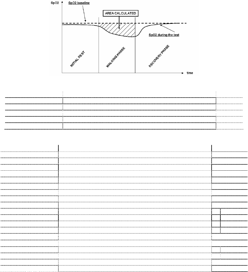
AUC/Distance Area under SpO2 curve base relative to distance covered \
Dyspnea Borg CHG Variation in grade of dyspnea during walking \
Fatigue Borg CHG Variations in level of fatigue during walking \
∆=DELTA
* Here follows a description of the method for calculating the area below the SpO2 baseline curve:
SpirolabIII – User’s Manual Code MIR 980067 REV 0 Page 15 / 47
Parameters required for walk test:
SYMBOL DESCRIPTION Units
Dyspnea Borg Baseline
Grade of dyspnea before walking \
Dyspnea Borg End Grade of dyspnea after walking \
Fatigue Borg Baseline Level of fatigue before walking \
Fatigue Borg End Level of fatigue after walking \
Walked Distance covered during walking m
Parameters measured with SpO2 Analysis:
SYMBOL DESCRIPTION Units
SpO2 Baseline SpO2 Average in first three minutes %
SpO2 Min SpO2 Minimum during analysis period %
SpO2 Max SpO2 Maximum during analysis period %
SpO2 Mean SpO2 Average during analysis period %
BPM Baseline Average pulse frequency in the first 3 minutes BPM
BPM Min Minimum pulse frequency during the analysis period BPM
BPM Max Maximum pulse frequency during the analysis period BPM
BPM Mean Average pulse frequency during the analysis period BPM
Recording time Total time measure of SpO2 hh:mm:ss
T < 90% Time passed with SpO2 < 90 % %
hh:mm:ss
T < 89% Time passed with SpO2 < 89 % %
hh:mm:ss
T < 88% Time passed with SpO2 < 88 % %
hh:mm:ss
T < 87% Time passed with SpO2 < 87 % %
hh:mm:ss
N° Events SpO2 < 89%
Fall of SpO2 below 89 % for at least 20 seconds \
∆ Index [12s] Index of SpO2 fluctuation calculated in intervals of 12 seconds \
T< 40 BPM Time passed with pulse frequency < 40 BPM %
hh:mm:ss
T> 120 BPM Time passed with pulse frequency > 120 BPM %
hh:mm:ss
N° Events < 40 BPM Bradycardia events during the entire analysis period \
N° Events > 120 BPM Tachycardia events during the entire analysis period \
∆=DELTA
Acoustic signals for oximetry:
• Beep with frequency of the cardiac pulse
• Continuous beep in the case of either %SpO2 or cardiac pulse going outside of the programmed alarm levels
• Continuous beep during oximetry measurement in the case of low battery level
The specifications for both the oximetry and for the cardiac pulse are the same, regardless of which of the above
mentioned oximetry sensors is used.
2 PRODUCT DESCRIPTION
SpirolabIII is a spirometer with an optional pulse oximetry module that facilitates the total valuation of lung function. It is
a powerful and compact measurement device intended for use by a physician (respiratory specialist), and which is
capable of calculating more than 30 spirometric parameters.
SpirolabIII is able to make FVC, VC, IVC, MVV and breathing profile tests, as well as the saturation of oxygen in the
blood and the heart beat.
It can operate in stand alone mode, and it can be connected to a PC or to a printer using any one of several available
methods: RS232, USB, Bluetooth.
It calculates an index of test acceptability (test quality control) and a measure of reproducibility; It also gives functional
interpretation with 11 possible levels following the latest ATS (American Thoracic Society) classification; it has an
internal memory sufficient for over 6000 spirometry tests or for 1000 hours (or 40 days) of oximetry monitoring.
The main spirometric parameters are measured and displayed and all data with Flow/Volume and Volume/time curves
can be printed out in seconds by the built-in thermal printer. The Flow/Volume curve is shown in real time on the display.
SpirolabIII – User’s Manual Code MIR 980067 REV 0 Page 16 / 47
Each test can be repeated as required. The best parameters are always available for quick viewing or printing. The
normal (predicted) values can be selected from five different authors. In general, within the European Union the ERS
(European Respiratory Society) predicted values are used.
The device also calculates the response to drug administration, i.e., the percentage change between spirometry results
obtained before and after the subject takes a drug) and the results of a bronchial challenge test or a bronchodilation
test. A comparison of data is made between POST (after-drug) and PRE (before drug administration).
The flow and volume measurement sensor is a digital turbine, based on the infrared interruption principal. This principal
ensures the accuracy and the reproducibility of the measurements without requiring a periodic calibration.
The main features of this kind of sensor are listed below:
• Accurate measurement even at very low flow rates (end of expiration)
• Not influenced by gas humidity nor density
• Shockproof and unbreakable
• Inexpensive to replace
The turbine flow measurement sensor is available both in reusable and in single-patient disposable versions.
REUSABLE TURBINE
SINGLE-PATIENT DISPOSABLE
The following precautions must be observed to ensure that the characteristics of the turbine remain unaltered over time:
• For the disposable turbine: must always be substituted between patients.
• For the reusable turbine: always clean the turbine between patients, to ensure the maximum level of hygiene and
safety for the patient.
For a correct interpretation of a spirometry test, the measured values must be compared either with the so-called
normal or predicted values which are calculated from the anthropometric details of the patient or, alternatively, with the
personal best values from the clinical history of the subject.
The personal best values can vary considerably from the predicted values, which are taken from “healthy” subjects.
SpirolabIII is supplied with an RS-232 optoisolated serial communication port, which guarantees excellent electrical
protection (> 4 KV) both for the health care worker and for the subject, in compliance with the most strict European
safety standards (EN 60601-1).
The Bluetooth connection system can be used to connect the device directly to a printer (the Bluetooth system must be
installed and enabled on the printer as well).
SpirolabIII can also be connected to a PC (or to another computerised system) to configure the system. All spirometric
test results plus the related subject details stored inside the device can be transferred from the device to the PC and
then viewed within the winspiroPRO PC software (Flow/volume curves, spirometry parameters, plus optional oximetry
parameters).
The connection to the PC can be made in the following ways:
• through the RS232 port or
• through the USB port
The internal software (or firmware) of the device can be upgraded quickly and simply from a PC.
For upgrading the system consult the manufacturer or an authorized representative.
SpirolabIII gives an automatic interpretation of each spirometry test carried out, and assigns a “traffic light” feedback
(green, yellow or red) to each test or series of tests. The set up of the traffic light settings is made by the doctor
responsible for the system configuration.
Oximetry function
The oximetry sensor has two light emitting diodes (LEDs), one emits in the visible spectrum and one infrared. Both lights
then pass through the finger and are “read” by the receiver. As these lights pass through the finger, a proportion of the
light is absorbed by the blood and by the soft tissue, in function of the concentration of heamoglobin. The quantity of
light absorbed, at each frequency, depends on the degree of oxygenation of the haemoglobin inside the soft tissue.
This measurement principal ensures accuracy and reproducibility, without requiring regular calibration.
The oximetry sensor can be disinfected with isopropilic alcohol.
The operating battery is a 3.6V lithium battery.
SpirolabIII – User’s Manual Code MIR 980067 REV 0 Page 17 / 47
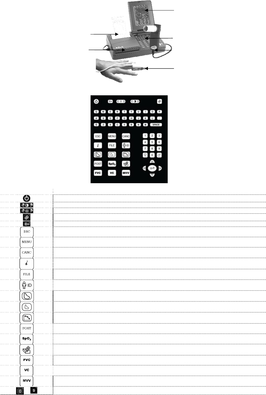
2.1 ILLUSTRATION OF SPIROLABIII
Thermal paper container
Flow sensor compartment
Display
Keyboard
Miniflowmeter sensor
Oximeter sensor
2.2 KEYBOARD
SYMBOL DESCRIPTION
On/Off
Adjust contrast, press several times as required
Adjust brightness, press several times as required
Advance the printer paper
Self-check key
Cancel the current operation
Select configuration menu
Correction key/cancel last data inserted
Information about options
View data in memory
Enter/modify patient data
View best test
View last test
View bronchodilation tests
Make POST test
Make oximetry test
Print
Make FVC test
Make VC test
Make MVV test
... Number keys
SpirolabIII – User’s Manual Code MIR 980067 REV 0 Page 18 / 47
Specifies female sex
Specifies male sex
Confirm last operation. This key is the ENTER key
Move cursor
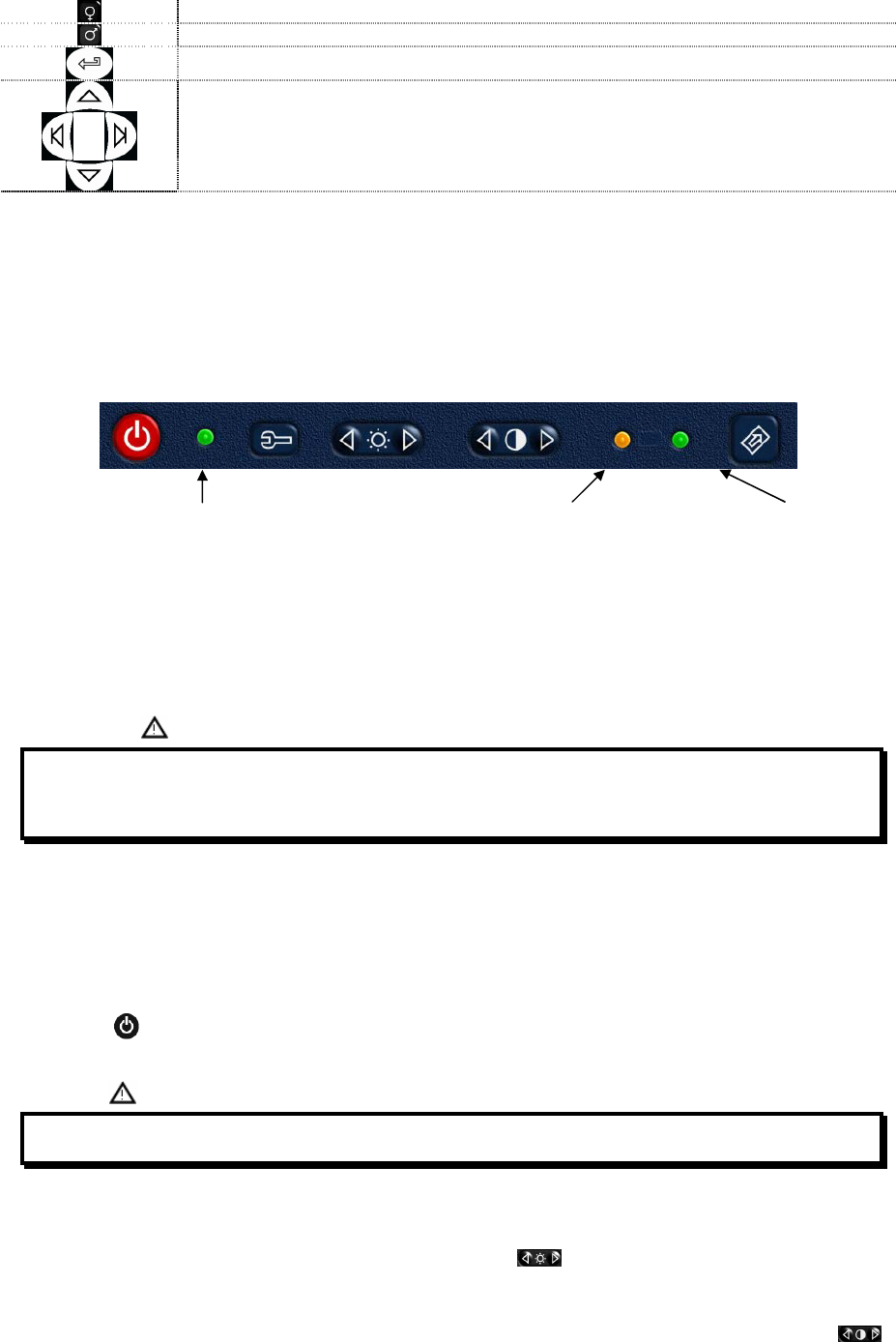
2.3 CHARGING THE BATTERY
Make sure that the electrical information on the label of the charging unit corresponds to that of the power source.
Plug the power supply into an electrical outlet.
Plug the power supply jack into the socket on the back of the device.
Do not use the power supply if it is wet or damp.
Green LED
POWER ON Orange LED
Battery charging Green LED
Battery charged
The charging process has several phrases which are indicated by two LEDs, green and orange (as shown above).
• Immediately after connecting the power supply, the orange LED starts to flash.
• After a few seconds the orange LED stops flashing and remains lit.
• For about 10 minutes the charging is partial while device automatically checks the battery condition.
• After about 10 minutes the charging starts and proceeds to a full charge.
• When charging is completed, the orange LED turns off and the green LED lights up.
' '
' * ' 1 7 9- :
%
2.4 SWITCHING ON THE SPIROMETER
First check that all the accessory items are in good condition.
Before using the device proceed with the cleaning and sterilizing operations, as described in the MAINTENANCE AND
CLEANING section.
Lift the LCD display, release the catch.
Press the red on/off key on the upper left corner of the keyboard. When the device is on, the green led on the right
hand side of the on/off key will light up.
< =( ! 3 ? ' ' '
2.5 SETTINGS
Backlight settings
To adjust the brightness of the display back light use the double key . Press several times as required, on the left
to diminish the brightness or on the right to increase it.
2.5.1 Contrast settings
To adjust the display contrast , to account for the angle of vision and the surrounding lighting, use the double key .
Press several times as required, on the left to diminish the contrast or on the right to increase it.
SpirolabIII – User’s Manual Code MIR 980067 REV 0 Page 19 / 47
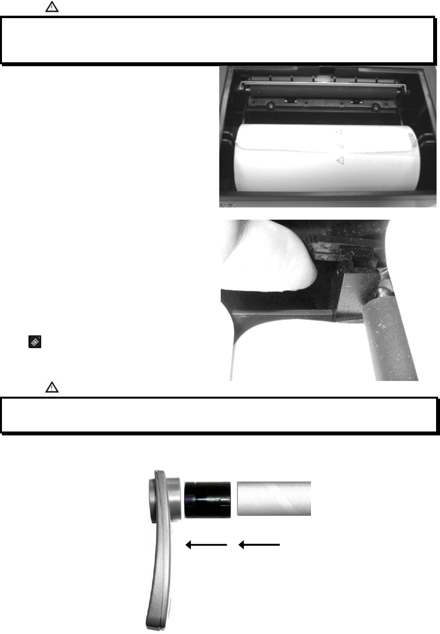
2.5.2 Loading the thermal paper
Open the lid of the thermal paper compartment and remove it from the device; remove the paper roll holder.
Insert the new roll of paper onto the paper roll holder.
'
6
Guide to the correct positioning of the paper roll holder
Push the paper into the slot located under the traction
reel (black rubber reel).
A sensor (as indicated in the image) detects the paper
and automatically advances it.
This image shows the position of the paper in relation to
the traction reel. The paper must advance through the slot
in the compartment when it is closed; close the lid of the
compartment.
If necessary make the paper advance manually by
pressing
& ' ..2 ' *
' E 7 &
2.5.3 Connecting the flow sensor
The flow sensor is made up of the elements shown in the following illustration.
Miniflowmeter Turbine Mouthpiece
SpirolabIII – User’s Manual Code MIR 980067 REV 0 Page 20 / 47
Before carrying out a spirometry test, verify that there are no foreign bodies present inside the flow sensor.
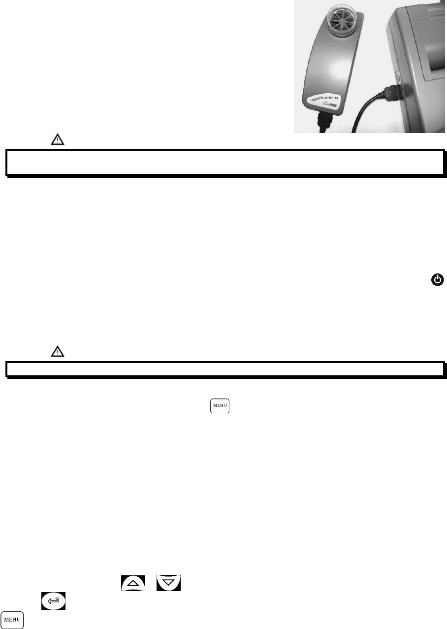
Connect the connection cable to the Miniflowmeter until hearing the ‘click’
which indicates that it has been correctly inserted. Connect the other end to
the SpirolabIII as shown in the image; again the ‘click’ will indicate the
correct insertion.
Make sure that a new disposable mouthpiece has been correctly inserted in
the turbine (mouthpiece holder).
8'
Remove the used mouthpiece and dispose of it after finishing the spirometry testing.
When the flow sensor head is not in use, we recommend that it is kept in its compartment.
Press lightly on the connector to detach the flow sensor turbine from the socket on the left hand side of the device and
proceed with the cleaning operations as outlined in the MAINTENANCE CLEANING section of the manual.
2.5.4 Switching off the spirometer
The device has an auto power-off system for reducing battery consumption. This feature can be set up from the menu by
selecting one of the following 3 options: 6, 60 or 240 minutes; the device will automatically switch off upon reaching the
pre-set time, when no activity has been made for that time.
If instead the device remains switched on when all operations are complete, switch it off manually by pressing .
When the device is switched off, the green (LED) indicator on the right hand side of the on/off key should also be off.
When the battery does not need charging then be sure to detach the power supply from the power supply socket on the
back of the device and remove the charger from the mains supply.
2.5.5 Initial settings
' '
SpirolabIII allows for the personalised setting of certain parameters through the Configuration Menu.
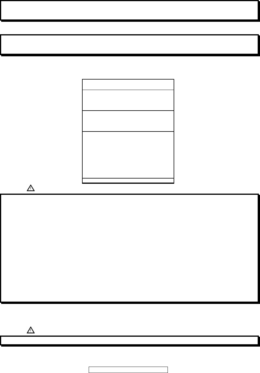
To access the menu, with the device switched on, press which contains the following list:
• Delete data in memory
• Print last calibration
• Turbine calibration
• Printout header text
• Change Date/Time
• Select language
• Select predicted values
• Setup printout
• Bluetooth setup
• Turbine
• Standard
• Date format
• Units format
• Auto power-off
Select the required option using or , until the symbol on the left of the screen is alongside your selection;
then press to access the option.
Use this key to recall the Configuration Menu, to set-up and/or to change certain main functions of the device.

SpirolabIII – User’s Manual Code MIR 980067 REV 0 Page 21 / 47
CONFIGURATION MENU
Delete data in memory
Print last calibration
Turbine calibration
Printout header text
Change DATE/TIME
Choose operating language
Choose predicted values
Setup parameters/printout
Bluetooth settings
•
••
• TURBINE : disposable
•
••
• STANDARD : ATS/ERS
•
••
• DATE format : dd/mm/yy
•
••
• UNITS format : cm, Kg
•
••
• Auto power-off : 60min
•
••
• TO MODIFY THESE SETTINGS
SELECT AND PRESS ENTER
Delete data in memory
To delete all the data in memory.
The display will show:
Use to quit without deleting the test data.
The password is: 122333
After deleting the data in memory, the display shows:
Test data has been DELETED!
Available memory is: 100%
PRESS ANY KEY TO EXIT
If the password is entered incorrectly, the display shows:
ESC to Quit
Press to repeat the procedure.
Print last calibration
To print the turbine calibration coefficient currently in use plus the date of the last calibration made.
Turbine calibration
SpirolabIII – User’s Manual Code MIR 980067 REV 0 Page 22 / 47
' #
'
'
% ' %
8 1 A
To modify the calibration of the turbine based on the FVC values (for the expiratory phase) and FIVC (for the inspiratory
phase), measured during a test made with a calibration syringe.
SYRINGE VOLUME cL: 300
OLD BTPS %ERR
FVC 0 .00
FIVC 0 .00
ESC to Quit
New ATP
FVC
FIVC
If FVC AND FIVC =0 then
Use factory calibration
%ERR = TOTAL ERROR
BTPS = Measure condition
ATP = Conversion from BTPS
SYRINGE VOLUME cL: 300
OLD BTPS %ERR
FVC 0 .00
FIVC 0 .00
ESC to Quit
New ATP
FVC
FIVC
If FVC AND FIVC =0 then
Use factory calibration
%ERR = TOTAL ERROR
BTPS = Measure condition
ATP = Conversion from BTPS
= = '
? =3 ? =3 ' '
91 /F( :
' G3 0 0 3 0 A! @ 8! ( 3 @ G 3 9; -
3 .- .+ + 1 :) 1 1 &1 , F(
)' %? =3 91 /F( : 2 - H 6
? =3 .7 2 - 1 1 F( ' 2 - H ? =3
)' #.7 2-
8 ' ? =3
8 2 7 F( ' E 7 H ? =3 ..7 2
I.7 2 H
' D
? =3
It is possible to insert the volume in cL of the calibration syringe used. For example, for a 3 litre syringe enter 300 cL.
Insert both the FVC and FIVC values measured in a test with a calibration syringe. The calculated coefficient correction
factors are shown.
< ' 9:
If they are < 20 % then the new correction %s are shown.
If the percentage is greater than 20%, then the display shows:
ATTENTION: ERROR out of range
This means that the system cannot correct for such a large calibration error.
The display shows the previous calibration (Previous) with the FVC and FIVC values and the percentage differences
(diff %).
If no calibration has ever been made then FVC and FIVC are equal to the nominal value of the syringe, thus the
percentage differences are null.

SpirolabIII – User’s Manual Code MIR 980067 REV 0 Page 23 / 47
To cancel the current calibration factor and thus reset the calibration factor to the original value set by the manufacturer,
enter 0 (zero) in the space reserved for the FVC and FIVC values.
1 A % 8; ( 9 :'
1 7 7 98; ( :).7 2- 9? =3 :J1 7 K A98; ( ? =3 :
27 F( 8; ( 9 :'
1 7 7 98; ( :)..7 2 9? =3 :J1 1 .A98; ( ? =3 :
' ' ? =3
GG' )
8'
2 7 F( 8; ( J1 7 K 8; ( J1 1 7
#L
#)
Printout header text
To insert a header that will be printed at the beginning of each
spirometry report (see image).
PRINTER HEADER TEXT
INSERT YOUR PRINTER HEADING,
USING UP TO 40 CHARACTERS
¦
ESC to Quit
PRINTER HEADER TEXT
INSERT YOUR PRINTER HEADING,
USING UP TO 40 CHARACTERS
¦
ESC to Quit
Change DATE/TIME
To change the date and time.
The time is shown in the 24 hour format.
Select language
To change the language used for displaying messages on the screen and the printouts.
Select predicted values
To select one of the standards available for the calculation of the predicted values.
Select printout
To enable or disable the printout of spirometry parameters; in addition this menu allows to set-up, enable or disable the
printout of the F/V and V/t curves.
Bluetooth settings
Select this function and the following menu is shown:
• Search Device
• PRINTER Options
• PHONE Options
• Insert Phone Number
• BT TEST
Search Device
Select the required option with and confirm with ; SpirolabIII begins to search for Bluetooth active devices;
when one or more active devices are found then a list is shown, select a device and push to define the device
(with vertical scroll) as a printer or as a phone (use PRINTER or PHONE); select one of the two options and push
, otherwise push to return to the Bluetooth options.

SpirolabIII – User’s Manual Code MIR 980067 REV 0 Page 24 / 47
PRINTER Options
To control the devices memorized within the “printers list”. Enter the list with and having selected a device it is
possible to set the device as default (so SpirolabIII will automatically connect to this) or to delete the device from the list
(SpirolabIII asks for a confirmation by pressing , otherwise press to return to the Bluetooth options and not
delete the device from the list).
PHONE Options
To control the devices memorized in the “printers list”. Enter the list with and having selected a device it is
possible to set the device as default (and SpirolabIII will automatically connect to this) or to delete the device from the
list (SpirolabIII asks for a confirmation by pressing , otherwise press to return to the Bluetooth options and
not delete the device from the list).
Insert Phone Number
Enter the menu with then it is possible to insert the telephone number that SpirolabIII will use to connect to a
Bluetooth telephone. Insert the required number using the numeric keyboard and then press .
Turbine setup
Select the type of turbine to be used for testing, either single-patient disposable or reusable. To select the correct
option, follow the steps as described previously selecting the required item and press to change the option.
Standard
To select one of the available standards: ATS/ERS or NANO III, press .
DATE format: dd/mm/yy
To select the required format, toggles between dd/mm/yy or mm/dd/yy or yy/mm/dd or vice versa.
Press to toggle.
UNITS format: cm, kg
To change the units format from cm, kg to in, lb (inches and pounds) or vice versa.
Press to toggle.
Auto power-off: 6 min
To change the wait-time for auto power off to 6 min, 60 min or after 240 min.
Press to toggle.
2.5.6 Functioning of the spirometer
SpirolabIII performs the following measurements:
Forced Vital Capacity
Slow Vital Capacity
Maximum Voluntary Ventilation
SpO2/BPM
The valuation and interpretation of test results are given by comparing the measured parameters with specific ‘normal’
spirometry values (known as predicted values) which are calculated from subject data: age, height, weight, sex and
ethnic group.
For the calculation of the predicted values, there are several different sets available both for adults and for children.
For adults ERS (European Respiratory Society)
“ Knudson
“ Morris/Bass
“ Multicentrico Barcellona
For children Knudson
“ Zapletal

SpirolabIII – User’s Manual Code MIR 980067 REV 0 Page 25 / 47
After each test session the results are compared to the selected predicted values and the percentage ratio between
measured and predicted is shown for each parameter.
Measured
% Predicted = Predicted x 100
The test can be repeated more than once and the best result is memorized in order to be recalled from the SpirolabII’s
memory.
The best test result is determined following the ATS/ERS standards.
In practice, the best test is the one having the highest sum of FVC+FEV1.
All tests are analyzed by applying the quality criteria (quality control), following the ATS standards. In addition, the
reproducibility of the FEV1, FVC and PEF parameters are also calculated.
It is possible to perform POST drug testing, in this case the test results are compared to a test made prior to the
administration of drugs (PRE-test).
SpirolabIII displays and prints the Flow/Volume and the Volume/time curves superimposed, with PRE and POST
parameter comparison and percentage of change:
Value POST
% PRE = Value PRE x 100
After switching on the device, the main screen will show a summary of the current patient data.
Spirolab III v. x.y
DATE 23/05/06 TIME 12:44:00
PRE FILE N° 1 MEM. 100%
LAST NAME
FIRST NAME
#ID
BIRTH DATE 0/ 0/ 0
HEIGHT cm0 AGE 0
WEIGHT kg 0 SEX
ETHNIC G.
SPIROMETRY INTERPRETATION
CHOOSE ANY FUNCTION
Spirolab III v. x.y
DATE 23/05/06 TIME 12:44:00
PRE FILE N° 1 MEM. 100%
LAST NAME
FIRST NAME
#ID
BIRTH DATE 0/ 0/ 0
HEIGHT cm0 AGE 0
WEIGHT kg 0 SEX
ETHNIC G.
SPIROMETRY INTERPRETATION
CHOOSE ANY FUNCTION
Some values shown are as follows:
v. x.y
Indicates the version of the software (firmware) inside the spirometer. In case of technical problems always note this
version number.
DATE AND TIME
The current date and time, which can be modified from the Configuration Menu.
PRE
The first test for each new subject is a PRE type, ie without drug administration.
For the POST test i.e. after the administration of drugs, see Paragraph 2.6.2 POST in this Manual.
FILE
SpirolabIII assigns a progressive number to each new PRE, POST or SpO2/BPM oximetry test.
#ID
Indicates the subject number or identification code which is inserted by the user.
If the ID code inserted already exists in memory then the following message appears:
WARNING! #ID ALREADY ASSIGNED
CONFIRM ID CODE OR MODIFY
The user may either exit, enter a new ID code, or continue by using the patient file in memory.
SPIROMETRY INTERPRETATION
Indicates the test interpretation.
SpirolabIII – User’s Manual Code MIR 980067 REV 0 Page 26 / 47
2.5.7 New subject data entry
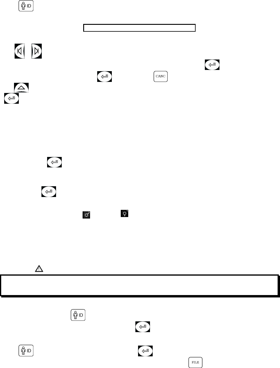
Press .
The lower part of the screen will show the following message:
CHANGE
NEW
SUBJECT NAME AND SURNAME
Use or to modify data of a patient already inserted, or to enter the details of a new patient.
Enter the required information using the cursor positioned on the subject’s surname. Use to go to the next entry.
All data entered must be confirmed with or cancelled with . To modify a number after it has been entered
use ; to return the cursor to the area required, to enter the correct numerical value and go to the next entry press
.
#ID
Insert the patient ID code: this code is alphanumerical and can be a maximum combination of 16 characters; this code
enables the quick recall of any patient data when required.
Recall a subject from memory and press the #ID key to create a new test session with the anthropometric details of the
same subject. This avoids having to reinsert all of the data of that patient.
HEIGHT
Enter the subject’s height (in cm or in inches, according to the current configuration), using the numeric keyboard. Go
to next entry using .
WEIGHT
Enter the subject’s weight (in Kg or Pounds, according to the current configuration), using the numeric keyboard. Go to
next entry using .
SEX
Select gender using the keyboard, for male and for female.
ETHNIC GROUP
A list of possible ethnic groups appear, enter the number corresponding to the required ethnical group.
By matching a subject to an ethnic group, the predicted values for that subject are then modified by a percentage
determined by the ERS and published in: THE EUROPEAN RESPIRATORY JOURNAL Volume 6, Supplement 16
March 1993, Standardized Lung Function Testing § 5.3.
? 7 9*:'
.7 ' E 7 H 2 7 7 H
2.5.8 Modify subject data
To modify subject data press and repeat the data entry procedure.
AIl data not to be modified must be confirmed by pressing .
2.5.9 Automatic insertion of a subject FILE
Press . Enter the existing subject ID code, and press
In case the ID code of a subject’s FILE cannot be remembered then search using .
2.6 SPIROMETRY: FVC, VC/IVC, MVV
All subject data must be entered before carrying out a spirometry test.
The test can be made from the main screen or from any display that shows a previous test result (last test, best test or
test in memory).

SpirolabIII – User’s Manual Code MIR 980067 REV 0 Page 27 / 47
Select the spirometry test:
To make the FVC test
To make the VC/IVC and ventilatory profile tests
To make the MVV test.
When a test is being performed the display will show the real time Flow/Volume curve or the Volume/time curve.
The test must begin within 30 seconds of pressing the start key, otherwise the test is interrupted and the device returns
to the main screen.
2.6.1 Spirometry testing
Insert a new mouthpiece into the MiniFlowMeter mouthpiece holder.
Fit the nose clip onto the nose of the subject, to ensure that air cannot escape through the nostrils.
The subject must insert the mouthpiece well into the mouth, it should be inserted at least 2 cm beyond the front teeth
and held between the teeth, closing the lips to ensure that air cannot escape from the sides of the mouth.
Breathe as directed according to the test to be undertaken, details follow.
Make the test in either a standing or a sitting position. During total expiration (slowly or forced) lean forward to help the
expiratory action with a compression of the abdomen.
FVC
If required (this part is optional), before the test make several breaths at rest. When ready, inspire slowly as much air as
possible (opening the arms helps) and then expire all of the air as fast as possible. Then, without removing the
mouthpiece from the mouth, finish the test by inspiring again as fast and as completely as possible.
This final inspiration is not necessary in the case that the inspiratory parameters (FIVC, FIV1, FIV1%, PIF) are not
required.
The cycle can be repeated several times, without removing the mouthpiece, in which case SpirolabIII will automatically
select and show the best test and measured parameters.
To end test press or just wait for 3 seconds after the last volume cycle, the test terminates automatically.
8; ( % ' 8; ( 8; .
=8'
VC/IVC and Ventilatory Profile tests
It is possible (optional) to begin the test by making several complete breaths at rest. After three or four similar breaths, a
message (VC/IVC) on the display will indicate that the ventilatory profile has been measured and you can now proceed
to carry out the VC or IVC test.
VC test: When the message VC/IVC appears, inspire slowly as much air as possible into the lungs and then expire
slowly as much air as possible.
IVC test: When the message VC/IVC appears, expire slowly as much air as possibile and then inspire slowly as much
air as possible.
To end the test press or wait 3 seconds after the last volume cycle.
If you make the test without the ventilatory profile (respiratory function at rest) then the measured parameter will be only
VC or IVC. Instead, by carrying out several complete breaths at rest, then in addition all measured parameters of the
ventilatory profile will be given.
MVV
Start the test by carrying out a series of forced inspirations and expirations with the maximum possible amplitude. The
suggested frequency is 30 breaths/min. The test will terminate automatically after 12 seconds.
To end test press or wait 3 seconds after the last volume cycle.
At the end of any test, the related curves and the main measured parameters are shown.
After viewing the curves, press to view the remaining test parameters, plus the predicted values and the
percentage ratio between the measured value and the predicted value.
2.6.2 Spirometry post - drug
1st case: current patient data
To perform a POST test on the current subject after completing e PRE test, follow these instructions:
Press to activate the POST phase.
Then quickly carry out the POST test.
SpirolabIII – User’s Manual Code MIR 980067 REV 0 Page 28 / 47
2nd case: subject file
To perform a POST test on a patient already in memory, firstly “recall from memory” the relavant PRE test spirometry
parameters from the same subject file.
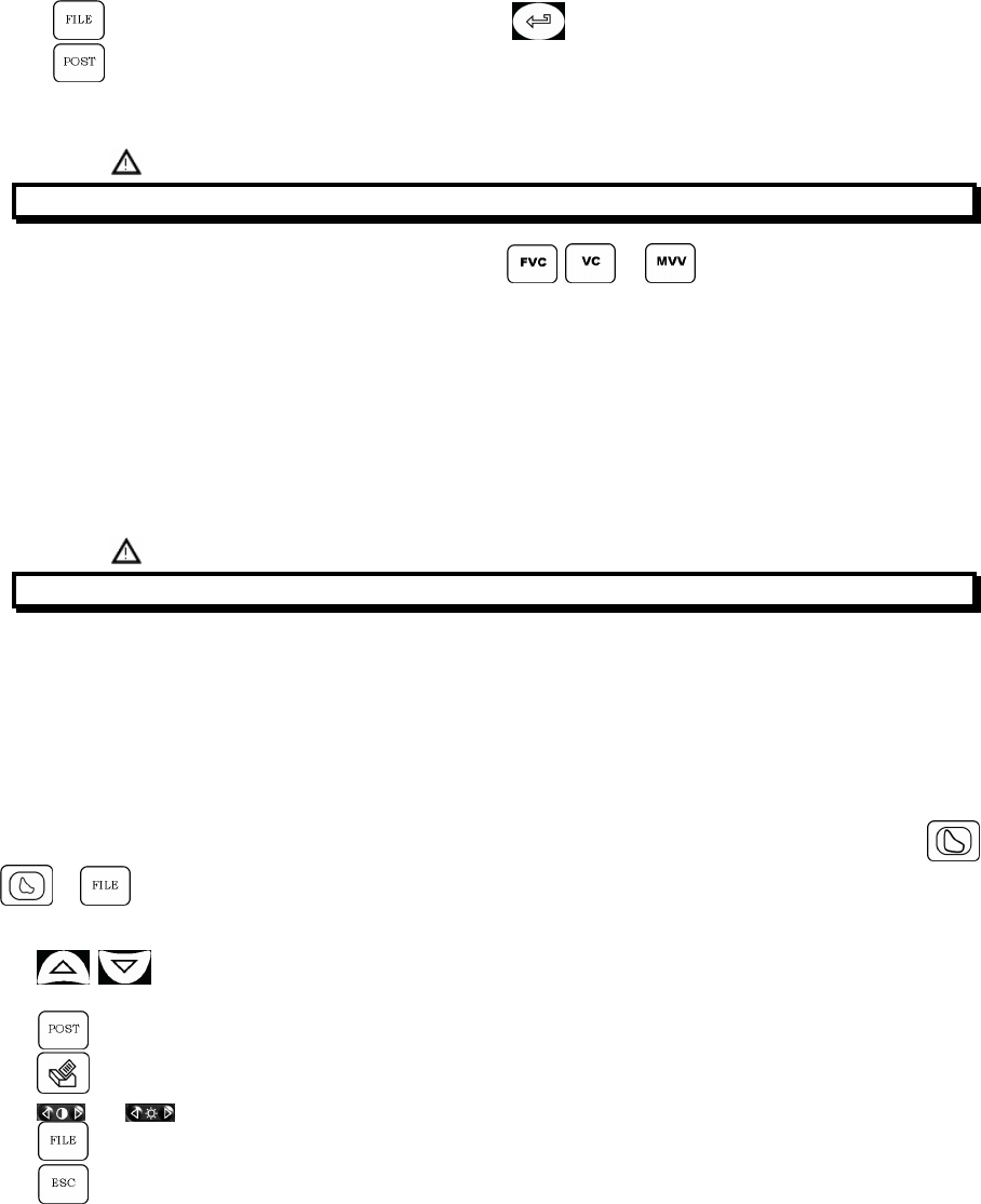
Press ; select FILE NO. from the PRE test. Confirm with .
Press to activate the POST phase.
When the POST phase is activated, the patient data are shown and “POST” appears on the upper left part of the
screen.
=3 8; ( ; ( ; ;
In the POST phase, having selected one of these three tests or , the administered drug dose must
be entered.
Whenever the test is repeated using the same dose, the best test related to the dose used is saved.
When the dose is changed, then a new record is made with a progressive FILE number. For example, if three tests are
made on a subject at different doses, then three different records (POST tests) are saved for that subject.
Afterwards the separate best POST tests can be viewed.
The subject code in the POST test is the same as for the related PRE test.
In the POST phase, the measured result is compared to the values of the related PRE test.
The Flow/Volume curves of the PRE test and related POST test are shown superimposed.
After the two curves, the measured parameters (POST), the related PRE values and the percentage variations between
POST and PRE are also shown.
=3 # '
Physiological test (placebo)
It is common practise prior to a POST test to carry out a test using physiological solution in place of a drug, to examine
the subject’s response to such a stimulus.
If the subject is healthy then the reaction to a placebo is almost zero, but in the case of hypersensitivity even this
stimulus can have some effect.
In the physiological test the amount of the dose to enter is zero and it is still possible to compare the POST results with
those of the PRE test.
The POST phase will show a coloured string highlighting the words POST FILE No. and DOSE.
The POST test can be activated both from the subject file on the main screen and also from the test results (
or ). This makes passing to the POST test phase more simple.
When viewing a subject file, only the following keys can be used:
• keys;
• ID# key (to make a new spirometry test with the current subject’s data file);
• key (to make a POST test);
• (to print selected test);
• and display keys;
• key to go back to the Data Management Menu;
• (exit key);
• No. 1, 2, 3 keys (in the event that one or more tests have been carried out).
2.7 TEST QUALITY CONTROL - SPIROMETRY
Through a mathematical analysis (quality control) which is applied to certain calculated indices and parameters, the
SpirolabIII produces a series of comments, helpful for understanding the reliability of the test made.
ERROR IN Vext and PEFT
If the extrapolated volume Vext is greater than 500 mL or more than 5% of the FVC, or if the PEFT (time to peak flow) is
greater than 200 ms, this message is shown:

SpirolabIII – User’s Manual Code MIR 980067 REV 0 Page 29 / 47
!"#$
FLOW DROP 50%
If the flow rate falls (>50%) and then rises again during the 1st second of a forced expiry, this message is shown:
%& '()*&)
FET ERROR
If the FET is less than the minimum (3 seconds), this message is shown:
+&&,&($$&'&
FLOW ERROR
If the last point of the F/V curve is greater than 200 mL/s, this indicates that the expiration was not complete and thus
this message is shown:
"#(""&&"()
2.8 REPRODUCIBILITY OF THE FVC TEST
Following the international ATS and ERS standards, it is recommended to repeat each FVC test at least 3 times to
ensure the reliability of the spirometry test results. The device helps the user through the reproducibility control check.
Between tests, the reproducibility of the following parameters is calculated:
FVC reproducible if FVC < 5 % or < 200 mL
FEV1 reproducible if FEV1 < 5 % or < 100 mL
PEF reproducible if PEF < 10 %
(delta) indicates the difference between two measured values.
At the end of an FVC test, the reproducibility of a single parameter is indicated alongside the numerical value by a +
sign (reproducible) or a - sign (not reproducible).
An FVC test is defined as reproducible when you have the reproducibility (+) for at least the FVC and FEV1 parameters.
2.9 METHOD OF MEASUREMENT AND INTERPRETATION
The device uses the infrared interruption principle of measurement, with two sets of optoelectronic transmitters and
receivers. A pair of deflectors positioned at the entry and at the exit of the turbine tube generates a vortex in the
passing air, around the axis of the sensor. A rotor with a speed of rotation directly proportional to the air flow then
interrupts the infrared beams and generates a digital signal. The measurement of the air volume that passes through
the tube is proportional to the interruption of the infrared rays.
This measurement principle guarantees stability, reproducibility and reliability over a long period of time, and the
measurement is not affected by gas density, humidity or pressure.
The cleaning of the turbine flow sensor is very simple, and is essential for the protection of the subject from possible
infections. For cleaning and sterilizing operations see Chapter 4 of this Manual.
No calibration of the turbine is required, but it is good practice to make a calibration check by following the simple
instructions contained in the relevant paragraph in the maintenance section of this manual.
Method of test interpretation
Following each FVC test, the device carries out a quality control check to verify the acceptability of the test made and, if
possible, compares the main measured parameters FEV1, FEV1% and FVC with the respective predicted values. It also
calculates a series of indices, based on the following criteria:
measured values
index %=
predicted values x 100
The interpretation of these indices %, according to the ATS standards, generates a series of messages which
correspond to possible levels of obstruction or restriction plus one level of normal spirometry, as shown in the following
table:
Normal spirometry
Possible very mild restriction/obstruction
Possible mild restriction/obstruction
Possible moderately severe restriction/obstruction
Possible severe restriction/obstruction
Possible very severe restriction/obstruction
Light green
Dark green
Light yellow
Dark yellow
Light red
Dark red
SpirolabIII – User’s Manual Code MIR 980067 REV 0 Page 30 / 47
If it is not possible to make the calculations for lack of data, the interpretation is not valid and this message appears:
• Not Valid
For more information on the methods of test interpretation see the attached flow chart.
>' >
2.10 OXIMETRY TESTING
SpirolabIII can carry out different types of oximetry tests, which are described in the following paragraphs.
SpirolabIII ' ) )
'
) 3 2 ' '
SpirolabIII' M"' '
' .
' SpirolabIII
= .2 , D
0 ) SpirolabIII' '
' '
For the non-invasive measurement of the SpO2 oxygen saturation and blood pulse rate utilize the re-usable finger
sensor. This sensor is recommended for patients weighing > 20 Kg with limited activity.
SpirolabIIImemorises the two oximetry values every 2 seconds.
Carry out an oximetry test as follows:
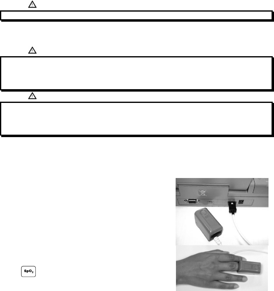
• Connect the sensor to the instrument: insert the connector with the
arrow (printed on the connector) face-up, as shown:
• Choose a high perfusion site, which is easily adaptable to the
sensor.
• Insert finger into the sensor until the finger touches the end of the
probe. Ensure that the bottom part of the finger completely covers
the detector. If the finger is not able to be correctly positioned, use
another finger.
• Position the sensor so that the cable is underneath the palm of the
hand. This enables the light source to remain on the fingernail and
the detector on the bottom part of the finger. From the main screen
press to access the test menu.
• Select required test using the vertical scroll arrow.
If this message appears: OXIMETRY NOT DETECTED
then your instrument does not include an oximeter.
If this message appears:
OXIMETRY DISABLED
the function has not been enabled. In this case contact a service centre or the manufacturer.
The oximetry tests that can be performed by SpirolabIII are:
• Walk test - 6MWT
• SLEEP oximetry
• Oximetry (SpO2/BPM)

SpirolabIII – User’s Manual Code MIR 980067 REV 0 Page 31 / 47
Select required test with , using the vertical scroll arrow, press .
'
' ' '
During the first few seconds of the test the device searches for the best signal, after which the timer re-sets to zero and
SpirolabIIIstarts to memorise the data.
For each type of test, if the sensor has not been correctly inserted, after a few seconds the following message will
appear: WARNING
Sensor unplugged
If the sensor has been inserted but the finger is not inserted correctly, the following message will appear:
WARNING
FINGER not detected correctly
If the sensor correctly receives the signal, after a few seconds the device starts to ‘beep’ and the values will be
displayed on the screen.
2.10.1 Walk Test (6MWT)
This test is made up of 3 phases:
• Baseline (initial rest)
• Walking
• Recovery
Baseline
In this phase the display will show the following data:
• Test time duration
• Signal quality indication
• Current phase
• SPO2 % value and the instant cardiac pulse (heart symbol)
The duration of the test is minimum 2 minutes, then this message appears:
Go to walking phase
press to pass to the following phase. If the phase lasts for more than 6 minutes then SpirolabIIIwill emit a ‘beep’
as a reminder to pass to the walking phase.
The number of bars (“I” symbol) shown on the right upper of the screen is proportional to the quality of the oximetry
signal: the higher the quality of the signal the more bars will be shown (maximum 7). Place finger into the sensor in
order to obtain the highest signal quality.
Walking Phase
At the beginning of this phase the timer is reset to zero, to give an accurate control of the duration of each single phase.
The data on the display is the same as shown before.
The duration of this phase is minimum 2 minutes, this message will appear:
Go to recovery phase
press for a few seconds to pass to the recovery phase. If this phase lasts for more than 6 minutes then
SpirolabIIIwill emit a ‘beep’ after which the device passes to the initial phase and the timer is re-set to zero.
Recovery Phase
The user can decide freely on the duration of this phase, the duration is not suggested (at the beginning of the phase
the timer re-sets to zero).
To end test press .
At the end of the test the data required for the calculation of the parameters must be inserted; more specifically:
• Baseline DYSPNEA
• Final DYSPNEA
• Baseline FATIGUE
• Final FATIGUE
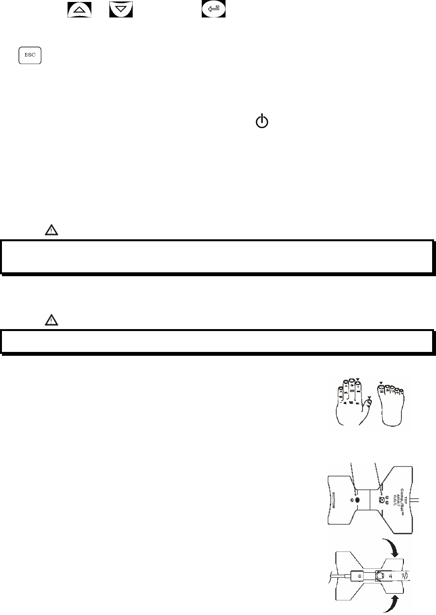
SpirolabIII – User’s Manual Code MIR 980067 REV 0 Page 32 / 47
• DISTANCE (m)
These follow the Borg scale and can have the following values: 0, 0.5, 1, 2, 3, 4, 5, 6, 7, 8, 9, 10, the distance covered is
indicated in m. Use and to enter data; use to pass to next data.
Walk test data results are given in the following screen, and can be printed as described in Paragraphs 2.13 and 3.1.2.
if the test results are printed, the test printout will only show the walk test results; an example of a test printout report is
attached.
Press to end the test at any moment.
2.10.2 Sleep Oximetry
This test records the variations in the patient’s parameters overnight.
After approximately 5 minutes SpirolabIIIwill go to standby i.e., it stops beeping and the display turns off. The led signal
remains on. To control the correct functioning while on standby, press , after 5 minutes SpirolabIIIwill automatically
return to standby. If there is no signal while on standby the device will automatically exit this phase and a warning
message will appear (sensor unplugged or finger not detected correctly).
The data shown are the same as described in the preceding test, except for information on this present phase, which is
not envisaged for this test.
After the required time the test can be interrupted as previously described.
Results can be printed as described in Paragraphs 2.13 and 3.1.2; see example of the test printout report attached to
this Manual.
2.10.3 Oximetry (SPO2 BPM)
' SpirolabIII
§.2 , D
To perform a non-invasive continuous monitoring of arterial oxygen saturation, it is recommended to use the reusable
"wrap" sensor. The use of this sensor is indicated for patients weighing more than 30 Kg and contraindicated for
patients with allergy to adhesive tape.
! AAN=
>
Wrap Sensor – Instructions for Use
• Select the most suitable point to apply the sensor. The index finger is
preferred. Other suggested points may be the thumb, big toe or the smallest
finger.
• It is recommended to use a new piece of adhesive tape for each patient or
according to needs. See instructions for changing the adhesive tape.
• Hold onto the shell at the corner and remove it gently from the sensor.
• Place finger, with nail face-up, on the bottom pad (longer probe) as shown.
Fold the adhesive wing upwards over the sides of the patient’s finger. Do not
pull or stretch the adhesive tape. Do not cover the nail.

SpirolabIII – User’s Manual Code MIR 980067 REV 0 Page 33 / 47
• Fold the pad of the emitter probe over the tip of the patient’s finger. Separate
the window of the emitter so that it is diametrically opposite the window of
the detector.
• Fold the adhesive wings downwards around the finger. Do not pull or stretch
the adhesive tape. Check that the positioning lines of the emitter and of the
detector are aligned.
• Connect the sensor to the instrument: insert the connector with the arrow on
the connector face-up and control the correct functioning according to the
previous instructions.
6
' '
Making a Test
Use to select “Oximetry (SpO2/BPM)” from the oximetry tests list.
The display shows: “Oximetry (SpO2/BPM)”. The test duration is unlimited and the aim is to record variations of the
oximetry values during a period as decided by the doctor.
If the finger is removed from the sensor during the test, the following message will appear:
WARNING
Searching for signal, finger not inserted correctly
To end test, press
To print data see Paragraph 3.1.2; see example of the test printout report attached to this Manual.
2.11 FILE ORGANIZATION
The memory of the spirometer is a ‘string’ of memory areas called records, each of which contain information regarding
a single test session.
More specifically, each record is made up as follows:
• Demographic details of the subject
• Date, time and ambient temperature at the time of the FVC test
• Reproducibility and quality control test information
• Parameters stored with the FVC test:
o FVC, FEV1, PEF, FEF75, FEF2575, FET, *PEF, *FVC, *FEV1, FEV1%, FEV6, FEV6%, FEV1/FEV6%,
FEF25, FEF50, Vext, FIVC, FIV1, FIV1%, PIF, FEV1%/VC%
• Parameters stored with the VC test:
o VC, IVC, * (VC or IVC), ERV, IC, TV, VE, fr, ti, te, TV/ti, te/tt
• Parameters stored with the MVV test:
o MVV
• Points of the expiratory part and (if present) the inspiratory part of the Flow/Volume curves, plus the points of the
Volume/time curve.
• Parameters stored with the SpO2 test (in relation with the test recorded, see also paragraph 1.6.2):
' ' 9
*: O>
Spirometry results can be recalled from the memory.
To access the database, press and select subject FILE No..
The results of the selected test can be printed by pressing
2.12 SEARCH AND READ TESTS IN MEMORY
Positioning
lines
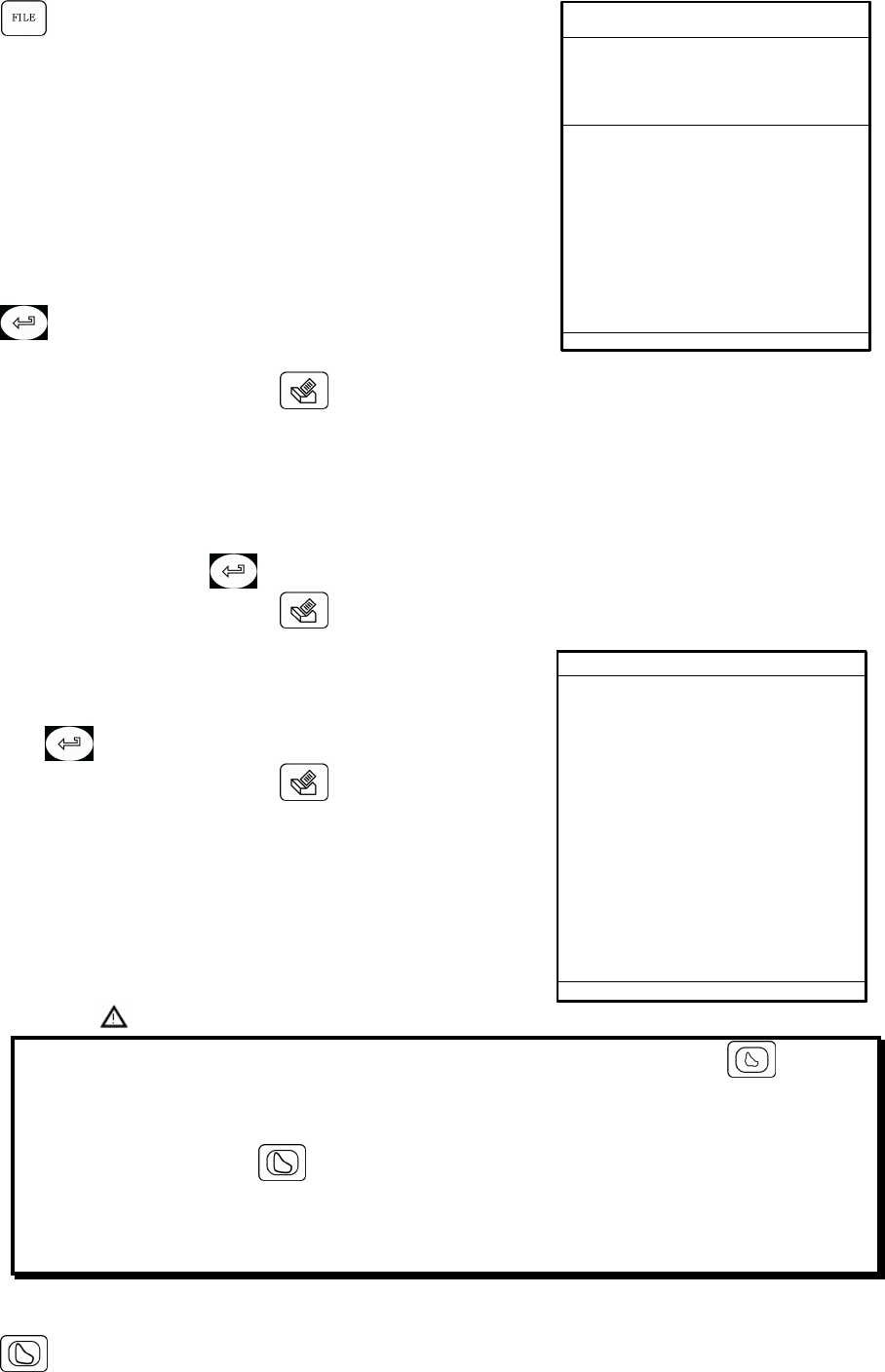
SpirolabIII – User’s Manual Code MIR 980067 REV 0 Page 34 / 47
Press to access menu, from where to view and to print all test
data stored in the memory of the device.
2.12.1 Subject List by name:
This message appears:
ENTER FULL OR PARTIAL SURNAME
TO SEARCH
MATCHING FILES
Use keyboard to enter subject surname or first letters. All corresponding
surnames found in memory will then be listed.
The first column on the right will show the file numbers corresponding to
the tests made, use numeric keyboard to enter required test, press
to view related values.
FIND AND READ TESTS IN MEMORY
Subject List by last name
Subject List by ID code
Memory List
CHOOSE ANY FUNCTION
FIND AND READ TESTS IN MEMORY
Subject List by last name
Subject List by ID code
Memory List
CHOOSE ANY FUNCTION
Indicate FILE No. to view/print corresponding spirometry test results.
Print selected test results by pressing
2.12.2 Subject List by ID#
The following message appears:
ENTER ID# CODE,
OR PARTIAL TO SEARCH
MATCHING FILES
Enter subject ID# and press to view the list containing all patients on file.
Print selected test results by pressing
2.12.3 Subject List
The screen will show the complete test memory list.
Indicate FILE No. to view/print corresponding spirometry test results and
press .
Print selected test results by pressing .
2.13 VIEW AND PRINT RESULTS
MEMORY LIST:
FILE NAME DATE TIME PHASE
Read file N. ¦
MEMORY LIST:
FILE NAME DATE TIME PHASE
Read file N. ¦
0 ' * K 8; ( '
K K '
.K ' .K '
'
0 9' :' ' '
1 1 '
' ' >=3 1
'
From the main screen it is possible to re-examine and to print all the spirometry parameters.
Generates the Flow/Volume curves of the best test.
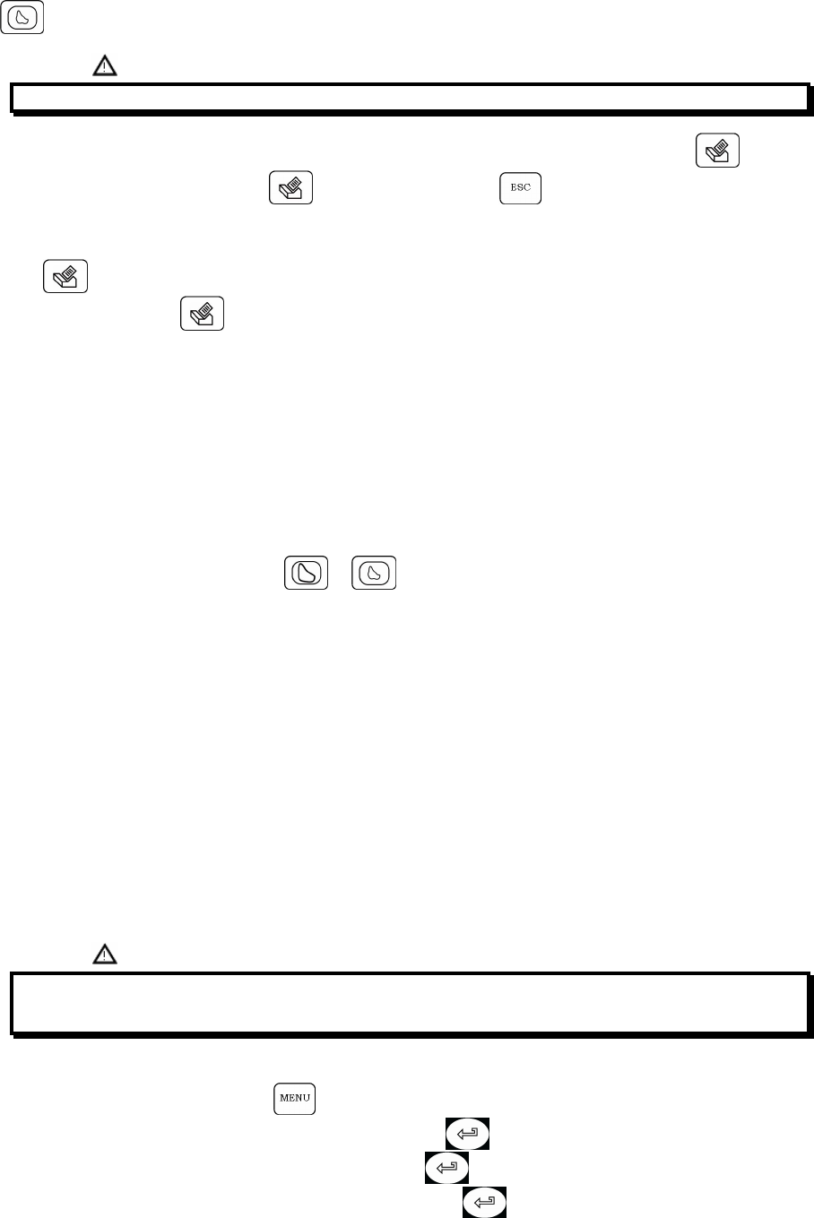
SpirolabIII – User’s Manual Code MIR 980067 REV 0 Page 35 / 47
Generates the Flow/Volume curves of the last test.
'
The data stored in the memory are those of the best tests. The current test can be printed by pressing . To print a
test saved on file after recalling it press . To interrupt printing press .
The printout report includes a header line with the date, time, the BTPS value at the time of the test, patient details, the
FILE No., any pre-set ethnic correction factor and the predicted value set used.
There follow the Flow/Volume and Volume/time curves, which relate to either the last or best test performed.
Press from the main screen to print the best test results.
To print the last test press while viewing the last test.
Lastly, the measured parameters and spirometry test interpretation are shown.
In the case of a PRE test, the following are shown:
Predicted calculated predicted values
PRE measured value before drug administration
%Predicted values percentage value against predicted values
In the case of a POST test then the graph will show the two curves superimposed and in addition to the above-
mentioned parameters, the following values:
POST measured value after drug administration
%CHG % variation (+/-) between POST and PRE.
From the measured parameter’s screen ( or key, or recalled from memory) the subject’s name, date and
time of test is shown on the bottom of the screen.
3 DATA TRANSMISSION
SpirolabIII includes a “Bluetooth” wireless data transmission system. This connection is via radio and allows the
transferring of all the data in memory for two different operations:
• transfer to a cell phone, which then transmits the data to a PC by modem;
• transfer to a Bluetooth-enabled printer, for printing.
The following paragraphs contain in-depth information on these two procedures.
3.1 DATA TRANSMISSION VIA BLUETOOTH TO A CELL PHONE
SpirolabIII can be connected to a cell phone with this system installed. The transmission of data with this technology
allows the transfer of all data in memory of the SpirolabIII.
The sequence of operations to follow is described below.
3.1.1 Preliminary operations
? # '
9" : ( 9
= 2 E E : DD= 2 E E
3.1.2 Setting the Phone Number
• With SpirolabIII switched on, press .
• Use vertical scroll key to select “Bluetooth Set-up” then press .
• Use vertical scroll key to select “Phone Set-up” then press .
• Enter the number with the numerical keyboard, and again press ; the Configuration Menu will appear.

SpirolabIII – User’s Manual Code MIR 980067 REV 0 Page 36 / 47
• Use to return to the main screen.
3.1.3 Data Transmission through Bluetooth
• From the main screen press
• Use vertical scroll keys to select Bluetooth settings and press
• select “intended use” and press
• it is described the transmission way and ,if correct, it is required to confirm it with “OK” to activate the connection to
the device choosen as default in the configuration menu.
• when the request is from mobile phone, type the code shown on the screen (relative to the device’s Serial Number
reported on the back label of SpirolabIII)
• are executed all the next connection steps.
• When the connection is active, data are transmitted from the selected modem
At the end of the transfer data process the following message “Connection Completed” is shown.
The screen will show the following information:
• The device used for the connection;
• The pre-set phone number.
• The preset PIN (corresponding to the serial number of the machine).
To interrupt data transmission during the Bluetooth connection press to end the connection and to return to the
main screen.
Where no device has been setup for data transmission, a message will appear on the display to start searching for
enabled devices. After setting the device the connection will start up automatically.
3.1.4 Data Transmission via Bluetooth for printing
= ? D
! 3 ? %?
The Bluetooth system enables SpirolabIII to transfer test data directly to a printer with Bluetooth. The sequence of
activities to be followed is:
• When the test is finished press twice
• SpirolabIII will carry out the phases of connection.
• At the end of the transmission SpirolabIII will show the message “CONNECTION COMPLETED”, returning
automatically to the main screen
Previous tests stored on file can also be printed. Use the procedure described in Paragraph 2.11 to print required tests.
• When the required test is shown on the display, press twice
To interrupt data transmission during Bluetooth connection press to end the connection and to return to the main
screen.
Where no printer has been set up, a message will appear to search for devices. After the device has been set up it will
automatically be enabled for printing.
When searching for Bluetooth enabled devices, SpirolabIII will check the address of that device and where a previously
registered device has changed name, it will be automatically updated.
3.2 CONNECTION TO A PC
SpirolabIII can be connected to a PC and perform tests online. Two connection types are used: USB port or RS 232
port.
3.2.1 Connection to a PC through a USB port
? SpirolabIII =( ! 3 ? ' = ' '
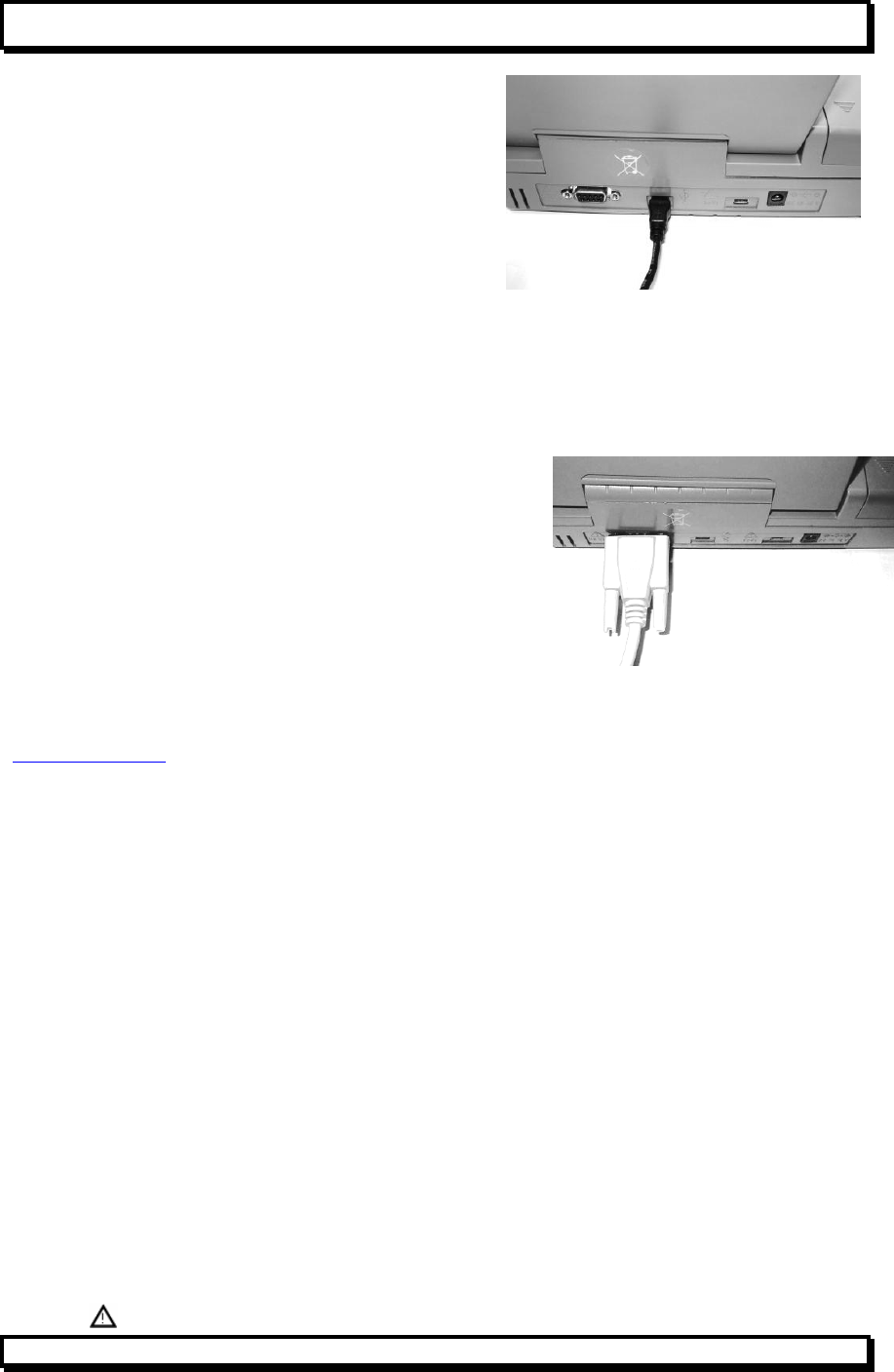
SpirolabIII – User’s Manual Code MIR 980067 REV 0 Page 37 / 47
= ' %' =( 9
( =%B3 C =( %:
To make the connection insert the mini USB connector supplied
with SpirolabIII as shown in the picture and attach the other
connector to the USB port of the PC.
At the first connection, the PC will request the installation of the
driver corresponding to the new device being used; follow the
automatic procedure in the operating system, enter the following
path when the request for the driver appears. Windows 2000 and
higher versions enter the following path:
C\Programmi\MIR\winspiroPro\DriverUSB\win2000-xp
For Windows 98 enter the following path:
C\Programmi\MIR\winspiroPro\DriverUSB\win98
To check the connection between the device and the PC, ensure that the led on the device is on.
3.2.2 Connection to PC through RS 232 port.
SpirolabIII can be connected to a PC through a RS 232 serial port. This
leaves the USB port free. The picture shows the RS 232 connector
attached to SpirolabIII.
For the correct management of the device see the software manual.
3.3 UPGRADE INTERNAL SOFTWARE
SpirolabIII can be upgraded when connected to a PC (via USB or RS232). Upgrades can be downloaded by registering
on www.spirometry.com. For further information on upgrading software see the “winspiroPRO” software manual.
4 MAINTENANCE AND CLEANING
SpirolabIII is an instrument that requires very limited maintenance. The operations to perform periodically are:
• Cleaning and controlling of the reusable turbine.
• Changing the disposable turbine at each test.
• Cleaning of the oximetry sensor (for reusable sensors).
• Changing the adhesive tape of the oximetry wrap sensor.
• Changing the battery.
The maintenance operations described in the User’s Manual must be carried out carefully. Failing to observe the
instructions may cause errors in measurement or in the interpretation of measured values.
Modifications, adjustments, repairs, and reconfiguration must be carried out by the manufacturer or by authorised
persons.
In case problems arise, never attempt to repair the unit.
The setting of the configuration parameters must be carried out by qualified personnel. In any case, the risks from an
incorrect setting do not constitute a danger for the patient.
The device is supplied with an internal lithium battery used to back-up the RAM; the average battery life is approximately
10 years. If this message appears:
Warning! Replace the internal lithium battery
Contact a service centre or the manufacturer for battery replacement.
4.1 CLEANING THE DEVICE
Clean the device with a damp cloth. Make sure to dry it afterwards.
0 ' ' #
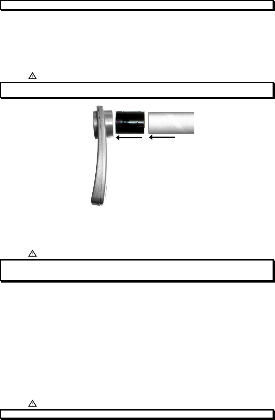
SpirolabIII – User’s Manual Code MIR 980067 REV 0 Page 38 / 47
0
4.2 CLEANING THE REUSABLE TURBINE
The turbine utilized with SpirolabIII is of one of two categories: disposable or reusable. These guarantee precise
measurements and have the advantage of requiring no periodic calibration. In order to maintain these characteristics, a
simple cleaning is required prior to each use (only for the reusable turbine). This operation also ensures perfect
hygiene and thus the highest possible safety conditions for patients.
Cleaning of the disposable turbine is not required as it is supplied already clean in a sealed plastic bag. It must be
disposed of after use.
The maintenance operations to perform are cleaning and controlling of the turbine.
%%
Miniflowmeter Turbine Mouthpiece
To clean the reusable turbine, remove it from its compartment in the MiniFlowmeter by turning it anti-clockwise and
pressing lightly. It can be helpful to push it gently from underneath with one finger.
Immerse the turbine in a cold sterilising liquid and move it within the liquid to remove any impurities which may be
deposited inside. Leave it to soak for at least the time recommended by the producer of the cleaning solution, as shown
in the instructions (in general at least 20 minutes).
> ' #
< '
0 *'
Rinse the turbine by immerging it in clean water (not hot).
Shake off the excess water from the turbine and leave it to dry, standing it vertically on a dry surface.
To ensure that the turbine is functioning correctly before replacing it inside the instrument it is good practice to make a
visual check of the rotation blade. Placing the turbine tube horizontally and moving it gently from left to right and vice
versa, the rotation blade (rotor) must rotate freely. Otherwise, accurate measurement is no longer guaranteed, so the
turbine must be replaced.
Once the turbine has been cleaned, insert the turbine tube in its place following the instructions indicated by the “lock “
symbol printed on the MiniFlowmeter.
To insert the turbine correctly, push it and then turn it clockwise until reaching the stop, which ensures that the tube has
been blocked inside the casing.
Verify the free movement of the turbine:
• Switch on SpirolabIII as if to make a spirometry test (for example FVC).
• Hold the MiniFlowmeter in one hand and move it gently from side to side, so that air passes through the turbine.
• If the rotor within the turbine is turning correctly, then you will hear a beep that indicates that the turbine is moving
within the specific low flow range.
• If moving the turbine from side to side at a constant velocity, regular beeps or no beeps at all are heard, then
proceed with the cleaning of the turbine.

SpirolabIII – User’s Manual Code MIR 980067 REV 0 Page 39 / 47
'
4.2.1 Recommended products for cleaning the reusable turbine
Tests made on the cleaning of the turbine with various products have demonstrated that the best product in commerce
which does not harm the material of the reusable turbine is:
PERA safe
After 100 immersions lasting 10 minutes each at an interval of 15 seconds, PERA safe did not cause any harm to the
turbine. These test results are available from the MIR offices.
8 PERA safe 9 ' : "

SpirolabIII – User’s Manual Code MIR 980067 REV 0 Page 40 / 47
5 PROBLEMS/CAUSES AND SOLUTIONS
The device does not switch on
Press firmly on the on key.
The internal battery may be discharged.
Make sure that the power supply cable of the charging unit is connected to the spirometer and that the plug is inserted
correctly into the mains outlet, then proceed with charging.
The LCD does not display
Using the two keys which regulate the brightness and the contrast of the display.
The battery charging is not working correctly
The device is protected thermically. In case the power supply of the battery reaching a high temperature then a
thermal protection intervenes and prevents the charging.
This thermo protector can intervene if:
• the device has operated beyond the functioning limits indicated in this manual;
• the device is operated near a heat source, or in ambients with a temperature either too high or too low.
Disconnect the power supply and let it cool down before continuing with charging.
The lithium battery for the data memory indicates discharged
If the internal lithium battery is discharged, the spirometry parameters in the memory and other configuration data may
be cancelled automatically.
Contact an authorized service centre to replace it.
The printer does not print
The thermal paper may have run out.
Insert a new roll of thermal paper.
The printer is in thermal protection
The printer is also protected thermically. In case the printer reaches elevated temperatures then a thermal protection
intervenes and blocks the functioning of the printer.
A message on the display appears to signal the protection.
Let the printer cool down before turning on the device again.
The printer makes noises
Make sure there is a sufficient quantity of thermal paper.
Make sure that the thermal paper and the thermal paper holder are positioned correctly.
Make sure that the thermal paper container lid is in the correct position.
The device does not measure
Make sure that the turbine’s cable is connected to the spirometer and that the plug is inserted properly in the
appropriate connector.
Make sure that the turbine is inserted correctly into the MiniFlowmeter.
The device does not measure correctly
Make sure the turbine is inserted correctly in the MiniFlowmeter. Verify the free movement of the turbine as illustrated
in Paragraph 4.2.
*
SpirolabIII – User’s Manual Code MIR 980067 REV 0 Page 41 / 47
5 LIMITED WARRANTY CONDITIONS
This MIR product together with its standard accessories is guaranteed for a period of ONE YEAR from the date of
purchase. In the case of any warranty claims the relevant sales invoice (or another proof of purchase document) must
be submitted to MIR.
The instrument must be checked at the time of purchase, or upon delivery, and any claims must be made within 8 days
in writing to the manufacturer.
This warranty covers the repair or the replacement (at the discretion of the manufacturer) of the product or of the
defective parts without charge for the parts or for the labour.
All batteries and other consumable parts are specifically excluded from the terms of this guarantee.
The instrument must be returned to the authorized service centre for repair within 8 days from when the defect is
detected.
This warranty is not valid, at the discretion of the manufacturer, in the following cases:
• If the fault is due to an improper installation or operation of the machine, or if the installation does not conform to
the current safety norms in the country of installation.
• If the product is utilized differently from the use described in the User’s Manual (improper, incorrect and/or
unreasonable use, etc.).
• If any alteration, adjustment, modification or repair has been carried out by personnel not authorised by MIR or by
the user.
• If the fault is caused by lack of or incorrect routine maintenance of the machine.
• If the machine has been dropped, damaged or subjected to physical or electrical stress.
• If the fault is caused by the mains or by another product to which the instrument has been connected.
• If the serial number of the instrument is missing, tampered with and/or not clearly legible.
This warranty does not cover any liability for damage, caused directly or indirectly, of any kind whatsoever for persons or
things for the period in which the device is not in use.
The repair or replacement described in this warranty is supplied for goods returned at the customers’ expense to our
certified service centres. For details of these centres please contact your local supplier of the spirometer or contact the
manufacturer directly.
The customer is liable for all repairs not included under the terms of this guarantee.
The customer is responsible for all transportation charges.
Any instrument or accessory returned must be accompanied by a clear and detailed explanation of the defect or
problem found. If units are to be returned to the manufacturer then written or verbal permission must be received before
any instruments are returned to MIR.
MIR - Medical International Research reserves the right to modify the instrument if required, and a description of any
modification made will be sent along with the returned goods.

SpirolabIII – User’s Manual Code MIR 980067 REV 0 Page 42 / 47
ANNEXES
DECLARATION OF CONFORMITY
srl
MEDICAL INTERNATIONAL RESEARCH
Via del Maggiolino, 125 00155 - Roma - ITALIA
Declaration of EC Conformity
Quality Management System according to the requirements of Annex II of the Medical Device Directive 93/42/EEC.
Notified body CERMET N° 0476 - Certificate of Conformity N° MED – 9826
MIR srl Medical International Research declares that the Device subject of this declaration together with its standard accessories
conforms to the requirements of the Council Directive 93/42/EEC
Annex I.
Device Description Spirometer
Device name spirolab III
Classification IIa
This device is marked with
Any modifications to the Device which are not authorised by us will invalidate this declaration.
Roma …/ …. / 2006
Signature: Signature:
Simon Fowler Carmine Cerullo
Sales Manager Quality Manager
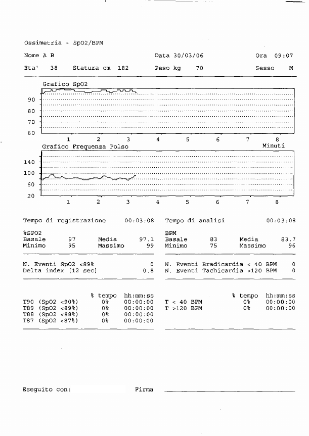
SpirolabIII – User’s Manual Code MIR 980067 REV 0 Page 43 / 47
EXAMPLE OF OXIMETRY TEST REPORT
Spirolab IIISpirolab III

SpirolabIII – User’s Manual Code MIR 980067 REV 0 Page 44 / 47
INFORMATION FOR CORRECT USE IN AN ELECTROMAGNETIC ENVIRONMENT
Guidance and manufacturer’s declaration – electromagnetic emissions
The Spirolab III is intended for use in the electromagnetic environment specified below.
The customer or the user of the Spirolab III should assure that it is used in such an
environment.
Emissions test Compliance Electromagnetic
environment – guidance
RF emissions
CISPR 11 Group 2 The Spirolab III must emit
electromagnetic energy to
perform its indended
function. Nearby electronic
equipment can be affected.
RF emissions
CISPR 11 Class B The Spirolab III is suitable for
use in all establishments,
including domestic
establishments and those
directly
connected to the public low-
voltage power supply
network that supplies
buildings used for domestic
purposes.
Harmonic emissions
IEC 61000-3-2 Class D
Voltage fluctuations/
flicker emissions
IEC 61000-3-3
Complies

SpirolabIII – User’s Manual Code MIR 980067 REV 0 Page 45 / 47
Guidance and manufacturer’s declaration – electromagnetic immunity
The Spirolab III is intended for use in the electromagnetic environment specified below.
The customer or the user of the Spirolab III should assure that it is used in such an
environment.
Immunity test IEC 60601
test level Compliance level Electromagnetic
environment –
guidance
Electrostatic
discharge (ESD)
IEC 61000-4-2
± 6 kV contact
± 8 kV air
± 6 kV contact
± 8 kV air
Floors should be
wood, concrete or
ceramic tile. If floors
are covered with
synthetic material,
the relative humidity
should be at least 30
%.
Electrical fast
transient/burst
IEC 61000-4-4
±1 kV for input/output
lines ±1 kV for input/output
lines Mains power quality
should be that of a
typical commercial or
hospital
environment.
Surge
IEC 61000-4-5
± 1 kV differential
mode
± 2 kV common
mode
±1 kV differential
mode
± 2 kV common
mode
Mains power quality
should be that of a
typical commercial or
hospital environment.
Voltage dips, short
interruptions and
voltage variations
on power supply
input lines
IEC 61000-4-11
<5 % UT
(>95 % dip in UT)
for 0,5 cycle
40 % UT
(60 % dip in UT)
for 5 cycles
70 % UT
(30 % dip in UT)
for 25 cycles
<5 % UT
(>95 % dip in UT)
for 5 sec
<5 % UT
(>95 % dip in UT)
for 0,5 cycle
40 % UT
(60 % dip in UT)
for 5 cycles
70 % UT
(30 % dip in UT)
for 25 cycles
<5 % UT
(>95 % dip in UT)
for 5 sec
Power frequency
(50/60 Hz)
magnetic field
IEC 61000-4-8
3 A/m 3 A/m Power frequency
magnetic fields
should be at levels
characteristic of a
typical location in a
typical commercial or
hospital environment.
NOTE UT is the a.c. mains voltage prior to application of the test level.

SpirolabIII – User’s Manual Code MIR 980067 REV 0 Page 46 / 47
Guidance and manufacturer’s declaration – electromagnetic immunity
The Spirolab III is intended for use in the electromagnetic environment specified below. The customer or
the user of the Spirolab III should assure that it is used in such an environment.
Immunity test
IEC 60601 test level
Compliance level
Electromagnetic environment –
guidance
Conducted RF
IEC 61000-4-6
Radiated RF
IEC 61000-4-3
3 Vrms
150 kHz to 80 MHz
3 V/m
80 MHz to 2,5 GHz
[3 ] V
[3 ] V/m
Portable and mobile RF
communications equipment
should be used no closer to any
part of the Spirolab III, including
cables, than the recommended
separation distance calculated
from
the equation applicable to the
frequency of the transmitter.
Recommended separation
distance
d=[ 3.5 ] P
3
d=[ 3.5 ] P 80 MHz to 800
GHz
3
d=[ 7 ] P 800 MHz to 2,5 GHz
3
where P is the maximum output
power rating of the transmitter in
watts (W) according to the
transmitter manufacturer and d is
the recommended separation
distance in metres (m).
Field strengths from fixed RF
transmitters, as determined by an
electromagnetic site survey,
should be less than the
compliance level in each
frequency range.b
Interference may occur in the
vicinity of equipment marked with
the following symbol:
NOTE 1 At 80 MHz and 800 MHz, the higher frequency range applies.
NOTE 2 These guidelines may not apply in all situations. Electromagnetic propagation is affected by
absorption and reflection from structures, objects and people.
a Field strengths from fixed transmitters, such as base stations for radio (cellular/cordless) telephones and
land mobile radios, amateur radio, AM and FM radio broadcast and TV broadcast cannot be predicted
theoretically with accuracy. To assess the electromagnetic environment due to fixed RF transmitters, an
electromagnetic site survey should be considered. If the measured field strength in the location in which
the Spirolab III is used exceeds the applicable RF compliance level above, the Spirolab III should be
observed to verify normal operation. If abnormal performance is observed, additional measures may be
necessary, such as reorienting or relocating the Spirolab III.
b Over the frequency range 150 kHz to 80 MHz, field strengths should be less than [3] V/m.

SpirolabIII – User’s Manual Code MIR 980067 REV 0 Page 47 / 47
Recommended separation distances between
portable and mobile RF communications equipment and the Spirloab III
The Spirolab III is intended for use in an electromagnetic environment in which radiated RF
disturbances are controlled. The customer or the user of the Spirolab III can help prevent
electromagnetic interference by maintaining a minimum distance between portable and mobile
RF communications equipment (transmitters) and the Spirolab III as recommended below,
according to the maximum output power of the communications equipment.
Separation distance according to frequency of transmitter
m
Rated maximum
output
power of
transmitter
W
150 kHz to 80 MHz
d=[ 3.5 ] P
V1
80 MHz to 800 MHz
d=[ 3.5 ] P
E1
800 MHz to 2,5 GHz
d=[ 7 ] P
E1
0.01 0.12 0.24 0.24
0.1 0.37 0.37 0.74
1 1.17 1.17 2.34
10 5.28 5.28 1.056
100 11.66 11.66 23.32
For transmitters rated at a maximum output power not listed above, the recommended
separation distance d in metres (m) can be estimated using the equation applicable to the
frequency of the transmitter, where P is the maximum output power rating of the transmitter in
watts (W) according to the transmitter manufacturer.
NOTE 1 At 80 MHz and 800 MHz, the separation distance for the higher frequency range
applies.
NOTE 2 These guidelines may not apply in all situations. Electromagnetic propagation is
affected by absorption and reflection from structures, objects and people.