MITSUBISHI ELECTRIC TOKKI SYSTEMS 9JKTD-L1630 SCANNING RECEIVER User Manual
Taiyo Musen Co Ltd SCANNING RECEIVER
UserManual.wiki
>
MITSUBISHI ELECTRIC TOKKI SYSTEMS
>
9JKTD L1630 User Manual
Manual
Navigation menu
Upload a User Manual
Namespaces
Wiki Guide
HTML
PDF
Info
Views
User Manual
Discussion / Help
Navigation

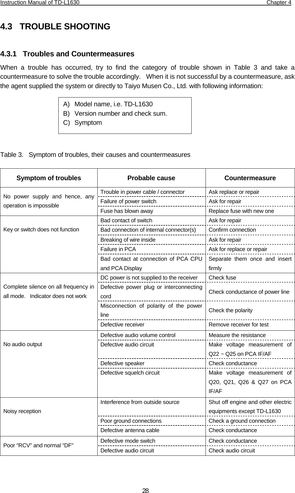
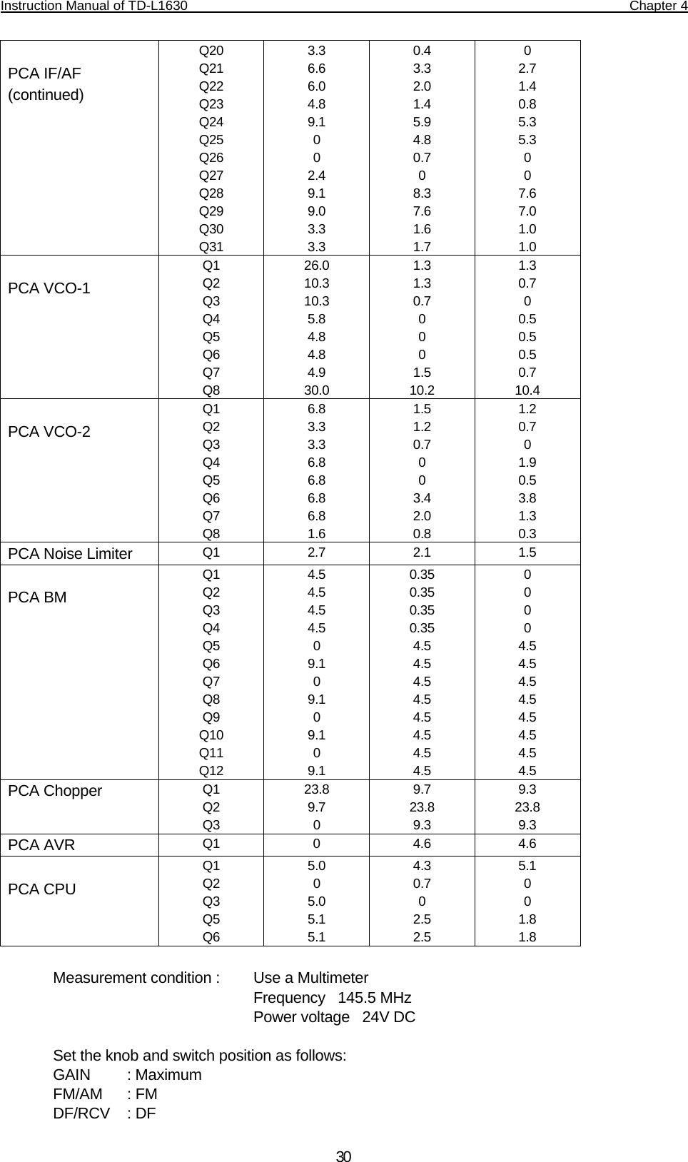
![Instruction Manual of TD-L1630 Chapter 4 29Defective 135.6 Hz output circuit Make voltage measurement J1 and J2 Defective ADDF amplifier circuit Make voltage measurement of Q17 ~ Q31 on PCA IF/AF Defective PCA CPU Replace the PCA CPU Defective PCA DISPLAY Replace the PCA DISPLAY Defective balanced modulator circuit in the Adcock antenna Check diode and transformer Defective antenna cable Check conductance Poor “DF” and normal “RCV” (continued) Defective mode switch Check conductance Poor sensitivity in all mode and all frequency Defective IF amplifier circuit Measure gain value Defective antenna cable Check conductance Indicator shows always 0° or 90° (or those opposite angle) Defective 135.6 Hz output circuit Measure the voltage of J1 & J2 The bearing error occurs in a certain specific azimuth regardless of the frequency Defective phase adjustment Check RV3 on PCA IF/AF Table 4. Voltage Measurement PCA Circuit No. C (D) [volt] B (G) [volt] E (S) [volt] PCA HF Q1 Q2 Q3 Q4 Q5 Q6 Q7 Q8 Q9 Q10 Q11 Q12 3.9 2.5 4.1 7.8 4.2 8.6 8.2 3.9 7.6 8.2 6.2 0 0 0 0 5.6 1.3 5.6 1.5 1.2 5.6 1.5 4.6 0.8 0 0 0 4.8 0.5 4.9 0.8 0.5 4.5 0.8 3.9 0 PCA IF/AF Q1 Q2 Q3 Q4 Q5 Q6 Q7 Q8 Q9 Q10 Q11 Q12 Q13 Q14 Q15 Q16 Q17 Q18 Q19 3.9 7.5 8.3 3.2 7.2 4.8 7.5 4.9 8.3 7.3 6.6 9.1 0.8 3.4 6.4 3.8 7.5 7.4 7.3 1.4 5.6 1.5 1.5 2.1 1.5 5.6 1.4 5.6 1.9 0.8 6.6 5.7 1.4 3.5 1.2 1.3 1.4 2.6 0.7 4.4 0.9 0.9 1.4 0.8 5.0 0.8 5.0 1.2 0.2 5.9 6.3 0.8 4.5 0.7 0.6 0.8 1.9](https://usermanual.wiki/MITSUBISHI-ELECTRIC-TOKKI-SYSTEMS/9JKTD-L1630/User-Guide-722502-Page-36.png)