MITSUBISHI ELECTRIC TOKKI SYSTEMS 9JKTD-L1630 SCANNING RECEIVER User Manual
Taiyo Musen Co Ltd SCANNING RECEIVER
Manual
INSTRUCTION MANUAL
OF
AUTOMATIC DIGITAL DIRECTION FINDER
TD-L1630
- OPERATION, INSTALLATION and MAINTENANCE-
TAIYO MUSEN CO., LTD.
No.: MPP0518
March 2005
Version No.: 1.0
This page is intentionally blank
This page is intentionally blank
DESCRIPTION OF SYMBOLS
DANGER This symbol indicates topics that could lead to death or serious injury if ignored or handled improperly.
WARNING This symbol indicates topics that may cause death or serious injury if ignored or handled improperly.
CAUTION This symbol indicates topics that may cause injury or damage on property if ignored or handled improperly.
This symbol indicates topics that may cause electric shock if ignored or handled improperly.
This symbol indicates to request connection of GND terminal to earth.
This symbol indicates topics that may cause injury like electric shock if opened.
This symbol indicates topics that may cause outbreak of fire or smoke if ignored or handled improperly.
This symbol indicates topics that may cause injury by poisonous materials to the human body included.
SAFETY INSTRUCTION
CAUTION
● The product should be operated with the specified voltage.
The operation with incorrect voltage may cause electric shock, or outbreak of fire or smoke.
● Do not put any liquid including water in the product that may cause electric shock.
● Do not put any item including metal in the product that may cause outbreak of fire by its short circuit.
CAUTION FOR INSTALLATION
CAUTION
● Do not install the main unit of the product at the location where it receives rainfall, water splash, humidity i
n
order to avoid possible machine trouble caused by them.
● Do not install the main unit of the product at the location where lots of direct sunshine or dust, vibration, shoc
k
that may cause possible machine trouble.
● If the compass safety distance is specified, install the product at the place apart from the compass by more tha
n
the specified distance.
If the compass safety distance is not specified, install the product at the place apart from the compass not to affec
t
more than 0.5 degree of its readout.
CAUTION FOR HANDLING
For the selection of location to install the product, please take the followings into your consideration.
For the handling of the product, please take the followings into your consideration.
WARNING
● Please be careful not to give any mechanical shock to LCD display.
● Handle it carefully not to break its glass. When the glass is broken, do not touch the liquid in it.
Particularly keep it away from mouth or eye. When you touch the liquid, wash it out with running water.
If you put it into your mouth or eye, rinse it away, then visit a doctor.
● Take care not to drop the antenna.
Please paint oily paint once a year to prevent the joint part of the Adcock antenna and a stanchion being corroded.
Note that the antenna might fall due to corrosion of antenna base and stanchion when leaving without paintin
g
there for a long time.
CAUTION
● Do not use organic solvent.
Do not use organic solvent like thinner or alcohol when wipe the product.
Please wipe the product with soft cloth (use neuter cleanser, and squeeze the cloth well) when it soiled.
SAFETY PRECAUTIONS

Instruction Manual of TD-L1630 Contents
Note on Safety
Chapter 1 GENERAL DESCRIPTION Page
1.1 INTRODUCTION ······································································································ 1
1.2 FEATURES ·············································································································· 1
1.3 COMPONENTS ········································································································ 2
1.4 NOTE ON USE ·········································································································· 2
1.5 SPECIFICATIONS ···································································································· 3
Chapter 2 OPERATION
2.1 KEYS AND CONTROLS
2.1.1 Front panel ·································································································· 4
2.1.2 Rear Panel ·································································································· 6
2.2 PREPARATION
2.2.1 Power ·········································································································· 7
2.2.2 Frequency memory ······················································································ 7
2.2.3 Mode Selection ···························································································· 8
2.2.4 Adjustment ·································································································· 9
2.3 RECEPTION AND BEARING MEASUREMENT
2.3.1 Operation - MANU ······················································································· 9
2.3.2 Operation – SPOT ······················································································· 10
2.3.3 Operation – SRCH ······················································································· 10
2.3.4 Operation – SCAN ······················································································· 10
2.3.5 One-touch reception ···················································································· 11
2.3.6 Bearing Measurement ················································································· 11
2.4 DATA OUTPUT ····································································································· 12
Chapter 3 INSTALLATION
3.1 ANTENNA
3.1.1 Antenna Site ······························································································· 13
3.1.2 Flange ········································································································· 15
3.1.3 Antenna Cable ····························································································· 15
3.1.4 Installation of Antenna ················································································· 16
3.2 MAIN UNIT ········································································································ 16
3.3 DESCRIPTION OF CIRCUIT
3.3.1 Antenna Circuit ··························································································· 17
3.3.2 Printed Circuit Assemblies ········································································· 17
3.4 PERFORMANCE CHECK AND REPLACEMENT
3.4.1 Test Equipment ··························································································· 19
3.4.2 Test Arrangements ······················································································ 19
3.4.3 Replacement and Re-adjustment ································································ 23
3.5 PROCEDURE OF PHASE ADJUSTMENT ······························································· 24
CONTENTS
i

Instruction Manual of TD-L1630 Contents
Chapter 4 MAINTENANCE
4.1 MECHANICAL CHECK Page
4.1.1 Antenna ······································································································ 27
4.1.2 Main Unit ···································································································· 27
4.2 ELECTRICAL CHECK
4.2.1 Ni-Cd Battery for Backup Memory ······························································ 27
4.2.2 Fuse ··········································································································· 27
4.3 TROUBLE SHOOTING
4.3.1 Troubles and Countermeasures ·································································· 28
4.4 Remarks ··················································································································· 31
4.5 Disposal ·················································································································· 31
APPENDIX
Interconnection Diagram Drawing No.
Interconnection Diagram of Main Unit ····························· 323770
Block Diagram ································································· 043955
Circuit Diagram of Main Unit
PCA HF ··········································································· 332423
PCA IF/AF ········································································ 322824
PCA VCO-1 ····································································· 332424
PCA VCO-2 ····································································· 332425
PCA CPU ········································································ 323774
PCA NMEA ···································································· 343135
PCA Display ····································································· 323754
PCA LED ········································································· 342033
PCA Chopper ·································································· 342034
PCA AVR ········································································· 342035
PCA BM ········································································· 342036
PCA Noise Limiter ··························································· 342037
PCA Switch 1 ··································································· 333582
PCA Switch 2 ··································································· 333583
External Views
Main Unit ········································································· 020514
Speaker ·········································································· 042995
Power Unit (option) ·························································· 042662
Adcock Antenna
ii

Instruction Manual of TD-L1630 Contents
This page is intentionally blank

Instruction Manual of TD-L1630 Chapter 1
1
Chapter 1 GENERAL DESCRIPTION
1.1 INTRODUCTION
VHF Automatic Digital Direction Finder (VHF ADDF) TD-L1630 is the succeeding model of TD-L1620A
adding the following functions with suitable structure for flush mount.
● User friendly operation panel - Single purpose switches are applied for function keys.
● One-touch reception of 121.5 MHz and CH16 by individual push button.
● Data output port (NMEA 0183, bearing data) is provided.
1.2 FEATURES
A) A wide frequency range from 110 MHz to 169.995 MHz.
B) computer-controlled synthesizer with a triple super-heterodyne circuit provides high sensitivity,
accuracy and stability. Thus, the unit is very suitable for stand-by reception.
C) A new tracking technique is adopted to give a high stability even receiving a weak signal with low
S/N ratio.
D) Holding function is provided to maintain the last bearing data while receiving no signal.
Bearing data is updated when receiving new signal regardless the holding function is on or off.
E) 4 modes in selecting the frequency are available as follows.
1. MANU mode : Manual frequency setting in 5 kHz step.
2. SPOT mode : Quick reception by channel selection. Max. 30 frequencies can be stored in
the memory.
3. SRCH mode : Search reception covers a frequency range, Fc ± 500 kHz, in 5 kHz step.
(Fc : center frequency)
4. SCAN mode : Automatic scanning reception of SPOT frequencies in group.
Max. 10 channels with the same group number can be scanned.
Scan stops and display bearing when a signal is received.
F) New electrical modulation system provides clear sound of a received signal even while direction
finding.
G) Two bearing indicators (36 pcs. of ring LEDs in 10° step, and digital LCD in 1° step) provides easy
and accurate homing.

Instruction Manual of TD-L1630 Chapter 1
2
1.3 COMPONENTS
A standard complete set is composed of the following items.
Item Quantity Remark
TD-L1630 main unit 1 11 ~ 35V DC
H type Adcock antenna 1 Model EA-351A
Accessories 1 set Power cable with a 3P plug (3 m), Speaker with
cable and plug (4Ω), Instruction Manual
Spare parts 1 Fuse (3A)
Installation materials 1 set Antenna cable (Twin coaxial, standard: RG-58A/U
16 m), cable clamper, earth wire (3 m), Tapping
screws, FB tape
1.4 NOTES ON USE
(1) Please read through this manual, and operate the TD-L1630 properly.
Mis-handling would cause deterioration of the performance and mis-erase of memory contents.
(2) The input voltage for the TD-L1630 is 11~ 35V DC.
When AC power supply is required, please use TG-1637CS or equivalent rectifier.
Please note that the sound clearness might decrease when the power supply with a large ripple is
used.
(3) The frequencies memorized in the memory are maintained with the built-in Nickel Cadmium
(Ni-Cd) backup battery.
The Ni-Cd battery is automatically re-charged while the power of the main unit is ON.
When the equipment is operated for the first time, not operated over one month or replaced the
Ni-Cd battery with the new one, keep the power “ON” for more than 15 hours to charge the
backup battery.
Data in memory would fade away when the Ni-Cd battery is completely discharged. In that case,
enter the data again after re-charge or replace the battery. It is recommended to note down the
memory data.
(4) Circuit boards in the equipment are firmly adjusted at our factory. Do not re-adjust Trimmer
Potentiometers on the circuit boards. Otherwise, adjustment might be improperly shifted and the
equipment would not work properly.
(5) Keep away the equipment from heat, humidity or strong shock. Otherwise, performance might
be deteriorated.
(6) Set the GAIN knob to maximum when measuring the direction of a received signal.
(7) The SW1 on PCA BM is used for special case such as installing on a aircraft. Normally it must be
set to “NOR” position.

Instruction Manual of TD-L1630 Chapter 1
3
1.5 SPECIFICATIONS
● Antenna (EA-351A)
Type : H type Adcock antenna
Antenna cable : Twin coaxial cable with armor
16 m or shorter : RG-58A/U
17 ~ 29 m : 5D-2V (option)
30 m or longer : 8D-2V (option)
● Receiving System
Receiving circuit : Synthesized triple super-heterodyne
Mode of reception : Manual, spot, search and scan
SPOT : Max. 30 channels in the memory
SRCH : Fc (center frequency) ± 500 kHz, in 5 kHz step
SCAN : Max. 10 SPOT channels in a group x 3 groups
One-touch reception : 121.5 International distress frequency
CH16 International VHF channel number 16
Frequency range : 110 ~ 169.995 MHz, in 5 kHz step
Mode of modulation : AM or FM (waveform : A3E or F3E)
Frequency resolution : 5kHz
Image rejection ratio : 60dB or more
Frequency stability : ± 10 x 10-6
Sensitivity : For DF mode, minimum field strength 0.5µV/m or less
For RCV mode, 2µV or less at 20 dB QS input
Selectivity : ± 6 kHz at –6dB or wider
±12 kHz at –60dB or narrower
● Output
Displays : Digital bearing display with LCD in 1° step
Direct bearing display with 36 pcs. of ring LED in 10° step
Audio output : 1W (impedance 4Ω)
Data output : NMEA 0183 (RS-422)
● Power Supply : 11 ~ 35V DC, 0.6 ~ 1.5A
AC Power Supply (TG-1637CS) is available on option (100/110/115/200/220/230V AC)
● Backup Battery : Built-in, Ni-Cd battery, rechargeable 3HB70-MX
● Size and Weight
Main unit : 332(W) x 165(H) x 327(D) mm, 8.2 kg
Adcock antenna : 410(W) x 930(H) x 410(D) mm, 3.4 kg
Instruction Manual of TD-L1630 Chapter 2
4
Chapter 2 OPERATION
2.1 KEYS AND CONTROLS
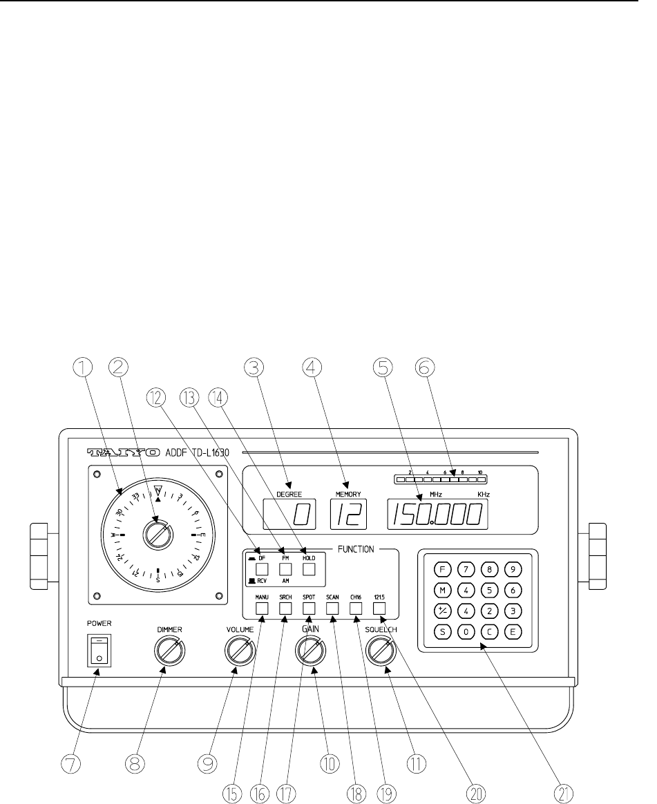
2.1.1 Front Panel
Fig.1 shows layout of keys and display devices on the front panel of TD-L1630.
Fig.1 Layout of keys and display devices on front panel
Instruction Manual of TD-L1630 Chapter 2
5
No. Name Functions
Ring display Relative bearing of a received signal is displayed in 10° step with 36 pcs. of LEDs
arranged in the circle.
Azimuth card True bearing can be read by rotating the azimuth card.
DEGREE display Relative bearing is displayed by numerals in 1° step.
It also shows entry condition with keyboard.
MEMORY display
The channel number of the memorized frequency is displayed.
Frequency display
A selected frequency is displayed in 5 kHz step.
Level indicator The signal strength is indicated with 10 LEDs.
Stronger electric field strength lights a lot of LEDs.
POWER switch Turn to “-“ position to power ON, and turn to “○” to power OFF.
DIMMER knob Rotate the knob clockwise to increase the brightness of LEDs and LCDs.
Also, pull the knob to illuminate a lamp on azimuth card.
VOLUME knob Rotate the knob clockwise to increase volume.
GAIN knob Rotate the knob clockwise to increase gain.
Please set gain maximum when measuring direction.
In SCAN or SRCH mode, it would be possible to receive only the strong signal (a signal
from short distance) by decreasing the gain.
SQUELCH knob Rotate clockwise to suppress noise when no-signal in AM and FM reception.
Note: Too much suppression may hinder reception of weak signal.
DF/RCV switch Press the button for DF mode, release it for RCV mode.
High sensitivity reception is possible at RCV mode, and direction finding is not possible
at RCV mode. In the RCV mode, nothing is indicated on Ring display and DEGREE
display.
FM/AM switch Press the button for FM reception, release it for AM reception.
HOLD button While it is ON, a bearing data is held until next signal comes.
MANU button Manual reception or, enter/renew a data by keyboard.
SRCH button Search over a frequency range, Fc (center frequency) ± 500 kHz in 5 kHz step.
SPOT button Call up a frequency with its channel number.
SCAN button Scan a group of frequencies (max. 10 frequencies in a group x 3 groups).
Scan stops when a signal is received. When the HOLD button is ON, bearing is
maintained until next signal reception.
CH16 button Press to receive international VHF channel number 16.
121.5 button Press to receive international distress signal 121.5 MHz.
F Frequency key. Enter a frequency. (MANU or SRCH mode)
M Memory key. Enter data in a memory. (SPOT, SRCH or SCAN mode)
+/- Up-down key.
Alter the number of frequency ascending or descending. (MANU or SRCH mode)
Change the 2nd digit of channel number when Memory key is ON.
S Start key. Use with a function key as follows.
Restart SRCH or SCAN. (SRCH or SCAN mode)
Change the frequency by 5 kHz step. (MANU mode)
Change the channel number by 1. (SPOT mode)
C Clear key to erase an erroneous input.
E Enter key to execute input command.
Keyboard
0 ~ 9 Numeric keys to enter number.
Instruction Manual of TD-L1630 Chapter 2
6
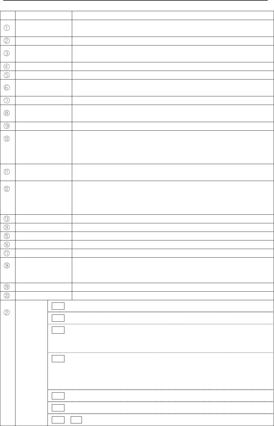
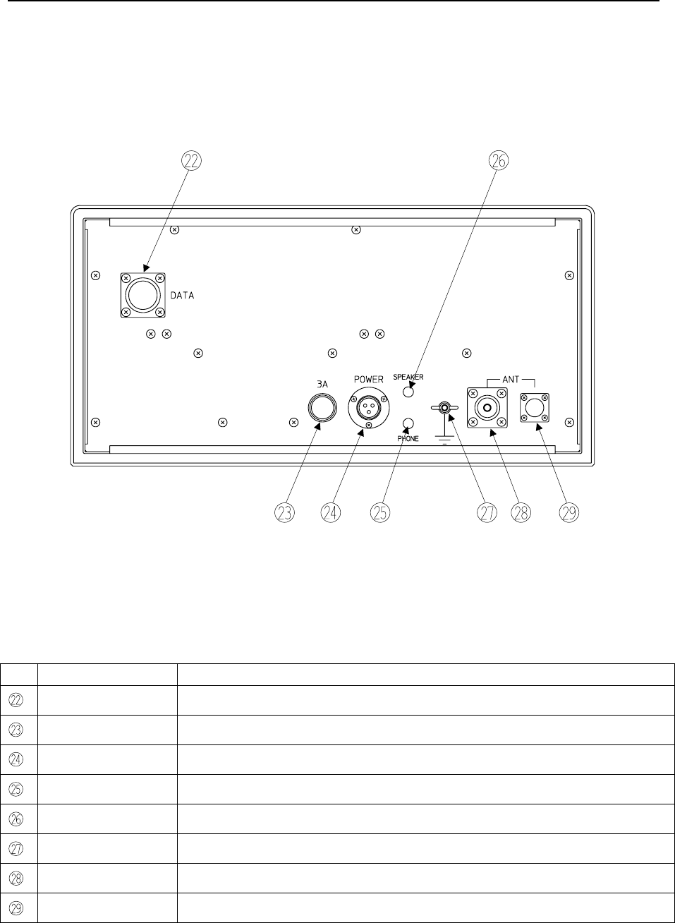
2.1.2 Rear Panel
Fig.2 shows layout of terminals on the rear panel of TD-L1630.
Fig.2 Layout of terminals on rear panel
No. Name Functions
DATA Data output terminal. See article 2.4 for the details of output data.
Fuse 3A Fuse holder contains a fuse MF60NR 250V 3A.
POWER Power connector for power cable.
SPEAKER Mini-jack to connect with a speaker (4Ω).
PHONE Mini-jack to connect with a earphone or headphone.
GND Ground terminal to connect to the ship’s ground terminal.
ANT left Antenna cable connector for M type connector.
ANT right Antenna cable connector for BNC connector.
Instruction Manual of TD-L1630 Chapter 2
7
2.2 PREPARATION
2.2.1 Power
(1) Confirm that a DC power 11V ~ 35V is supplied from a DC source.
If AC power source is supplied, use optional AC power supply unit TG-1637CS.
(2) Turn power switch on. All settings and adjustments at the last power off are restored.
For example, the unit starts and continues signal reception after power on with the same condition
as the unit was receiving before the last power off.
(3) Turn power switch off to terminate operation.
2.2.2 Frequency Memory
(1) Basic procedure to set a frequency (MANU mode)
A) Confirm that the MANU button is ON. If not, press MANU button.
B) Enter frequency, press F → Frequency, 6 digits → E
Note: Bearing display (DEGREE) blinks until E is pressed.
Example : Enter 136.740 MHz
F → 1 → 3 → 6 → 7 → 4 → 0 → E
Note: In case of mis entry, press C to clear, then enter the correct number.
Input frequency should be between 110.000 MHz and 169.995 MHz, 5 kHz step.
Erroneous input is not accepted.
Above procedures are rewritten as : MANU → F → Frequency, 6 digits → E
The unit starts reception when a frequency is set.
To set a frequency in step of 5 kHz when the unit is receiving a frequency in MANU mode.
Press S as many times as wanted. The frequency increases or decreases in step of 5 kHz.
(ascending or descending is selectable by pressing +/- key.)
(2) Enter the frequency in a memory
After setting a frequency by procedure (1), press M and set a channel number in the order of a
group number and a last digit, and finally, press E to enter the frequency in the memory
channel.
The basic procedures to enter a frequency in a memory channel is rewritten as:
MANU → F → Frequency → E → M → +/- → Last digit → E .
Note: There are 3 groups, with group numbers, 0, 1 and 2.
A channel number consists of a group number and a last digit.
For example, a channel number “26 “has a group number “2” and a last digit “6”.
136.740 13.674
. 1 1.367.136. 13

Instruction Manual of TD-L1630 Chapter 2
8
(3) Memory of a frequency in SRCH mode
When an interesting frequency is found in SRCH reception, hold that frequency by pressing
HOLD and enter it into the memory with a channel number by following procedures.
HOLD → M → +/- → Last digit → E .
(4) Enter a new SPOT frequency in an existing memory channel
Set a new frequency and enter the frequency to the memory channel. The old data is canceled by
overwriting.
(5) To erase all SPOT frequencies in the memory
A) Turn power switch off once.
B) Turn power switch on while pressing M , all frequencies in the memory are erased.
2.2.3 Mode Selection
(1) Select a mode of reception and a mode of modulation
A) Select the mode at first, MANU, SPOT, SRCH or SCAN, and press the key.
B) Check the mode of modulation, FM or AM. Press or release the FM/AM key when necessary.
(2) Select DF/RCV (this selection may be changed while in operation)
Reception only (RCV mode) is selected when release the DF/RCV key. DF mode is selected
when it is pressed, and both reception and bearing measurement are available. RCV mode is
usually selected when the level of signal is too weak to measure the bearing or wish to hear the
voice sound much clearly.
(3) Select HOLD (this selection may be changed while in operation)
There are two functions for hold, one is to keep the bearing data while there is no signal in MANU
or SPOT mode, and the other one is to lock the frequency in SRCH or SCAN mode.
A) Bearing data in MANU or SPOT mode (the frequency does not change)
When there is no signal, the bearing output fluctuates. When a signal is received,
instantaneous bearing data is displayed (data is continuously updated).
When the signal stops and HOLD is off, the bearing output fluctuates widely.
When the signal stops and HOLD is on, the bearing output keeps the last received data until
another signal comes.
B) Bearing data and frequency in SRCH or SCAN mode
When there is no signal, the bearing output fluctuates and frequency is automatically swept.
When a signal is received, frequency change stops and instantaneous bearing data is
updated every second.
When HOLD is off and the signal stops, the unit automatically restarts SRCH or SCAN sweep
and bearing output fluctuates.
When HOLD is on and the signal stops, the bearing output keeps the last data until another
signal comes and the frequency is locked. When another signal comes at that frequency, the
bearing data is updated. To restart SRCH or SCAN, press S .

Instruction Manual of TD-L1630 Chapter 2
9
2.2.4 Adjustment
(1) DIMMER
When the DIMMER knob is pulled, the azimuth card is illuminated. Rotate the knob clockwise to
raise brightness of LEDs and LCD.
(2) VOLUME
Rotate the volume clockwise to increase the loudness of the speaker.
(3) GAIN
Rotate the GAIN knob to elevate RF sensitivity.
(4) SQUELCH
Rotate the SQUELCH knob clockwise to suppress the audio noise when there is no signal.
(5) AZIMUTH (should be adjusted for true bearing measurement)
Rotate the AZIMUTH card according to the reading of the compass on board. The reading of LED
to the AZIMUTH card gives the true bearing of the radio signal. Since azimuth setting is manual,
AZIMUTH card should be rotated according to the compass reading when true bearing is required.
2.3 RECEPTION AND BEARING MEASUREMENT
2.3.1 Operation – MANU
(1) Basic procedure for manual reception
Confirm that MANU is ON. If not, press MANU key. Set a frequency and receive.
F → Frequency, 6 digits → E .
Note: a) When F is pressed, 000 blinks in DF mode at the bearing display (DEGREE).
b) The first digit should be 1, the second should be 1,2,3,4,5 or 6, and the last one should
be 0 or 5.
c) When an incorrect number is entered, press C and enter correct number.
d) The relative bearing is displayed in DF mode when a signal is received.
e) When there is no signal and HOLD is OFF, bearing data fluctuates.
f) When there is no signal and HOLD is ON, last bearing data remains.
(2) Change to another frequency in 5 kHz step while receiving in MANU mode.
S or +/- → S
Note: Press S as many times as necessary.
A press of +/- ascends/descends the frequency.

Instruction Manual of TD-L1630 Chapter 2
10
2.3.2 Operation – SPOT
(1) Basic procedure for spot reception
Confirm that SPOT is ON. If not, press SPOT key. Call up a channel and receive.
M → +/- → Last digit → E
Note: a) When M is pressed, 000 blinks in DF mode at the bearing display (DEGREE).
b) The relative bearing is displayed in DF mode when a signal is received.
c) When there is no signal and HOLD is OFF, bearing data fluctuates.
d) When there is no signal and HOLD is ON, last bearing data remains.
(2) Change to another channel in the same group while receiving in SPOT mode.
Press S as many times as necessary.
2.3.3 Operation – SRCH
(1) Basic procedure for search reception
Confirm that SRCH is ON. If not, press SRCH key. Set a center frequency, Fc.
When E is pressed, searching starts in step of 5 kHz in the range of Fc ± 500 kHz.
F → Center frequency, 6 digits → E
(2) Reverse the frequency sweep, press +/- .
(3) When a signal is received and frequency search stops, press S several times to find a
frequency at which the level indicator shows maximum.
(4) When an interesting frequency is found in SRCH reception, store it in a memory channel by
following procedure. HOLD → M → +/- → Last digit → E
(5) When HOLD is on, incoming signal locks frequency search. To restart search, press S .
2.3.4 Operation – SCAN
(1) Set SCAN mode
Confirm that SCAN is ON. If not, press SCAN key.
When SCAN mode was selected at the last power off, SCAN restarts when the power is turned on.
(2) Check the group number. To change the group number, operate key as following.
Press +/- a few times: M → +/- → E
(3) When HOLD is on, incoming signal locks frequency scan. To restart scan, press S .
(4) SCAN pass
When a frequency is not necessary to be scanned while it is being received, following procedure
restarts scanning and that frequency is skipped from the next scan: M → E → S
(5) A frequency returns to be scanned again from being scan-passed, enter the last digit of its channel
number by following procedure. M → Last digit → E

Instruction Manual of TD-L1630 Chapter 2
11
2.3.5 One-touch reception
There are tow one-touch reception button.
(1) Press 121.5 (red button) to receive international distress signal 121.5 MHz.
FM mode is automatically selected regardless the condition of FM/AM switch.
(2) Press CH16 (blue button) to receive international VHF channel 16.
AM mode is automatically selected regardless the condition of FM/AM switch.
This one-touch reception is effective at any time after power switch ON.
2.3.6 Bearing Measurement
(1) Bearing data relative to the bow direction is displayed while a signal is being received both on the
digital display in 1° step and on the ring display in 10° step.
(2) The relative bearing is updated every second, and a displayed value is an averaged one over a
second.
(3) When the true bearing (relative to the North direction) is necessary, read the bow direction on the
compass and rotate the azimuth card. Then the true direction is shown on the azimuth card.
Digital true bearing is calculated as the sum of the bow direction and the relative bearing.
Instruction Manual of TD-L1630 Chapter 2
12
2.4 DATA OUTPUT
There is a data output terminal on the rear panel to output frequency and bearing of received signal.
Pin assignment of data output terminal (connector: PRC04-21A16-14M)
Pin number Name of signal Signal contents Data format Interface
A OUT 1 + output NMEA0183 RS-422
B OUT 2 - output NMEA0183 RS-422
C ~ N Not used - - -
Specification of interface
Baud rate 4800 bps
Data bit 8 bit
Parity Non
Start bit 1 bit
Stop bit 1 bit
Forwarding data ASCII
Data format
Number Name of data Description Bite
1 Start code {$} 1
2 Device name {DF} 2
3 Sentence name {BRG} 3
4 Comma {, : HEX code 2C} 1
5 Comma {, : HEX code 2C} 1
6 Frequency 110,000,000 ~ 170,000,000 Hz 9
7 Comma {, : HEX code 2C} 1
8 Comma {, : HEX code 2C} 1
9 Bearing 000 ~ 359 deg 3
10 Comma {, : HEX code 2C} 1
11 Relative bearing {R} 1
12 Comma {, : HEX code 2C} 1
13 Comma {, : HEX code 2C} 1
14 Status {A : Valid, V : Invalid} 1
15 Comma {, : HEX code 2C} 1
16 Asterisk {* : HEX code 2A} 1
17 Check sum 00 ~ FF 2
18 End code {CR : HEX code 0D} 1
19 End code {LF : HEX code 0A} 1
Note: Check sum field is xOR of all 8 bit characters, and include {,} between {$} and {*} ({$} and {*} are excluded).
The value of the hexadecimal notation in four high rank bits and four subordinate position bits of the result is
converted into two ASCII characters
(
0-9,
A
-F
)
and transmitted.
$DFBRG,,XXXXXXXXX,,XXX,R,,X,*XX<CR><LF>
Frequency
Sentence name
Device name
Start code
Check sum End code
Asterisk
Status
Relative bearing
Bearing
Instruction Manual of TD-L1630 Chapter 3
13
Chapter 3 INSTALLATION
3.1 ANTENNA
3.1.1 Antenna Site
Following instructions shall be noted for antenna installation to minimize disturbance on direction
measurement, since the performance of a short wave direction finder is vulnerable to the influence of
conductive bodies nearby. (e.g., upper structure, stay cables, derricks and other antennas.)
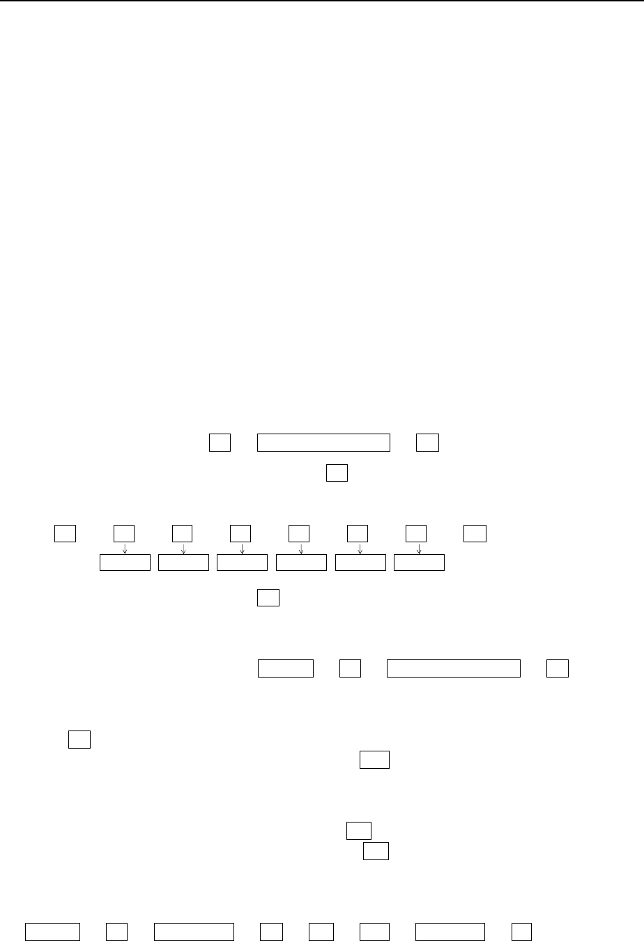
(1) The separation between the Adcock antenna
and the keel line shall be minimized.
(2) The top of the fore mast, radar mast or the
highest possible position is recommended to
install the Adcock antenna.
(3) The Adcock antenna shall be situated 2m or
higher from the TX/RX main antenna. Make
the horizontal separation larger than 2m from
the main antenna by inserting insulators.
The separation of Adcock antenna and the
navigation lamp shall be larger than 1m.
(Refer to Fig. 3 - A)
(4) The Adcock antenna shall be 1m or higher
than radar antenna and the horizontal
separation from a tip of radar antenna shall
be 0.8m or more. (Refer to Fig. 3 - B)
(5) Keep a horizontal separation of 2m or more
and vertical separation of 1m or more from a
perpendicular metallic object (metallic mast,
pole, etc.). If there is a metallic object
higher than the Adcock antenna, keep a
horizontal separation of 5m or more.
(Refer to Fig. 3 - C)
(6) When wire stays are used for the stanchion,
insert insulators 1m from the stanchion.
(Refer to Fig. 3 - D)
(7) When whip antenna or like is close to the
Adcock antenna, keep a vertical separation of
1m and a horizontal separation of 4m. When
such separation is impossible, tilt the whip
antenna. (Refer to Fig. 3 - E)
1m or more
0.8m or
more
Radar
scanner
Fig. 3 - B
Fig. 3 - C
1
m or
more
0
.75m or more
I
nsu
l
ator
S
tay w
i
re
Fig. 3 - D
1
m or more
4m or
more
Whi
p antenna
Fig. 3 - E
2m or more
Insulator
2m or more
TX/RX main
antenna
Fig. 3 - A
Navigation
lamp
2m or more
1m or
more
2
m or
more
5m or
more
Perpendicular
metallic object
Instruction Manual of TD-L1630 Chapter 3
14
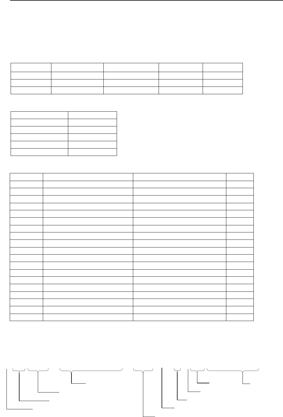
When an H type Adcock antenna is installed on board a small fishing boat 15m or smaller, please refer
to the following figure.
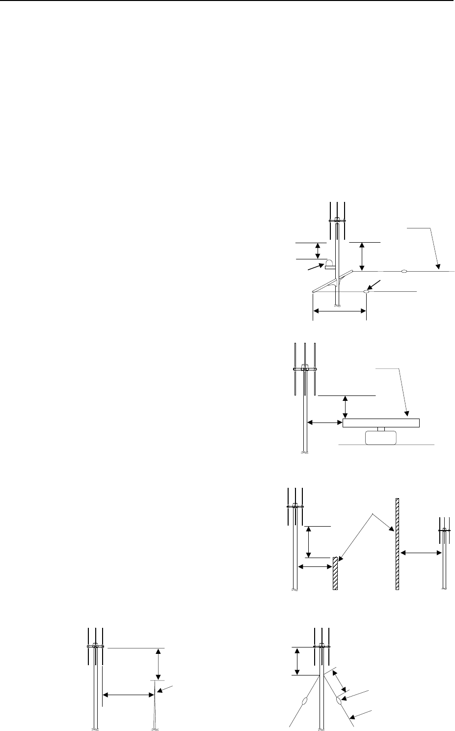
When a H type Adcock antenna is installed on board a fishing boat 20 ~ 30 m long or more, please
refer to the following figure.
5m or higher
A
dcock antenna
TX/RX whip
antenna
Fig. 4 -
A
5m or higher
A
dcock antenna
TX/RX whip
antenna Loop antenna for
HF/27MHz DF
Fig. 4 - B
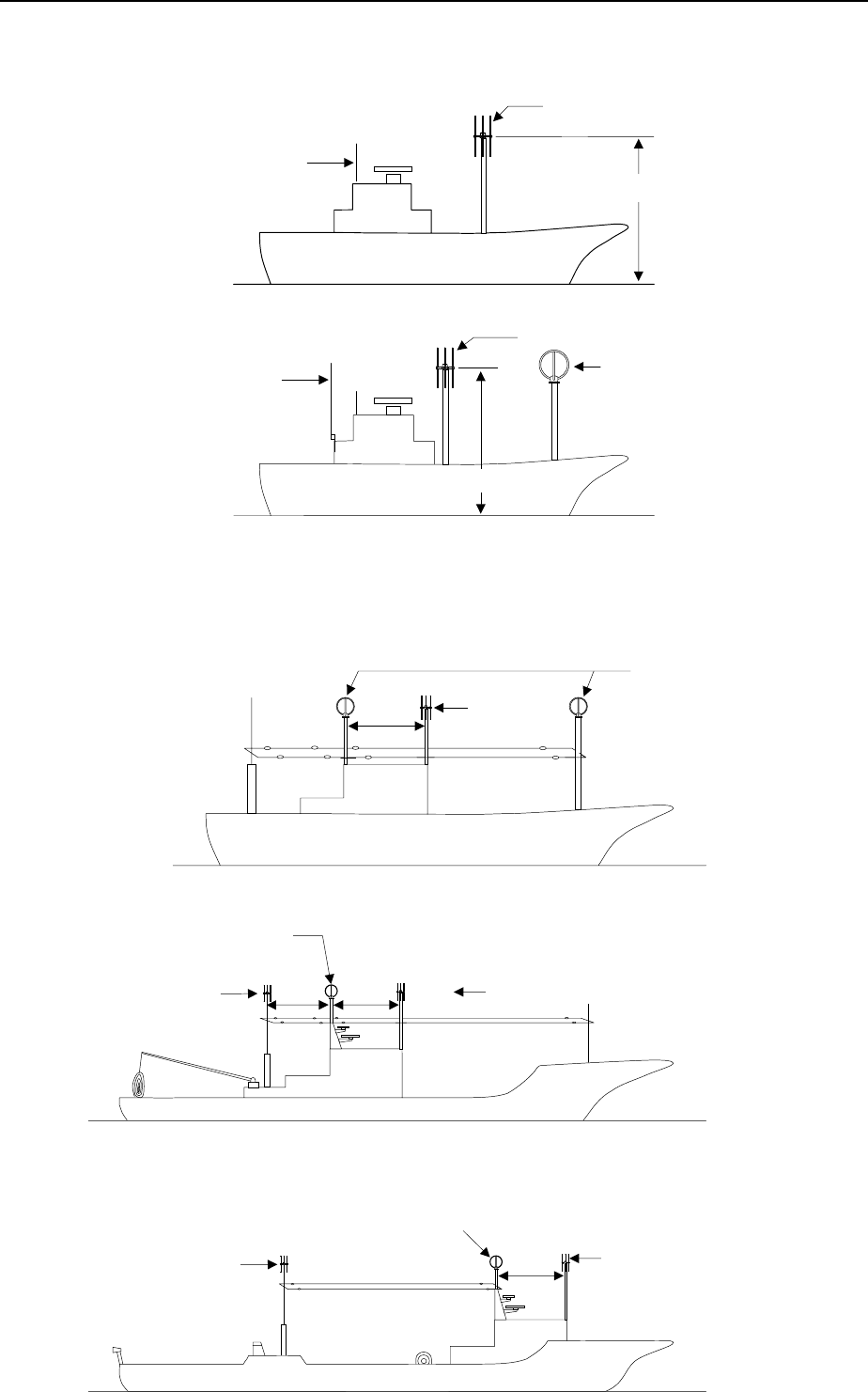
A
dcock
antenna
Loop antenna for
HF/27MHz DF
Fig. 5 -
A
4m or
more
Fig. 5 - B
4m or
more
A
dcock antenna
A
dcock
antenna
Loop antenna for
HF/27MHz DF
4m or
more
Fig. 5 - C
4m or
more
A
dcock antenna
A
dcock
antenna
Loop antenna for
HF/27MHz DF
Instruction Manual of TD-L1630 Chapter 3
15
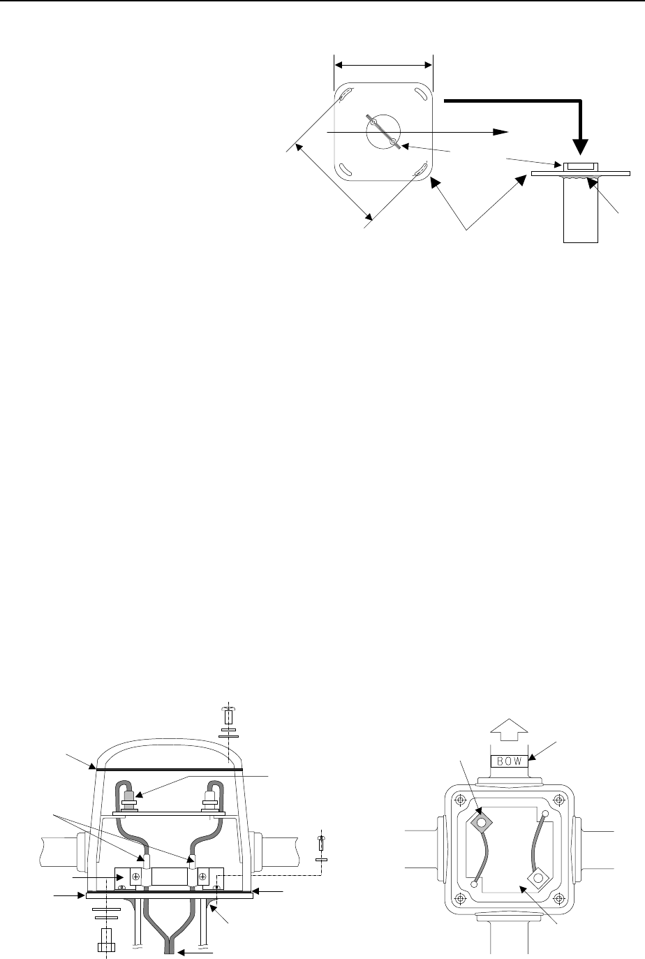
3.1.2 Flange
Weld a flange to a mast or a stanchion
by paying attention to its direction.
Work with care while welding, since the
antenna cable is not heat resistive.
3.1.3 Antenna Cable
(1) Keep separation from heat sources as the cables are not heat resistive.
(2) Protect the cables from mechanical damage. When inevitable, protect cable in steel or plastic pipe.
(3) Pay strict attention to welding after the cable has been laid.
(4) Avoid electromagnetic interference by keeping distance from power cables of other equipments.
(5) Never lay the cable along stays or other wires which may cause large error in bearing
measurement.
(6) Fix the cable length before shipment. Avoid to cut or elongate the cable because re-adjustment
of the main unit is required to change the cable length.
Note: Two RF coaxial cables (RG-58A/U) are required. One for balanced modulator output signal and the other for
sense signal. The sense signal cable is connected with BNC and M type plug. The balanced modulator cable is
connected with both BNC plugs. BNC plug with M type plug is painted with red. Any cable length is allowed, but
its sensitivity is affected by its length. The cable length is recommended as short as possible. The difference in
the length of the coaxial cables must be within ± 2 cm.
Fig. 7 Antenna Cable Connection
Rubber
packing
5NS-20
5SW
5W
Red pain
t
(BNC plug)
Clamp
mark
Cable clamp
Flange Rubber
packing
4NS-8
4SW
8W
8TW
8HS-20
Welding
Twin coaxial cable
Red paint
(BNC connector)
Matching
board
Point this BO
W
mark side to the
bow.
Bo
w
124 mm
136 mm
Flange Welding
BOW
Fig. 6
Cable
clamp
Instruction Manual of TD-L1630 Chapter 3
16
3.1.4 Installation of Antenna
Set the antenna on the flange welded at the selected position. Adjust its direction so that the
connection between N and S element is set in parallel to the keel line. Confirm that BOW mark is on
the bow direction. Pay attention to sea water or rain so that printed boards, connectors and so on in
the antenna are not wet or contaminated during the work.
3.2 MAIN UNIT
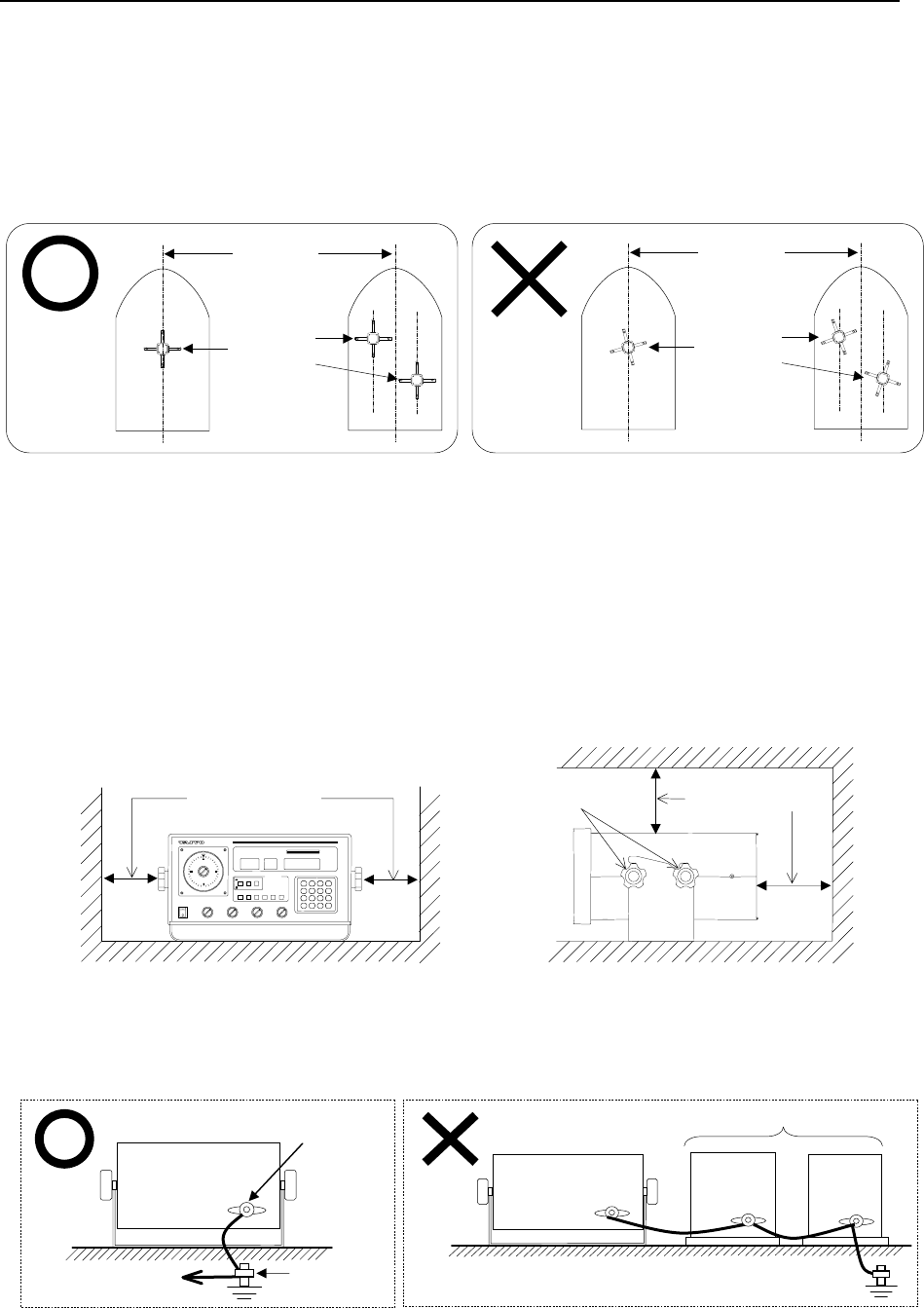
(1) Select a position (table, rack, etc.) for the main unit satisfying following conditions:
A) Convenient for operation, easy to maintain and with a good view of the display.
B) Avoid direct sunshine, water splash, high temperature and strong vibration.
C) Give a separation of 150 mm or more for both sides and back of the main unit.
(2) Grounding of the main unit shall be made with a low impedance cable, as short as possible, to a
grounding point of the vessel.
(3) Follow the procedures shown below to install the main unit.
A) Loosen two knobs combining the unit and its support and separate them.
B) Fix the support to a table, rack or like, with 6 screws (attached).
C) Fasten the main unit to the support with four Thumb screws.
Keel line
Adcoc
k
antenna
Keel line
Adcoc
k
antenna
Thumb screw 150mm or more
150mm or more
Ground
terminal
To GND terminal of
other equipment
Good example
Main uni
t
rear side
Other
No good example
Ship’s ground
terminal
Fig. 8

Instruction Manual of TD-L1630 Chapter 3
17
3.3 DESCRIPTION OF CIRCUIT
3.3.1 Antenna Circuit
The antenna is a H type Adcock antenna, and a sense signal is synthesized with signals from NS and
EW elements by special matching circuit. NS and EW signal are modulated by 135.6 Hz and the
output signal is fed to the main unit through coaxial cable A. The 135.6 Hz is supplied from PCA CPU
(appendix 7) through coaxial cable A and B. The sense signal is applied through coaxial cable B.
3.3.2 Printed Circuit Assemblies
(1) PCA HF
PCA HF involves super heterodyne circuits which are shown as following:
A) VHF Amp.
The antenna output are amplified by Q1 and Q2 and its both output are applied to Q3.
Q1 ~ Q6 and Q11 ~ Q12 are VHF amplifiers and the gain is controlled automatically.
The capacitor diodes in the tuning circuit are variable.
B) 1st Mixer
The 1st mixer, U1, generates a 1st IF in 30 ~ 30.995 MHz which is supplied from PCA VCO-1
(appendix 8).
C) 1st IF
The 1st IF 30 ~ 30.995 MHz is amplified by Q7, Q8 and Q9.
D) 2nd Mixer
U2 is the 2nd mixer which generates a 2nd IF of 21.4 MHz which is supplied from PCA VCO-2
(appendix 9).
(2) PCA IF/AF
PCA IF/AF is in charge of IF and AF circuits which are explained as following:
A) 2nd IF Amplifier
The 2nd IF, 21.4 MHz, is amplified by Q1 and Q2, and FL1 is a crystal filter of 21.4 MHz.
B) 3rd Local Oscillator
Q4 is the 3rd local oscillator and generates 20.945 MHz.
C) 3rd Mixer
Q3 is the 3rd mixer for 21.4 MHz and 20.945 MHz, the difference, 455 kHz.
D) 3rd IF Amplifier
The 3rd IF, 455 kHz, is amplified by Q5 ~ Q10, and the signal is detected by CR8, and applied
to ADDF amplifier circuit.
E) AGC, SQUELCH, AF, Amplifier
Q11 and Q12 are AGC amplifiers, which supply the AGC voltages to Q4, Q6 and Q9 of PCA
HF and Q2, Q7 and Q9 of PCA IF/AF. Q14, Q15 and Q16 are the other 455 kHz amplifier
and the amplified signal is detected by diodes CR9 and CR10 to detect FM signal. Q20 and
Q21 are squelch control, and Q22, Q23, Q24 and Q25 are audio amplifiers. Noise is
amplified by U1, Q26 and Q27. Its output voltage is applied to stop the scanning and to
control a squelch. Q17, Q18, Q19, Q30 and Q31 amplify the signal of 135.6 Hz ADDF. L2
and C79 make band pass filter for 135.6 Hz. Q13 is a level indicator amplifier and its gain is
adjusted by RV1 and RV2. Q28 and Q29 control a voltage for dimmer.

Instruction Manual of TD-L1630 Chapter 3
18
(3) PCA VCO-1
It has the 1st local oscillator with frequency synthesizer circuit, which generates 80 ~ 139 MHz.
U3, U4 and U5 are the programmable counter for MHz setting. U2 is a phase detector and Q1,
Q2 and Q3 are low pass filter circuits.
Q4, CR1 ~ CR4 and T1 consists of a VCO circuit. The circuit generates frequency and it is
amplified by Q5, Q6 and Q7. Then it is applied to the 1st mixer of PCA HF. U11 and U7 are
frequency divider for the programmable counter. Q8 is a buffer amplifier for the variable
capacitor diode of PCA HF.
(4) PCA VCO-2
It has the 2nd local oscillator with frequency synthesizer and generates 8.6 ~ 9.595 MHz. U3, U4
and U5 are the programmable counter for kHz setting. U10 is the phase detector and Q1, Q2
and Q3 are low pass filter circuits. Q4, CR1 ~ CR4 and T1 consists of a VCO circuit and the
circuit generates frequency and it is amplified by Q5, Q6 and Q7. Then it is applied to the 2nd
mixer of PCA HF.
(5) PCA CPU
The ADDF signal is applied from PCA IF/AF and the outputs are transferred to PCA DISPLAY and
LED to display bearing information, and all process is controlled by the CPU. The PCA includes
a master counter for bearing display, a basic frequency generator of 5 MHz, and encoder by key
board switch, a scanning control, a back up circuit for memory, a balanced modulator signal
generator, and the latch for the display. U12, U13, U14, U8, U17, U18 and U15 are CPU circuits.
U20 is the master counter, and 135 Hz, 270 Hz and 540 Hz are generated from the master
counter and are applied to PCA BM. Q1, Q2 and Q3 are the back-up battery over circuit.
(6) PCA NMEA
This PCA composes the RS-422 interface, and is used for the data output.
(7) PCA Display
The PCA consists of the key board switch, and LCD display circuits.
(8) PCA LED
The PCA consists of the bearing indicator with 10° step on the LED display.
(9) PCA Chopper
The PCA is a voltage regulator.
Input voltage allows from 11V to 35V and output voltage is regulated to 9V by chopper control
circuit.
(10) PCA AVR (appendix 11)
This PCA is on the rear side of chassis, and it consists of 3 voltage regulators, 5V, 5V and 30V for
computers.
(11) PCA BM
The PCA supplies 4 phase balanced modulator signal.
(12) PCA Noise Limiter
The PCA consists of a noise limiter circuit and Q1 is an audio amplifier.
(13) PCA Switch 1
This PCA is composed of the switch that switches the function.
(14) PCA Switch 2
This PCA is composed of the switch and the relay that switches the function.

Instruction Manual of TD-L1630 Chapter 3
19
3.4 PERFORMANCE CHECK AND REPLACEMENT
3.4.1 Test Equipment
Performance check of the direction finder requires following test equipment.
(1) Antenna Simulator
(2) Signal Generators
It shall cover 400 kHz to 200 MHz with variable output up to 1V, and within output impedance of
50Ω.
(3) Others
(a) HF voltmeter
A voltmeter with high input impedance for 150 MHz and to have 10mV ~ 3V range.
(b) Frequency counter
(c) AC voltmeter
(d) Oscilloscope
(e) Multimeter (DC 20 kΩ/V)
(f) DC power supply 24V DC, 2A
3.4.2 Test Arrangements
(1) VHF Check
The overall test shall be carried out on VHF by the arrangements as shown in Fig. 9 and the
following test procedures.
Step Procedure Normal condition
1. Connect equipments as shown in Fig.9.
Apply 24V DC to the equipment.
9.2V DC is applied to the amplifier
circuit of PCA IF/AF.
2.
2-1
2-2
2-3
2-4
2-5
2-6
Switch ON NS of TM-643.
Signal generator to 145.5 MHz, 1000Hz, 3.5
kHz DEV.
TD-L1630, Turn power switch ON.
Select DF mode.
SQUELCH to counterclockwise to the end.
Rotate GAIN and VOLUME clockwise to the
end.
Set the signal generator output 60 dB (1mV).
Set frequency to 145.5 MHz and switch ON NS
and V of TM-643.
LCD display is lit.
Noise tone is heard from the speaker.
The bearing shall be 0° ± 3°.

Instruction Manual of TD-L1630 Chapter 3
20
2-7
2-8
2-9
Switch ON EW of the TM-643.
Switch OFF NS of the TM-643.
Set the signal generator output 36dB.
The bearing shall be 45° ± 3°.
The bearing shall be 90° ± 3°.
The bearing shall be 90° on 1µV/m.
3.
3-1
3-2
3-3
3-4
3-5
3-6
Connect the signal generator output to M type
connector of ANT directly, and set the mode
switch RCV.
Set the signal generator to 145.5 MHz, CW.
Same as 2-3.
Same as 2-4.
Adjust the VOLUME so that the speaker output
become 1.0V when no output from signal
generator.
Set the signal generator output to 6 dB, and
confirm that the speaker output is less than
0.1V.
Signal Generator
Antenna
Simulator TM-643
AC
voltmeter
24V DC
power
TD-L1630
Fig. 9 Test Arrangement
Speaker
M type connector
BNC connector
Instruction Manual of TD-L1630 Chapter 3
21
(2) Test of frequency synthesizer as the 1st local oscillator (PCA VCO-1)
(a) Test Procedure
When a trouble is in the frequency synthesizer, check as follows:
Set the receiving frequency to 110 MHz.
(i) To measure the standard frequency 25 kHz, connect a frequency counter to 1 pin of
U2 MC4044 and ground.
(ii) Connect a multimeter to TP3 (collector of Q2) and the ground. Measured voltage is
about 2.5V DC. The voltage is adjusted with the dust core of T1.
(iii) Connect a HF voltmeter to TP2 (secondary of T2) and the ground. It is normal when
0.16V r.m.s. is measured.
(iv) Connect the multimeter to TP1 (source of Q8) and the ground.
Normal value is about 4.1V.
(v) Connect the frequency counter to TP2 (secondary of T2).
The frequency is 80 MHz. When the frequency is deviated, adjust it by CV1 on PCA
CPU.
(b) Set the receiving frequency to 169 MHz, and measure following points
TP1 TP2 TP3
Voltage 15.1V DC 0.05V r.m.s. 15.5V DC
Frequency 139 MHz
Phase Detector Frequency
Divider
Programmable
Counter
Low Pass Filter VHF AMP VCO
TP1 TP2
V - G F2 - 0
From PCA CPU
25 kHz Fre
q
uenc
y
Data
(
BCD
)
Tuning Control
V (TP1) : 4.1 ~ 15.1V DC
V (TP3) : 2.5 ~ 15.5V DC
1s
t
Local Oscillator
F (TP2) : 80 ~ 139 MHz
V (TP2) : 0.05 ~ 0.16V r.m.s.
Fig. 10 Schematic diagram of PCA VCO-1

Instruction Manual of TD-L1630 Chapter 3
22
(3) Test of frequency synthesizer as the 2nd local oscillator (PCA VCO-2)
When a trouble is in the frequency synthesizer, check as follows:
(a) Set the receiving frequency to110 MHz.
(i) Connect the frequency counter to 1 pin of U10, MC4044, and measure the standard
frequency 5 kHz.
(ii) Connect the multimeter to TP2 (collector of Q2) and the ground, and the measured
voltage is about 2.6V DC, which is normal.
The voltage is adjusted with the dust core of T1.
(iii) Connect a AC voltmeter to TP1 (secondary of T2) and the ground.
OK when the voltage is circ. 0.2V r.m.s.
(iv) Connect a frequency counter to TP1 (secondary of T2) and the ground.
OK when the measured frequency is 8.6 MHz.
(b) Se the receiving frequency to 110.995 MHz.
Measure voltage on TP1 or TP2 and frequency at TP1.
The values are as follows:
TP1 TP2
Voltage Circ. 0.2V r.m.s. Circ. 3.9V DC
Frequency 9.595 MHz
Phase Detector Programmable
Counter
Low Pass Filter VHF AMP VCO
TP2
TP1
F1 – F2
From PCA CPU
25 kHz Fre
q
uenc
y
Data
(
BCD
)
V (TP2) : 2.6 ~ 3.9V DC 2nd Local Oscillator
F (TP1) : 8.6 ~ 9.595 MHz
V (TP1) : 0.3V r.m.s.
Fig. 11 Schematic diagram of PCA VCO-2

Instruction Manual of TD-L1630 Chapter 3
23
3.4.3 Replacement and Re-adjustment
(1) Re-adjustment of PCA IF/AF
All IF amplifier circuits are tuned at their center frequencies to get the maximum gain. Therefore,
shunt resistors for many coils shall not be changed. The following table gives standard level of
the IF circuit.
Transistor Input (dB mV) Frequency
Q1
Q3
Q5
Q6
Q8
Q10
25
45
62
38
63
78
21.4 MHz
455 kHz
455 kHz
455 kHz
455 kHz
455 kHz
* The output voltage 0.2V r.m.s. on secondary of T9 and GAIN is set to the minimum position.
(2) Re-adjustment of PCA HF
(a) T2, T3, T4 and T5 are tuned at 115 MHz and RV2/RV3 are adjusted at 165 MHz to get the
maximum gain, connecting the signal generator directly to J2 (BNC), and 50Ω (47Ω) resistor
to the J1 (M type).
Repeat above procedures 3 ~ 4 times.
Finally, rotate the adjuster of T2 for one revolution clockwise.
(b) VHF amplifier circuit T1 is tuned at 115 MHz, and RV1 is adjusted at 165 MHz to get
maximum gain, connecting the signal generator directly to J1 (M type connector) and 50Ω (or
47Ω) resistor to the J2 (BNC connector).
Repeat above procedures 3 ~ 4 times.
The following table gives standard level of the PCA HF.
Transistor Input (dB mV) Frequency
Q1
Q2
Q3
Q5
Q7
Q8
Q10
3
5
11
21
6
20
21
14.5 MHz
14.5 MHz
14.5 MHz
14.5 MHz
30.5 MHz
30.5 MHz
21.4 MHz
* The output voltage 0.2V on secondary of T9 on PCA IF/AF, and GAIN is set to the minimum position.
(3) Re-adjustment of voltage regulator
The output voltage of voltage regulator shall be adjusted to 9.2V with a variable resistor RV1 on
the PCA Chopper.
(4) Phase adjustment
Connect the antenna simulator as shown in Fig. 9.
Set the frequency and apply 145.5 MHz 65 dB from the signal generator. Switch NS and V to ON
the antenna simulator to get indicate 0° of digital display adjusting RV3 on the PCA IF/AF. Check
45° and 90° switching NS and EW to ON and NS to OFF, EW to ON.
Instruction Manual of TD-L1630 Chapter 3
24
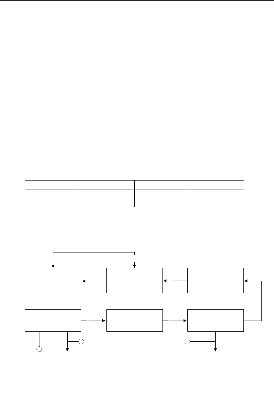
3.5 PROCEDURE OF PHASE ADJUSTMENT
When the TD-L1630 is installed under improper environmental conditions at shore station or land
station, the disturbance and/or some other harmful phenomenon may happen. Depends on the scale
of disturbance, phase adjustment is required, otherwise low receiving sensitivity and/or malfunction of
direction indication may be caused in TD-L1630. To avoid this situation, make some 10 cm length of
extension cables with connectors beforehand, and make an adjustment with following procedure to a
good phase status by adding the extension cable for either vertical cable or loop cable.
(1) Prepare some 10 cm length of extension coaxial cables (e.g. 10 cm, 20 cm, 30 cm, 40 cm. . . .
Since wave length of 150MHz is 2 m, it is better to prepare 10 kinds of extension cable from 10 cm
to 100 cm at 10 cm steps.) with M type connectors. (Refer to Fig. 12)
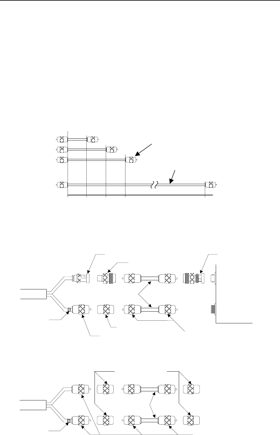
(2) Connect an extension cable in between V cable (vertical cable) of antenna cable first.
Use M-A-JJ connectors. Refer to Fig. 13-A and 13-B
M type connecto
r
(both sides)
Coaxial cable
10 cm 20 cm 30 cm 100 cm Fig. 12
Antenna cable type:
RG-58A/U BNCJ-MJ-A type connector
L (Loop)
V (Vertical)
Red Mark
Extension cable
BNC type connector BNCP-MJ-A type connector
L (Loop)
V (Vertical)
M type connector
Fig. 13 -
A
M type connector
M-A-JJ type connector
Antenna cable type:
5D-2V or 8D-2
V
Fig. 13 - B
Red Mark
M-A-JJ type connector
Extension cable
M type connector
Instruction Manual of TD-L1630 Chapter 3
25
(3) Put a probe of oscilloscope on TP terminal of PCA IF/AF to check if the modulation wave is good.
PCA IF is installed on the tail side of PCA CPU in the main unit.
(Refer to Fig.15)
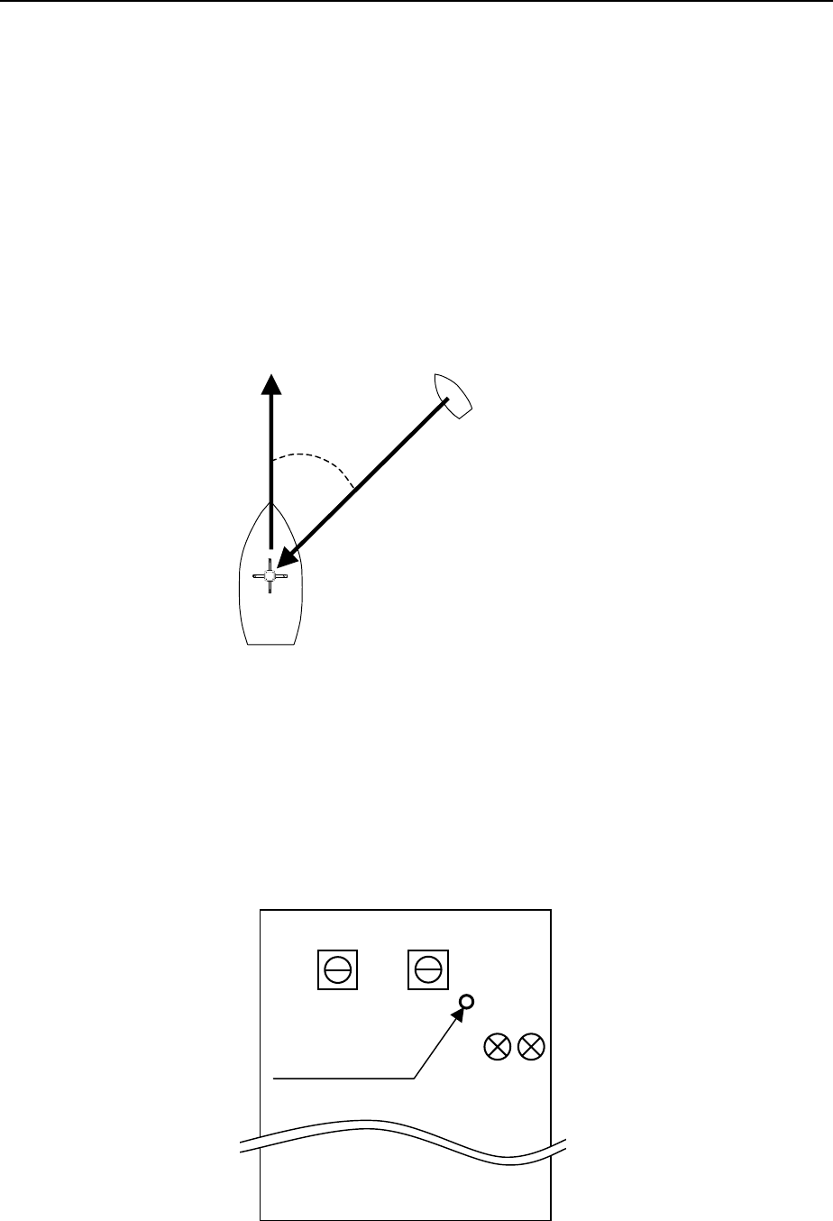
(4) Arrange a boat equipped with a VHF transmitter at 45 degrees against bow of the ship which
installed the TD-L1630, and transmit VHF signal. (Refer to Fig.14)
At that time, both ships shall cast an anchor to do not move.
TP
T8 T9
RV1 RV2
A
3042
Put a probe o
f
oscilloscope
on TP terminal
Fig. 15
PCA IF
Ship installed with TD-L1630
Boat equipped with
a VHF transmitter
Transmit a signal
within 110 ~ 169.995 MHz
Fig. 14
BOW
45°
Instruction Manual of TD-L1630 Chapter 3
26
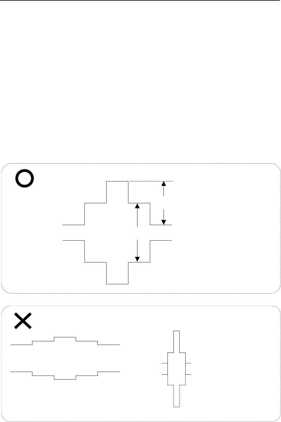
(5) Change the length of extension cable so that the ratio of BM wave form between vertical and loop
shall be in the ratio ranging between 1 (V) : 1 (L) and 3 (V) : 1 (L), when TD-L1630 receives
transmitting radio wave from 45 degrees of heading. (Refer to Fig.16)
Caution: If radio emission source is not 45 degrees from the heading of mother ship, shape of
Balanced Modulation Wave (Fig.16) is displayed on the oscilloscope improperly. Be sure to
set the radio emission source at 45 degrees from the heading of mother ship.
(6) If the phase status is not good even adjusted by extension cable, pull out every extension cable(s)
from V cable and connect it in between L cable (Loop cable; Refer to Fig.13-A, 13-B) instead.
Then, make an adjustment so that the ratio of BM wave form between vertical and loop shall be in
the ratio ranging between 1 (V) : 1(L) and 3 (V) : 1 (L), when TD-L1630 receives transmitting radio
wave from 45 degrees of heading.
(7) Make sure that DF measurement can be done with good accuracy of direction angle.
Good
L
V
Normal
modulation wave
V/L = 1:1 ~ 3:1
V
is too large:
Use longer extension cable for
V (vertical) cable.
Lis too large:
Use longer extension cable
for L (Loop) cable.
Fig. 16 Balanced modulation wave
No Good

Instruction Manual of TD-L1630 Chapter 4
27
Chapter 4 MAINTENANCE
The equipment is designed to have a high reliability and long life. However, both mechanical and short
electrical check is recommended once a year to prevent troubles.
If the environmental condition is severe, such as high temperature/humidity, strong vibration, large variation
in power supply and etc., shorten the period between checks in half or shorter.
In case it is inconvenient to check operations at its position, draw the main unit forward after loosening its
knobs.
When a trouble occurs or a failure is found, try electrical check. Then follow the trouble-shooting
procedures in this chapter. When the trouble can not be fixed, consult your agent or the manufacturer,
Taiyo Musen Co., Ltd.
4.1 MECHANICAL CHECK
4.1.1 Antenna
(1) Check tilt, bend, damage or erosion of antenna elements, element holders and stanchion.
(2) Check slackness, damage or breakage of cables and cable holders.
4.1.2 Main Unit
(1) Check damage or breakage of main unit.
(2) Check slackness, damage or breakage of cables and connectors
4.2 ELECTRICAL CHECK
4.2.1 Ni-Cd Battery for Backup Memory
The frequencies memorized in the memory are maintained by an electric power of the built-in Nickel
Cadmium (Ni-Cd) backup battery.
The Ni-Cd battery is automatically re-charged while the power of the main unit is ON.
When the equipment is operated for the first time, or not operated over one month or replaced the Ni-Cd
battery with the new one, keep the power “ON” for more than 15 hours to charge the back-up battery.
Data in memory would fade away when the Ni-Cd battery is completely discharged. In that case, enter the
data again after re-charge or replace the battery.
4.2.2 Fuse
When the fuse blows while in operation, a trouble in circuit is suspicious. Check and shoot the cause.
Afterwards, replace the fuse with a new MF60NR 250V 3A fuse.
CAUTION
C-MOS ICs are used in the equipment and hence, transient phenomena accompanied with
break in circuit may harm them. Therefore, cut off power supply and turn its power switch
off while in mechanical check, before electrical check and while changing parts and PCAs.

Instruction Manual of TD-L1630 Chapter 4
28
4.3 TROUBLE SHOOTING
4.3.1 Troubles and Countermeasures
When a trouble has occurred, try to find the category of trouble shown in Table 3 and take a
countermeasure to solve the trouble accordingly. When it is not successful by a countermeasure, ask
the agent supplied the system or directly to Taiyo Musen Co., Ltd. with following information:
Table 3. Symptom of troubles, their causes and countermeasures
Symptom of troubles Probable cause Countermeasure
Trouble in power cable / connector Ask replace or repair
Failure of power switch Ask for repair
No power supply and hence, any
operation is impossible Fuse has blown away Replace fuse with new one
Bad contact of switch Ask for repair
Bad connection of internal connector(s) Confirm connection
Breaking of wire inside Ask for repair
Failure in PCA Ask for replace or repair
Key or switch does not function
Bad contact at connection of PCA CPU
and PCA Display
Separate them once and insert
firmly
DC power is not supplied to the receiver Check fuse
Defective power plug or interconnecting
cord Check conductance of power line
Misconnection of polarity of the power
line Check the polarity
Complete silence on all frequency in
all mode. Indicator does not work
Defective receiver Remove receiver for test
Defective audio volume control Measure the resistance
Defective audio circuit
Make voltage measurement of
Q22 ~ Q25 on PCA IF/AF
Defective speaker Check conductance
No audio output
Defective squelch circuit Make voltage measurement of
Q20, Q21, Q26 & Q27 on PCA
IF/AF
Interference from outside source
Shut off engine and other electric
equipments except TD-L1630
Poor ground connections Check a ground connection
Noisy reception
Defective antenna cable Check conductance
Defective mode switch Check conductance
Poor “RCV” and normal “DF” Defective audio circuit Check audio circuit
A
) Model name, i.e. TD-L1630
B) Version number and check sum.
C) Symptom

Instruction Manual of TD-L1630 Chapter 4
29
Defective 135.6 Hz output circuit Make voltage measurement J1
and J2
Defective ADDF amplifier circuit Make voltage measurement of
Q17 ~ Q31 on PCA IF/AF
Defective PCA CPU Replace the PCA CPU
Defective PCA DISPLAY Replace the PCA DISPLAY
Defective balanced modulator circuit in
the Adcock antenna Check diode and transformer
Defective antenna cable Check conductance
Poor “DF” and normal “RCV”
(continued)
Defective mode switch Check conductance
Poor sensitivity in all mode and all
frequency Defective IF amplifier circuit Measure gain value
Defective antenna cable Check conductance Indicator shows always 0° or 90° (or
those opposite angle) Defective 135.6 Hz output circuit Measure the voltage of J1 & J2
The bearing error occurs in a certain
specific azimuth regardless of the
frequency
Defective phase adjustment Check RV3 on PCA IF/AF
Table 4. Voltage Measurement
PCA Circuit No. C (D) [volt] B (G) [volt] E (S) [volt]
PCA HF
Q1
Q2
Q3
Q4
Q5
Q6
Q7
Q8
Q9
Q10
Q11
Q12
3.9
2.5
4.1
7.8
4.2
8.6
8.2
3.9
7.6
8.2
6.2
0
0
0
0
5.6
1.3
5.6
1.5
1.2
5.6
1.5
4.6
0.8
0
0
0
4.8
0.5
4.9
0.8
0.5
4.5
0.8
3.9
0
PCA IF/AF
Q1
Q2
Q3
Q4
Q5
Q6
Q7
Q8
Q9
Q10
Q11
Q12
Q13
Q14
Q15
Q16
Q17
Q18
Q19
3.9
7.5
8.3
3.2
7.2
4.8
7.5
4.9
8.3
7.3
6.6
9.1
0.8
3.4
6.4
3.8
7.5
7.4
7.3
1.4
5.6
1.5
1.5
2.1
1.5
5.6
1.4
5.6
1.9
0.8
6.6
5.7
1.4
3.5
1.2
1.3
1.4
2.6
0.7
4.4
0.9
0.9
1.4
0.8
5.0
0.8
5.0
1.2
0.2
5.9
6.3
0.8
4.5
0.7
0.6
0.8
1.9

Instruction Manual of TD-L1630 Chapter 4
30
PCA IF/AF
(continued)
Q20
Q21
Q22
Q23
Q24
Q25
Q26
Q27
Q28
Q29
Q30
Q31
3.3
6.6
6.0
4.8
9.1
0
0
2.4
9.1
9.0
3.3
3.3
0.4
3.3
2.0
1.4
5.9
4.8
0.7
0
8.3
7.6
1.6
1.7
0
2.7
1.4
0.8
5.3
5.3
0
0
7.6
7.0
1.0
1.0
PCA VCO-1
Q1
Q2
Q3
Q4
Q5
Q6
Q7
Q8
26.0
10.3
10.3
5.8
4.8
4.8
4.9
30.0
1.3
1.3
0.7
0
0
0
1.5
10.2
1.3
0.7
0
0.5
0.5
0.5
0.7
10.4
PCA VCO-2
Q1
Q2
Q3
Q4
Q5
Q6
Q7
Q8
6.8
3.3
3.3
6.8
6.8
6.8
6.8
1.6
1.5
1.2
0.7
0
0
3.4
2.0
0.8
1.2
0.7
0
1.9
0.5
3.8
1.3
0.3
PCA Noise Limiter Q1 2.7 2.1 1.5
PCA BM
Q1
Q2
Q3
Q4
Q5
Q6
Q7
Q8
Q9
Q10
Q11
Q12
4.5
4.5
4.5
4.5
0
9.1
0
9.1
0
9.1
0
9.1
0.35
0.35
0.35
0.35
4.5
4.5
4.5
4.5
4.5
4.5
4.5
4.5
0
0
0
0
4.5
4.5
4.5
4.5
4.5
4.5
4.5
4.5
PCA Chopper Q1
Q2
Q3
23.8
9.7
0
9.7
23.8
9.3
9.3
23.8
9.3
PCA AVR Q1 0 4.6 4.6
PCA CPU
Q1
Q2
Q3
Q5
Q6
5.0
0
5.0
5.1
5.1
4.3
0.7
0
2.5
2.5
5.1
0
0
1.8
1.8
Measurement condition : Use a Multimeter
Frequency 145.5 MHz
Power voltage 24V DC
Set the knob and switch position as follows:
GAIN : Maximum
FM/AM : FM
DF/RCV : DF

Instruction Manual of TD-L1630 Chapter 4
31
4.4 Remarks
The SW1 on PCA BM is used for special case such as installing on a aircraft.
Normally it must be set to “NOR” position.
4.5 Disposal
Follow local regulations to dispose the equipment.
Recycling of Ni-Cd battery is advised. It is soldered on PCA CPU and easily removed by cutting its
lead wire with a nipper. Apply insulation tape to its ends to prevent short circuit.