MITSUBISHI Projection/Digital 42 And Above TV Manual L0208263
User Manual: MITSUBISHI MITSUBISHI Projection/Digital 42 and above TV Manual MITSUBISHI Projection/Digital 42 and above TV Owner's Manual, MITSUBISHI Projection/Digital 42 and above TV installation guides
Open the PDF directly: View PDF ![]() .
.
Page Count: 79
_MITSUBISHI
THE BIG SCREEN COMPANY _"
RISK OF ELECTRIC SHOCK
DO NOT OPEN
CAUTION: TO REDUCE THE RISK OF ELECTRIC SHOCK, DO NOT REMOVE
COVER (OR BACK).
NO USER SERVICEABLE PARTS INSIDE.
REFER SERVICING TO QUALIFIED SERVICE PERSONNEL.
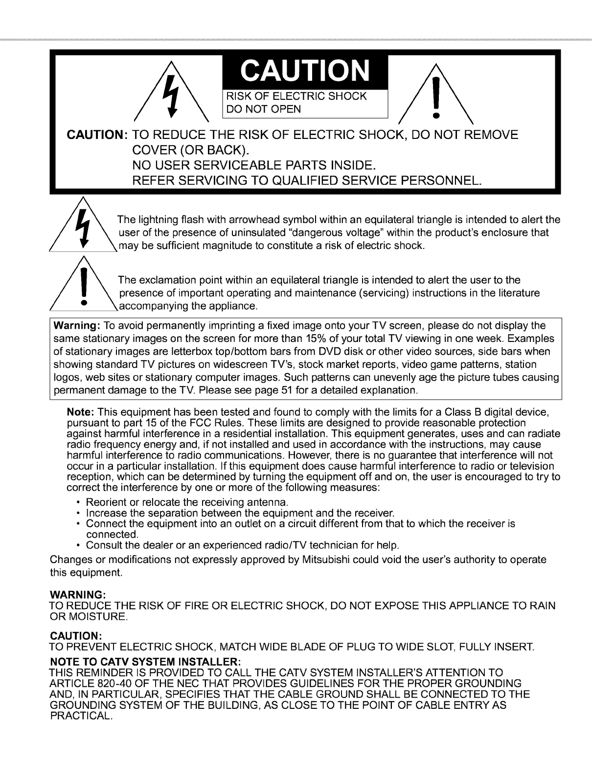
The lightning flash with arrowhead symbol within an equilateral triangle is intended to alert the
user of the presence of uninsulated "dangerous voltage" within the product's enclosure that
may be sufficient magnitude to constitute a risk of electric shock.
The exclamation point within an equilateral triangle is intended to alert the user to the
presence of important operating and maintenance (servicing) instructions in the literature
panying the appliance.
Warning: To avoid permanently imprinting a fixed image onto your TV screen, please do not display the
same stationary images on the screen for more than 15% of your total TV viewing in one week. Examples
of stationary images are letterbox toplbottom bars from DVD disk or other video sources, side bars when
showing standard TV pictures on widescreen TV's, stock market reports, video game patterns, station
Iogos, web sites or stationary computer images. Such patterns can unevenly age the picture tubes causing
permanent damage to the TV. Please see page 51 for a detailed explanation.
Note: This equipment has been tested and found to comply with the limits for a Class B digital device,
pursuant to part 15 of the FCC Rules. These limits are designed to provide reasonable protection
against harmful interference in a residential installation. This equipment generates, uses and can radiate
radio frequency energy and, if not installed and used in accordance with the instructions, may cause
harmful interference to radio communications. However, there is no guarantee that interference will not
occur in a particular installation. If this equipment does cause harmful interference to radio or television
reception, which can be determined by turning the equipment off and on, the user is encouraged to try to
correct the interference by one or more of the following measures:
• Reorient or relocate the receiving antenna.
• Increase the separation between the equipment and the receiver.
• Connect the equipment into an outlet on a circuit different from that to which the receiver is
connected.
• Consult the dealer or an experienced radiolTV technician for help.
Changes or modifications not expressly approved by Mitsubishi could void the user's authority to operate
this equipment.
WARNING:
TO REDUCE THE RISK OF FIRE OR ELECTRIC SHOCK, DO NOT EXPOSE THIS APPLIANCE TO RAIN
OR MOISTURE.
CAUTION:
TO PREVENT ELECTRIC SHOCK, MATCH WIDE BLADE OF PLUG TO WIDE SLOT, FULLY INSERT.
NOTE TO CATV SYSTEM INSTALLER:
THIS REMINDER IS PROVIDED TO CALL THE CATV SYSTEM INSTALLER'S ATTENTION TO
ARTICLE 820-40 OF THE NEC THAT PROVIDES GUIDELINES FOR THE PROPER GROUNDING
AND, IN PARTICULAR, SPECIFIES THAT THE CABLE GROUND SHALL BE CONNECTED TO THE
GROUNDING SYSTEM OF THE BUILDING, AS CLOSE TO THE POINT OF CABLE ENTRY AS
PRACTICAL.
IMPORTANT SAFEG UARDS ............................................................................. 4-5
Appendix A: Bypassing the V-Chip Lock ........................................................................................................... 66
Appendix B: High Definition Inputs Connection Compatibility ....................................................................... 67
Appendix C: Remote Control Programming Codes .......................................................................................... 68
Appendix D: Cleaning and Service ..................................................................................................................... 69
Appendix E: Diamond Shield Installation and Removal ............................................................................. 70-71
Appendix F: Cabinet Separation Procedure ................................................................................................. 72-73
Appendix G: Troubleshooting ........................................................................................................................ 74-75
Index ................................................................................................................................................................. 76-77
Mitsubishi Projection TV Limited Warranty ....................................................................................................... 78
IMPORTANT SAFEGUARDS
LPlease read the following safeguards for your TV and retain for future reference.
_Always follow all warnings and instructions marked on the television.
.
.
.
.
.
Read, Retain and Follow All Instructions
Read all safety and operating instructions before operating the TV. Retain the safety and operating instructions
for future reference. Follow all operating and use instructions.
Heed Warnings
Adhere to all warnings on the appliance and in the operating instructions.
Cleaning
Unplug the TV from the wall outlet before cleaning. Do not use liquid, abrasive, or aerosol cleaners. Cleaners
can permanently damage the cabinet and screen. Use a lightly dampened cloth for cleaning.
Attachments and Equipment
Never add any attachments and/or equipment without approval of the manufacturer as such additions may
result in the risk of fire, electric shock or other personal injury.
Water and Moisture
Do not use the TV where contact with or immersion in water is possible. Do not use near bath tubs, wash
bowls, kitchen sinks, laundry tubs, swimming pools, etc.
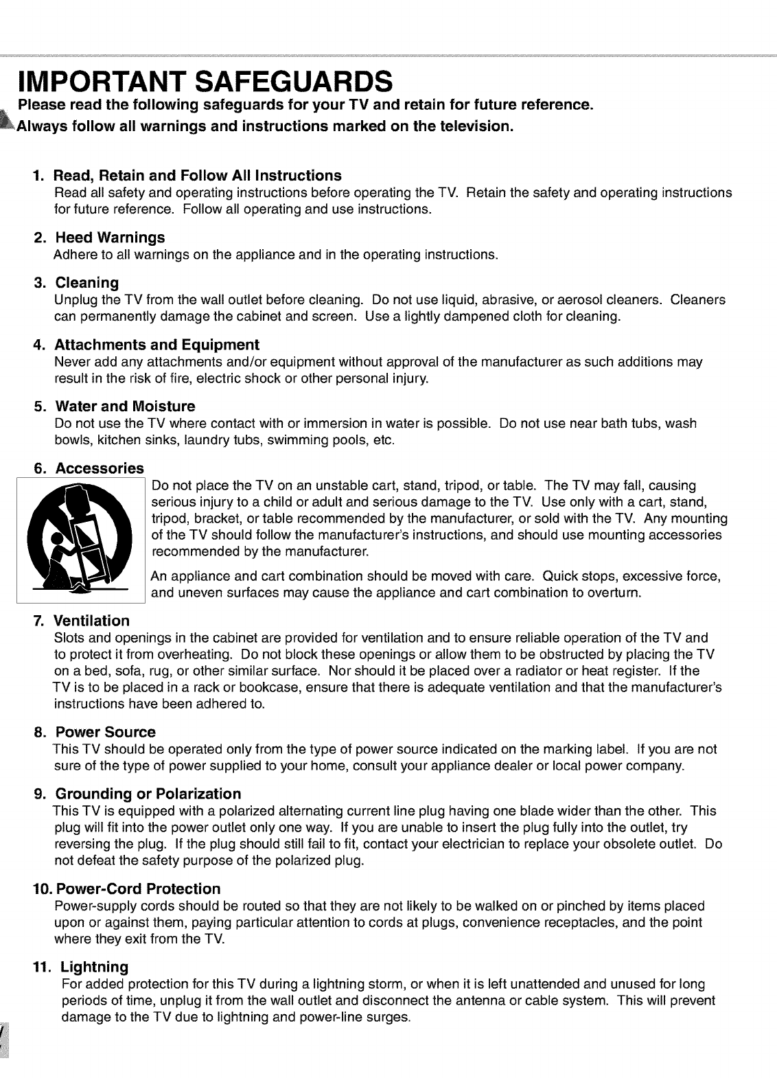
6. Accessories
7.
Do not place the TV on an unstable cart, stand, tripod, or table. The TV may fall, causing
serious injury to a child or adult and serious damage to the TV. Use only with a cart, stand,
tripod, bracket, or table recommended by the manufacturer, or sold with the TV. Any mounting
of the TV should follow the manufacturer's instructions, and should use mounting accessories
recommended by the manufacturer.
An appliance and cart combination should be moved with care. Quick stops, excessive force,
and uneven surfaces may cause the appliance and cart combination to overturn.
Ventilation
Slots and openings in the cabinet are provided for ventilation and to ensure reliable operation of the TV and
to protect it from overheating. Do not block these openings or allow them to be obstructed by placing the TV
on a bed, sofa, rug, or other similar surface. Nor should it be placed over a radiator or heat register. If the
TV is to be placed in a rack or bookcase, ensure that there is adequate ventilation and that the manufacturer's
instructions have been adhered to.
.
g.
Power Source
This TV should be operated only from the type of power source indicated on the marking label. If you are not
sure of the type of power supplied to your home, consult your appliance dealer or local power company.
Grounding or Polarization
This TV is equipped with a polarized alternating current line plug having one blade wider than the other. This
plug will fit into the power outlet only one way. If you are unable to insert the plug fully into the outlet, try
reversing the plug. If the plug should still fail to fit, contact your electrician to replace your obsolete outlet. Do
not defeat the safety purpose of the polarized plug.
10. Power-Cord Protection
Power-supply cords should be routed so that they are not likely to be walked on or pinched by items placed
upon or against them, paying particular attention to cords at plugs, convenience receptacles, and the point
where they exit from the TV.
11. Lightning
For added protection for this TV during a lightning storm, or when it is left unattended and unused for long
periods of time, unplug it from the wall outlet and disconnect the antenna or cable system. This will prevent
damage to the TV due to lightning and power-line surges.
IMPORTANT SAFEGUARDS Continued
12.
13.
14.
15.
16.
17.
18.
19.
20.
Power Lines
An outside antenna system should not be located in the vicinity of overhead power lines or other electric light
or power circuits, or where it can fall into such power lines or circuits. When installing an outside antenna
system, extreme care should be taken to keep from touching such power lines or circuits as contact with
them might be fatal.
Overloading
Do not overload wall outlets and extension cords as this can result in a risk of fire or electric shock.
Object and Liquid Entry
Never push objects of any kind into this TV through openings as they may touch dangerous voltage points or
short-out parts that could result in fire or electric shock. Never spill liquid of any kind on or into the TV.
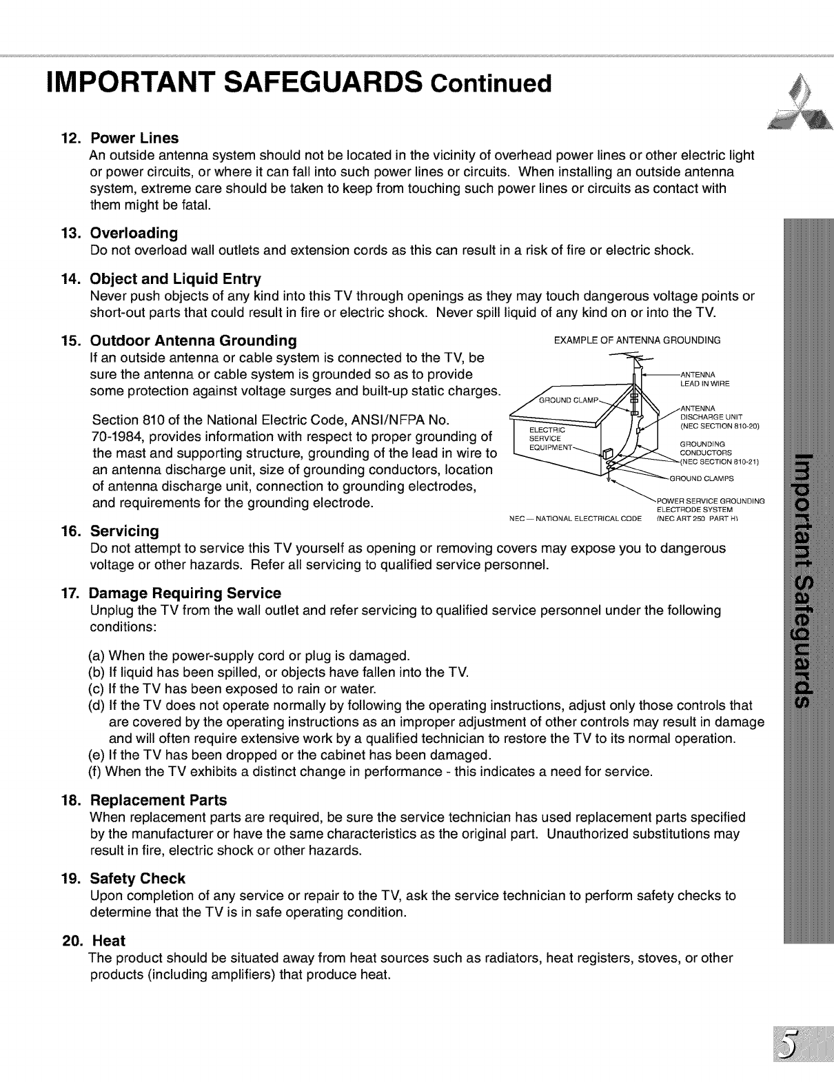
Outdoor Antenna Grounding
If an outside antenna or cable system is connected to the TV, be
sure the antenna or cable system is grounded so as to provide
some protection against voltage surges and built-up static charges.
Section 810 of the National Electric Code, ANSI/NFPA No.
70-1984, provides information with respect to proper grounding of
the mast and supporting structure, grounding of the lead in wire to
an antenna discharge unit, size of grounding conductors, location
of antenna discharge unit, connection to grounding electrodes,
and requirements for the grounding electrode.
Servicing
EXAMPLE OF ANTENNA GROUNDING
ON,T
I EQUIPMENT_I-- / /_ J GROUNDING
_/.,_ CONDUCTORS
"_"_"_" POWER SERVICE GROUNDING
ELECTRODE SYSTEM
NEC - NAT!ONAL ELECTRICAL CODE {NEC ART 250 PART H't
Do not attempt to service this TV yourself as opening or removing covers may expose you to dangerous
voltage or other hazards. Refer all servicing to qualified service personnel.
Damage Requiring Service
Unplug the TV from the wall outlet and refer servicing to qualified service personnel under the following
conditions:
(a) When the power-supply cord or plug is damaged.
(b) If liquid has been spilled, or objects have fallen into the TV.
(c) If the TV has been exposed to rain or water.
(d) If the TV does not operate normally by following the operating instructions, adjust only those controls that
are covered by the operating instructions as an improper adjustment of other controls may result in damage
and will often require extensive work by a qualified technician to restore the TV to its normal operation.
(e) If the TV has been dropped or the cabinet has been damaged.
(f) When the TV exhibits a distinct change in performance - this indicates a need for service.
Replacement Parts
When replacement parts are required, be sure the service technician has used replacement parts specified
by the manufacturer or have the same characteristics as the original part. Unauthorized substitutions may
result in fire, electric shock or other hazards.
Safety Check
Upon completion of any service or repair to the TV, ask the service technician to perform safety checks to
determine that the TV is in safe operating condition.
Heat
The product should be situated away from heat sources such as radiators, heat registers, stoves, or other
products (including amplifiers) that produce heat.

at Mitsubishi Would Like to Thank You
To the Mitsubishi Consumer:
Welcome to the wonderful and exciting world of digital television! We are honored that you
chose Mitsubishi as your premier home entertainment partner. The development team at
Mitsubishi understands that our customers demand and expect the very best. Mitsubishi
is founded on the core beliefs and philosophies that drive us to deliver products that are
both cutting-edge and upgradeable.
While some televisions are destined for near-future obsolescence, Mitsubishi's
HD-upgradeable televisions are engineered with "future-ability." Your television will
continue to provide unparalleled home entertainment for years!
Whether this is your first Mitsubishi consumer electronics product or an addition to your
growing Mitsubishi family, we hope that this television will bring you and your family many
hours of enjoyment.
THE PROMISE
We will engineer and manufacture the upgrades necessary so the HD-Upgradeable
television you purchased today can be made compatible with near-future advances in
digital television and digital interconnectivity. Specifically, we promise that you will be able
to have your television upgraded, at a reasonable cost, to include an off-air HDTV tuner, a
cable TV tuner (for unscrambled programming), an IEEE 1394 (FireWire®) connection, HAVi
system control, and 5C copy protection.
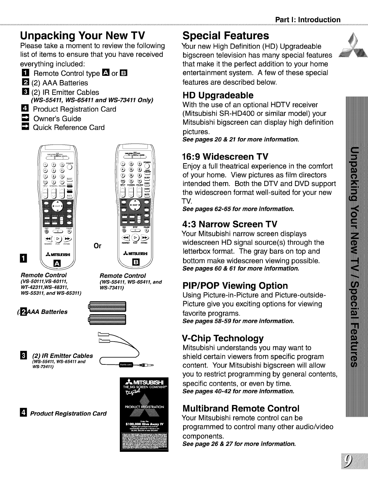
Unpacking Your New TV
Please take a moment to review the following
list of items to ensure that you have received
everything included:
_11 Remote Control type [] or []
[] (2) AAA Batteries
[] (2) IR Emitter Cables
(WS-55411, WS-65411 and WS-73411 Only)
I_1 Product Registration Card
[] Owner's Guide
Quick Reference Card
_MII"SI.IBISI-II
B
Remote Control
(VS-50111,VS-60111,
WT-42311,WS-48311,
WS-55311, and WS-65311)
Or
Remote Control
(WS-55411, WS-65411, and
WS-73411)
(,_4AA Batteries
_1 (2) IR Emitter Cables
(WS-55411, WS-65411 and
WS-73411)
_1 Product Registration Card
Part I: Introduction
Special Features
Your new High Definition (HD) Upgradeable
bigscreen television has many special features
that make it the perfect addition to your home
entertainment system. A few of these special
features are described below.
HD Upgradeable
With the use of an optional HDTV receiver
(Mitsubishi SR-HD400 or similar model) your
Mitsubishi bigscreen can display high definition
pictures.
See pages 20 & 21 for more information.
16:9 Widescreen TV
Enjoy a full theatrical experience in the comfort
of your home. View pictures as film directors
intended them. Both the DTV and DVD support
the widescreen format well-suited for your new
TV.
See pages 62-65 for more information.
4:3 Narrow Screen TV
Your Mitsubishi narrow screen displays
widescreen HD signal source(s) through the
letterbox format. The gray bars on top and
bottom make widescreen viewing possible.
See pages 60 & 61 for more information.
PIP/POP Viewing Option
Using Picture-in-Picture and Picture-outside-
Picture give you exciting options for viewing
favorite programs.
See pages 58-59 for more information.
V-Chip Technology
Mitsubishi understands you may want to
shield certain viewers from specific program
content. Your Mitsubishi bigscreen will allow
you to restrict programming by general contents,
specific contents, or even by time.
See pages 40-42 for more information.
Multibrand Remote Control
Your Mitsubishi remote control can be
programmed to control many other audio/video
components.
See page 26 & 27 for more information.

l
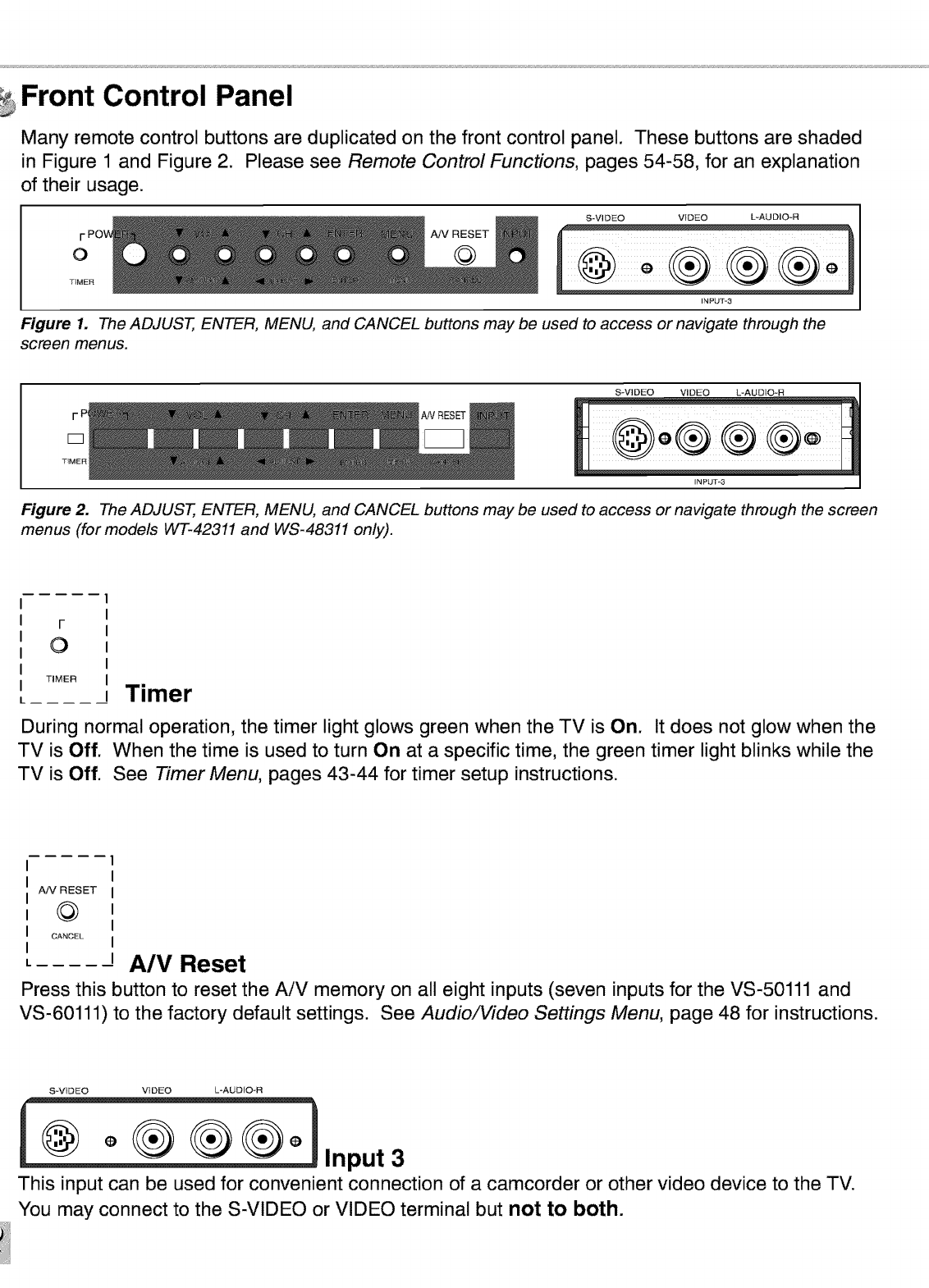
Front Control Panel
Many remote control buttons are duplicated on the front control panel. These buttons are shaded
in Figure 1 and Figure 2. Please see Remote Control Functions, pages 54-58, for an explanation
of their usage.
O
TIMER
S-VIDEO VIDEO L*AUDIO*R
A!V RESET
@
INPUT*3
Figure 1. The ADJUST, ENTER, MENU, and CANCEL buttons may be used to access or navigate through the
screen menus.
S-VIDEO VIDEO L*AUDIO*R
Figure 2. The ADJUST, ENTER, MENU, and CANCEL buttons may be used to access or navigate through the screen
menus (for models WT-42311 and WS-48311 only).
F
0
TIMER Timer
During normal operation, the timer light glows green when the TV is On. It does not glow when the
TV is Off. When the time is used to turn On at a specific time, the green timer light blinks while the
TV is Off. See Timer Menu, pages 43-44 for timer setup instructions.
A!V RESET
@
CANCEL
A/V Reset
Press this button to reset the AiV memory on all eight inputs (seven inputs for the VS-50111 and
VS-60111) to the factory default settings. See Audio/Video Settings Menu, page 48 for instructions.
S-ViDEO VIDEO L-AUDIO*R
_ °_[_ @ __° Input3
This input can be used for convenient connection of a camcorder or other video device to the TV.
You may connect to the S-VIDEO or VIDEO terminal but not to both.
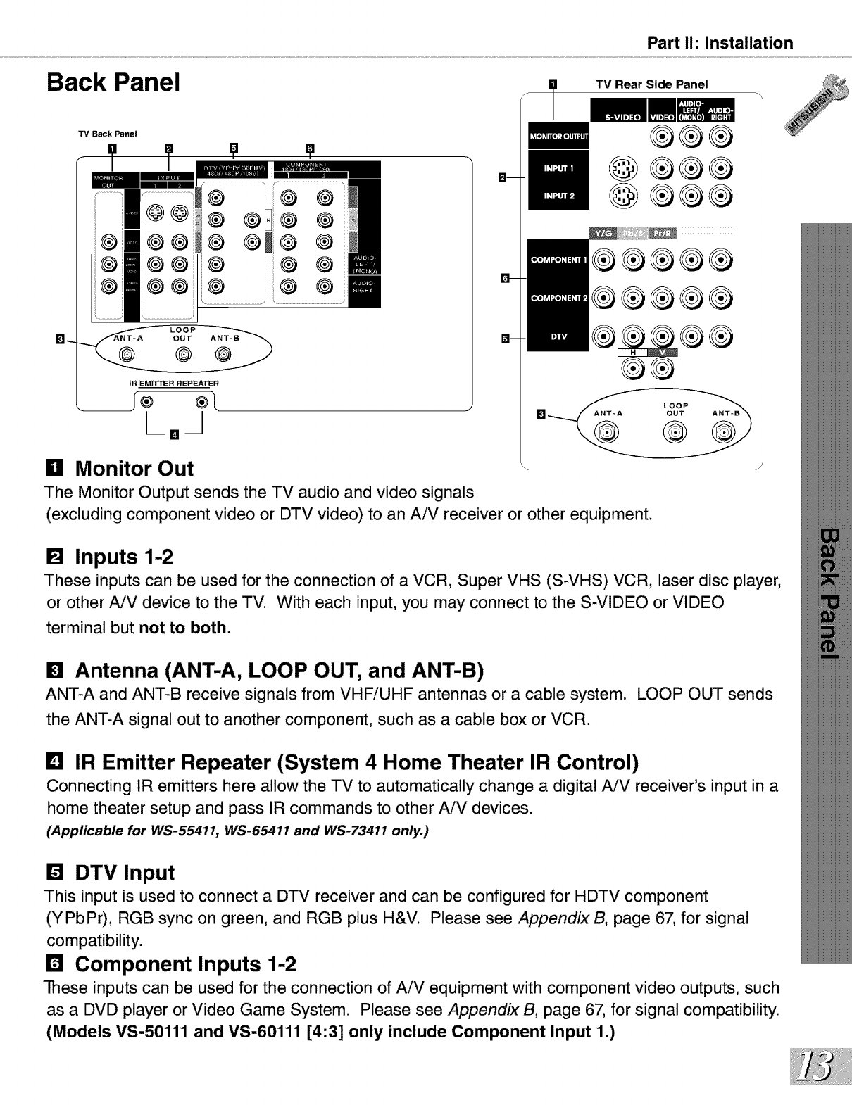
Part I1: Installation
Back Panel
TV Back Panel
I' ?
i® ®
®®D® ®
® ®m® ®
® ® ®
IR EMITTER REPEATER
1°1
n Monitor Out
The Monitor Output sends the TV audio and video signals
TV Rear Side Panel
®®®
@®®®
@®®®
®®®®®
®®®®®
®®®®®
IH_
®®
(excluding component video or DTV video) to an AiV receiver or other equipment.
[] Inputs 1-2
These inputs can be used for the connection of a VCR, Super VHS (S-VHS) VCR, laser disc player,
or other AiV device to the TV. With each input, you may connect to the S-VIDEO or VIDEO
terminal but not to both.
[] Antenna (ANT-A, LOOP OUT, and ANT-B)
ANT-A and ANT-B receive signals from VHFiUHF antennas or a cable system. LOOP OUT sends
the ANT-A signal out to another component, such as a cable box or VCR.
Lq IR Emitter Repeater (System 4 Home Theater IR Control)
Connecting IR emitters here allow the TV to automatically change a digital AiV receiver's input in a
home theater setup and pass IR commands to other AiV devices.
(Applicable for WS-55411, WS-65411 and WS-73411 only.)
[] DTV Input
This input is used to connect a DTV receiver and can be configured for HDTV component
(YPbPr), RGB sync on green, and RGB plus H&V. Please see AppendixB, page 67, for signal
compatibility.
r4 Component Inputs 1-2
-rhese inputs can be used for the connection of AiV equipment with component video outputs, such
as a DVD player or Video Game System. Please see Appendix B, page 67, for signal compatibility.
(Models VS-50111 and VS-60111 [4:3] only include Component Input 1.)
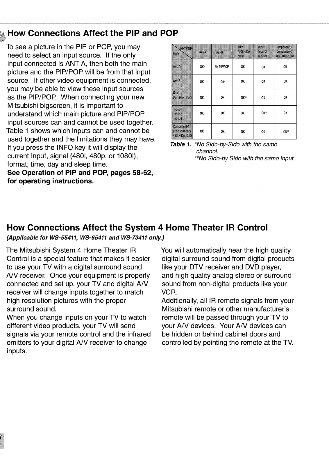
How Connections Affect the PIP and POP
To see a picture in the PIP or POP, you may
need to select an input source. If the only
input connected is ANT-A, then both the main
picture and the PIP/POP will be from that input
source. If other video equipment is connected,
you may be able to view these input sources
as the PIP/POP. When connecting your new
Mitsubishi bigscreen, it is important to
understand which main picture and PIP/POP
input sources can and cannot be used together.
Table 1 shows which inputs can and cannot be
used together and the limitations they may have.
If you press the INFO key it will display the
current Input, signal (480i, 480p, or 10800,
format, time, day and sleep time.
See Operation of PIP and POP, pages 58-62,
for operating instructions.
OK* NoPiP/POP OK OK OK
OK OK* OK OK OK
OK OK OK** OK OK
OK OK OK OK** OK
OK OK OK OK OK**
Table 1. *No Side-by-Side with the same
channel.
**No Side-by Side with the same input.
How Connections Affect the System 4 Home Theater IR Control
(Applicable for WS-55411, WS-65411 and WS-73411 only.)
The Mitsubishi System 4 Home Theater IR
Control is a special feature that makes it easier
to use your TV with a digital surround sound
AiV receiver. Once your equipment is properly
connected and set up, your TV and digital AiV
receiver will change inputs together to match
high resolution pictures with the proper
surround sound.
When you change inputs on your TV to watch
different video products, your TV will send
signals via your remote control and the infrared
emitters to your digital AiV receiver to change
inputs.
You will automatically hear the high quality
digital surround sound from digital products
like your DTV receiver and DVD player,
and high quality analog stereo or surround
sound from non-digital products like your
VCR.
Additionally, all IR remote signals from your
Mitsubishi remote or other manufacturer's
remote will be passed through your TV to
your AiV devices. Your AiV devices can
be hidden or behind cabinet doors and
controlled by pointing the remote at the TV.
Part I1: Installation
Special Setups: A/V Equipment (For System 4 Home Theater IR Control)
VCR: Connect the cables to the TV as directed
on page 17, with one exception. Connect the
audio output connection to the appropriate input
on the back of the AiV receiver (as shown in
Table 1).
•Digital Input Assignment for DVD: Assign
the digital input you used for your DVD player
to the AiV receiver's DVD input selector. This
procedure is explained in your AiV receiver's
Owner's Guide.
DVD: Connect the cables as directed on page
19 (using the COMPONENT-1 input), with one
exception. Connect the digital audio output
connection on the DVD player to the
appropriate digital input on the back of the
digital AiV receiver (as shown in Table 1).
DTV: Connect the cables as directed on pages
20-21, with one exception. Connect the digital
audio output connection on the DTV receiver to
the appropriate digital input on the back of the
digital AiV receiver (as shown in Table 1).
A/V Receiver: Connect as directed on page
18, with two additions. Use an S-Video cable
in step 1 if you have an S-Video VCR. The
TV outputs should be connected to the AiV
receivers input marked TV.
•Auto Standby: ON (See your AiV receiver's
Owner's Guide for this procedure). For all TV
use, the sound will come from the AiV receiver.
Not available with all A/V receivers.
•Digital Assignment for DTV: Assign the
digital input you used for DTV to the AiV
receiver's DTV input selector. This procedure is
explained in your AiV receiver's Owner's Guide.
Infrared Emitter: Connect as shown on page
22.
Special Setups: TV
To correctly setup System 4 use the following
settings
•TV Speakers: OFF
,Audio Output: Fixed
See Audio Video Menu, page 31.
•TV Inputs Appropriately Named
See Input Assignment Menu, page 31.
Remote Control, pages 26-27.
,,Set the slide switch to the TV position and
follow the programming instructions using the
AiV receiver code appropriate for your AiV
receiver, page 27 (Figure 5).
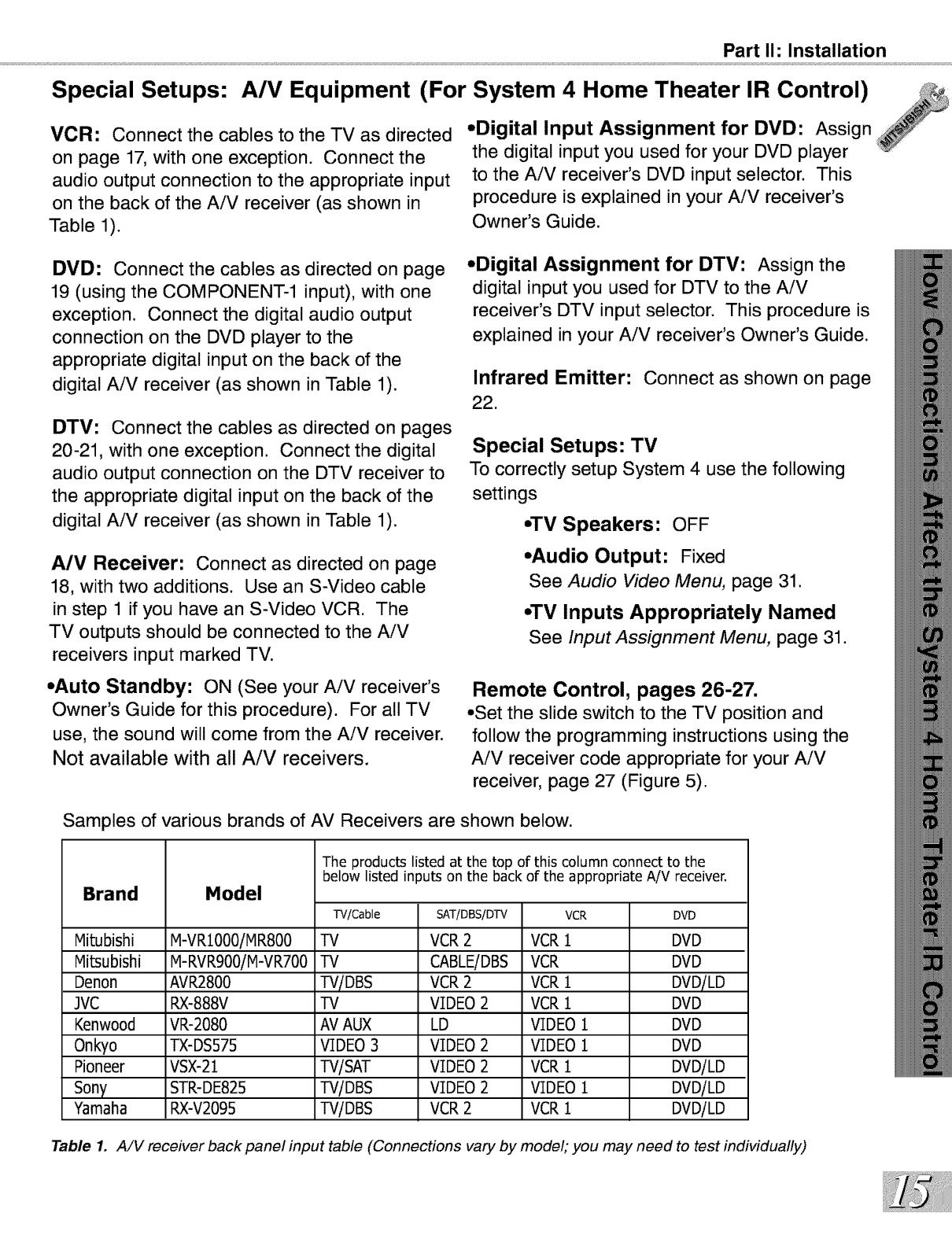
Samples of various brands of AV Receivers are shown below.
Brand Model
The products listed at the top of this column connect to the
below listed inputs on the back of the appropriate AiV receiver.
Mitubishi M-VR1000iMR800
Mitsubishi M-RVR900iM-VRT00
Denon AVR2800
JVC RX-888V
Kenwood VR-2080
Onkyo TX-DS575
Pioneer VSX-21
Sony STR-DE825
Yamaha RX-V2095
"l'V/Cable
TV
TV
TViDBS
TV
AVAUX
VIDEO3
TVlSAT
TViDBS
TViDBS
SAT/DBS/DTV
VCR2
CABLEiDBS
VCR2
VIDEO2
LD
VIDEO2
VIDEO2
VIDEO2
VCR2
VCR
VCR1
VCR
VCR1
VCR1
VIDEO1
VIDEO1
VCR1
VIDEO1
VCR1
DVD
DVD
DVD
DVDiLD
DVD
DVD
DVD
DVDiLD
DVDiLD
DVDiLD
Table 1. A/V receiver back panel input table (Connections vary by model; you may need to test individually)
Connecting an Antenna, Wall Outlet Cable, or Cable Box
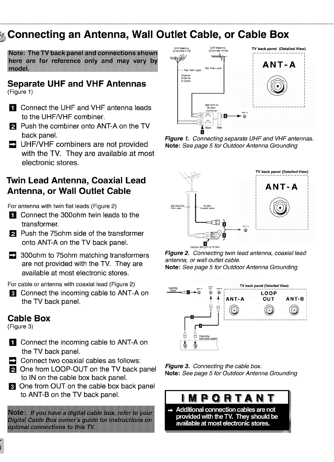
Separate UHF and VHF Antennas
(Figure 1)
_11 Connect the UHF and VHF antenna leads
to the UHFiVHF combiner.
[] Push the combiner onto ANT-A on the TV
back panel.
[] UHF/VHF combiners are not provided
with the TV. They are available at most
electronic stores.
Twin Lead Antenna, Coaxial Lead
Antenna, or Wall Outlet Cable
For antenna with twin flat leads (Figure 2)
_11 Connect the 300ohm twin leads to the
transformer.
[] Push the 75ohm side of the transformer
onto ANT-A on the TV back panel.
300ohm to 75ohm matching transformers
are not provided with the TV. They are
available at most electronic stores.
For cable or antenna with coaxial lead (Figure 2)
[] Connect the incoming cable to ANT-A on
the TV back panel.
Cable Box
(Figure 3)
_11 Connect the incoming cable to ANT-A on
the TV back panel.
Connect two coaxial cables as follows:
[] One from LOOP-OUT on the TV back panel
to IN on the cable box back panel.
[] One from OUT on the cable box back panel
to ANT-B on the TV back panel.
VHF A_tenna
(Chennels 213)
FI_ ]'_4n Leaf
Extem_
Antetltl_
or C_b_e
UHF_te_r_ TV back panel (Detailed View)
(£';h_nnels 14-_9)
I I
ANT-A '
Pl_t r
Figure 1. Connecting separate UHF and VHF antennas.
Note: See page 5 for Outdoor Antenna Grounding
300 Oh#_Fret 75 Ohm
T_r_ Le_d Co_al C_bIe
TV back panel (Detailed View
,,
I
I
I I
Opt!£1tal _ Ohm to 75 Ohm
Figure 2. Connecting twin lead antenna, coaxial lead
antenna, or wall outlet cable.
Note: See page 5 for Outdoor Antenna Grounding
ncoming
Cable ,. .... ;_r ...... TV beck panel (Detailed View)
_lm--_ob ® @ LOOP
IANT'A OUT ANT-B
Figure 3. Connecting the cable box.
Note: See page 5 for Outdoor Antenna Grounding
|MPGRTANT
Part I1: Installation
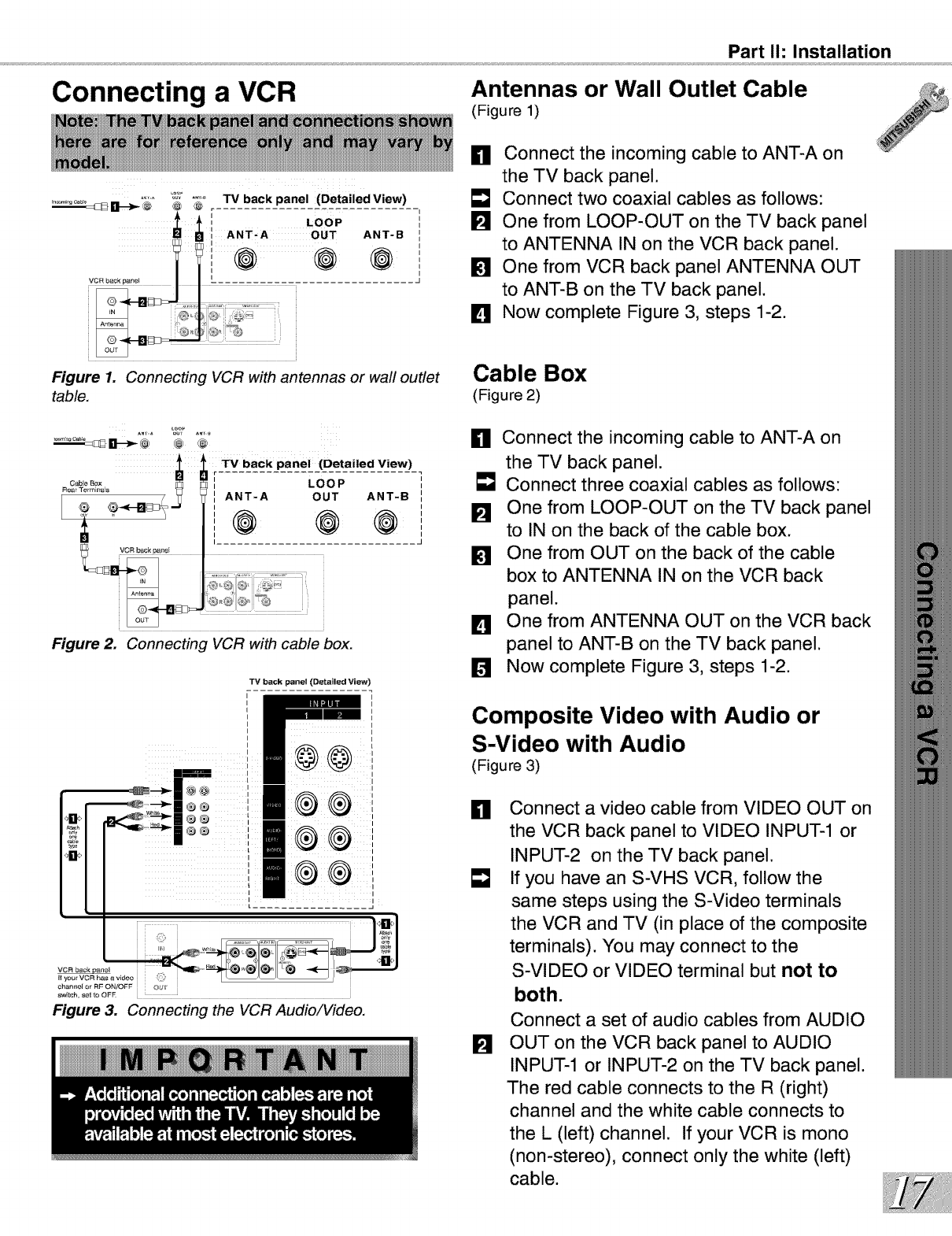
Connecting a VCR Antennas or Wall Outlet Cable
(Figure 1)
Figure 1. Connecting VCR with antennas or wall outlet
table.
Figure 2. Connecting VCR with cable box.
TV back panel (Detailed View)
L................ _
VCR back#_[nel
If your VCR has _ video
chan_lel or RF ON!OFF OUT
switch, se_ to OF_ • • •
Figure 3. Connecting the VCR Audio/Video.
H Connect the incoming cable to ANT-A on
the TV back panel.
E_J Connect two coaxial cables as follows:
One from LOOP-OUT on the TV back panel
to ANTENNA IN on the VCR back panel.
One from VCR back panel ANTENNA OUT
to ANT-B on the TV back panel.
IL_ Now complete Figure 3, steps 1-2.
Cable Box
(Figure 2)
H Connect the incoming cable to ANT-A on
the TV back panel.
E_J Connect three coaxial cables as follows:
One from LOOP-OUT on the TV back panel
to IN on the back of the cable box.
One from OUT on the back of the cable
box to ANTENNA IN on the VCR back
panel.
IL_ One from ANTENNA OUT on the VCR back
panel to ANT-B on the TV back panel.
Now complete Figure 3, steps 1-2.
Composite Video with Audio or
S-Video with Audio
(Figure 3)
H Connect a video cable from VIDEO OUT on
the VCR back panel to VIDEO INPUT-1 or
INPUT-2 on the TV back panel.
If you have an S-VHS VCR, follow the
same steps using the S-Video terminals
the VCR and TV (in place of the composite
terminals). You may connect to the
S-VIDEO or VIDEO terminal but not to
both.
Connect a set of audio cables from AUDIO
OUT on the VCR back panel to AUDIO
INPUT-1 or INPUT-2 on the TV back panel.
The red cable connects to the R (right)
channel and the white cable connects to
the L (left) channel. If your VCR is mono
(non-stereo), connect only the white (left)
cable.
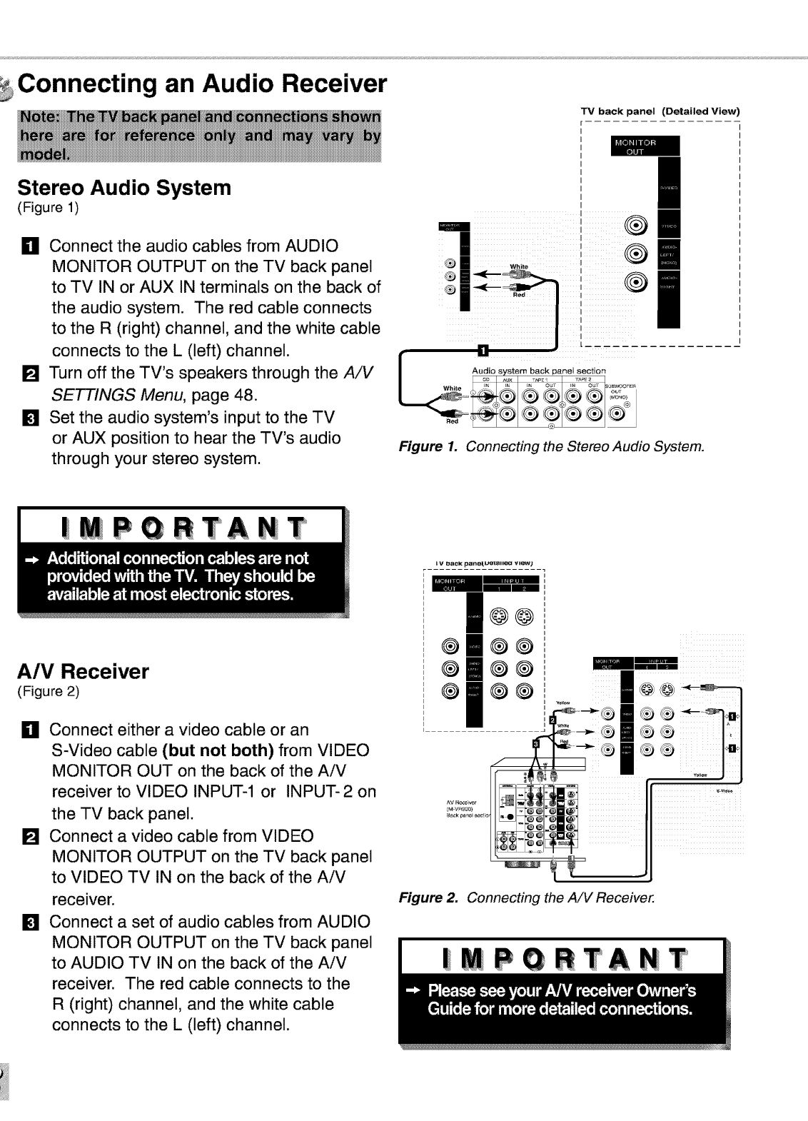
Connecting an Audio Receiver
Stereo Audio System
(Figure 1)
_11 Connect the audio cables from AUDIO
MONITOR OUTPUT on the TV back panel
to TV IN or AUX IN terminals on the back of
the audio system. The red cable connects
to the R (right) channel, and the white cable
connects to the L (left) channel.
[] Turn off the TV's speakers through the AiV
SETTINGS Menu, page 48.
[] Set the audio system's input to the TV
or AUX position to hear the TV's audio
through your stereo system.
TV back panel (Detailed View)
....
Im
m
i
i
'I
I
I
I
I
I
/
C
_ Audio svstem back p_nel section
._ ÷ ® ®
Figure 1. Connecting the Stereo Audio System.
|MPGRTANT
A/V Receiver
(Figure 2)
_11 Connect either a video cable or an
S-Video cable (but not both) from VIDEO
MONITOR OUT on the back of the AiV
receiver to VIDEO INPUT-1 or INPUT-2 on
the TV back panel.
[] Connect a video cable from VIDEO
MONITOR OUTPUT on the TV back panel
to VIDEO TV IN on the back of the AiV
receiver.
[] Connect a set of audio cables from AUDIO
MONITOR OUTPUT on the TV back panel
to AUDIO TV IN on the back of the AiV
receiver. The red cable connects to the
R (right) channel, and the white cable
connects to the L (left) channel.
i t,I I_aCK _llef[U_l I{[_l view}
I@@
omoo
@ ®®
® ®®
Figure 2. Connecting the A/V Receiver.
|MPGRTANIT
WARNING:
Connecting a DVD Player
Part I1: Installation
TV back panel (Detailed View)
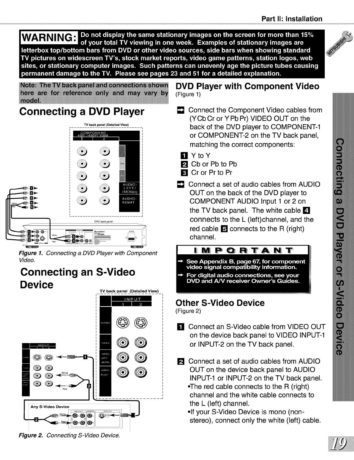
Figure 1. Connecting a DVD Player with Component
Video.
Connecting an S-Video
Device
TV back panel (Detailed View)
DVD Player with Component Video
(Figure 1)
[] Connect the Component Video cables from
(YCb Cr or Y Pb Pr) VIDEO OUT on the
back of the DVD player to COMPONENT-1
or COMPONENT-2 on the TV back panel,
matching the correct components:
Ill YtoY
[] CborPbtoPb
[] CrorPrtoPr
Connect a set of audio cables from AUDIO
OUT on the back of the DVD player to
COMPONENT AUDIO Input 1 or 2 on
the TV back panel. The white cable L_!
connects to the L (left)channel, and the
red cable D connects to the R (right)
channel.
|MPQRTANT
I@@_-_
00
Re_ I
@@
®®
Other S-Video Device
(Figure 2)
il
[]
Connect an S-Video cable from VIDEO OUT
on the device back panel to VIDEO INPUT-1
or INPUT-2 on the TV back panel.
Connect a set of audio cables from AUDIO
OUT on the device back panel to AUDIO
INPUT-1 or INPUT-2 on the TV back panel.
,,The red cable connects to the R (right)
channel and the white cable connects to
the L (left) channel.
,,If your S-Video Device is mono (non-
stereo), connect only the white (left) cable.
Figure 2. Connecting S-Video Device.
g a DTV Recewer
DTV Connectors and Adaptors
(Figure 1)
The TV back panel has five RCA-type
connectors for the DTV connection. The back
panel of your DTV receiver may use RCA-type
connectors or BNC-type connectors. If your
DTV receiver comes with BNC type
connections, you will need to purchase BNC to
RCA adaptors to connect the TV to the DTV
receiver. These adaptors should be available at
most electronic supply stores.
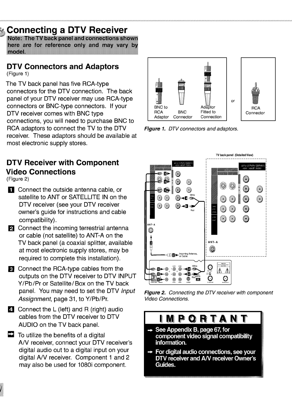
DTV Receiver with Component
Video Connections
(Figure 2)
m
_11 Connect the outside antenna cable, or
satellite to ANT or SATELLITE IN on the
DTV receiver (see your DTV receiver
owner's guide for instructions and cable
compatibility).
[] Connect the incoming terrestrial antenna
or cable (not satellite) to ANT-A on the
TV back panel (a coaxial splitter, available
at most electronic supply stores, may be
required to complete this installation).
[]
D
[]
Connect the RCA-type cables from the
outputs on the DTV receiver to DTV INPUT
YiPbiPr or Satellite/Box on the TV back
panel. You may need to set the DTV Input
Assignment, page 31, to YiPbiPr.
Connect the L (left) and R (right) audio
cables from the DTV receiver to DTV
AUDIO on the TV back panel.
To utilize the benefits of a digital
AiV receiver, connect your DTV receiver's
digital audio out to a digital input on your
digital AiV receiver. Component 1 and 2
may also be used for 1080i component.
BNC to A_
RCA BNC Fitted to
Adaptor Connector Connection
or
Figure 1. DTV connectors and adaptors.
RCA
Connector
@
@
i®®
i!1®®
®@
ANT-A
TV back panel (Detailed View)
@
@@ @
®®l®
®® @
@® @
ANTRA
@
Figure 2. Connecting the DTV receiver with component
Video Connections.
IMPORTANT
Connecting a DTV Receiver
®
®®
ANTRA
_@
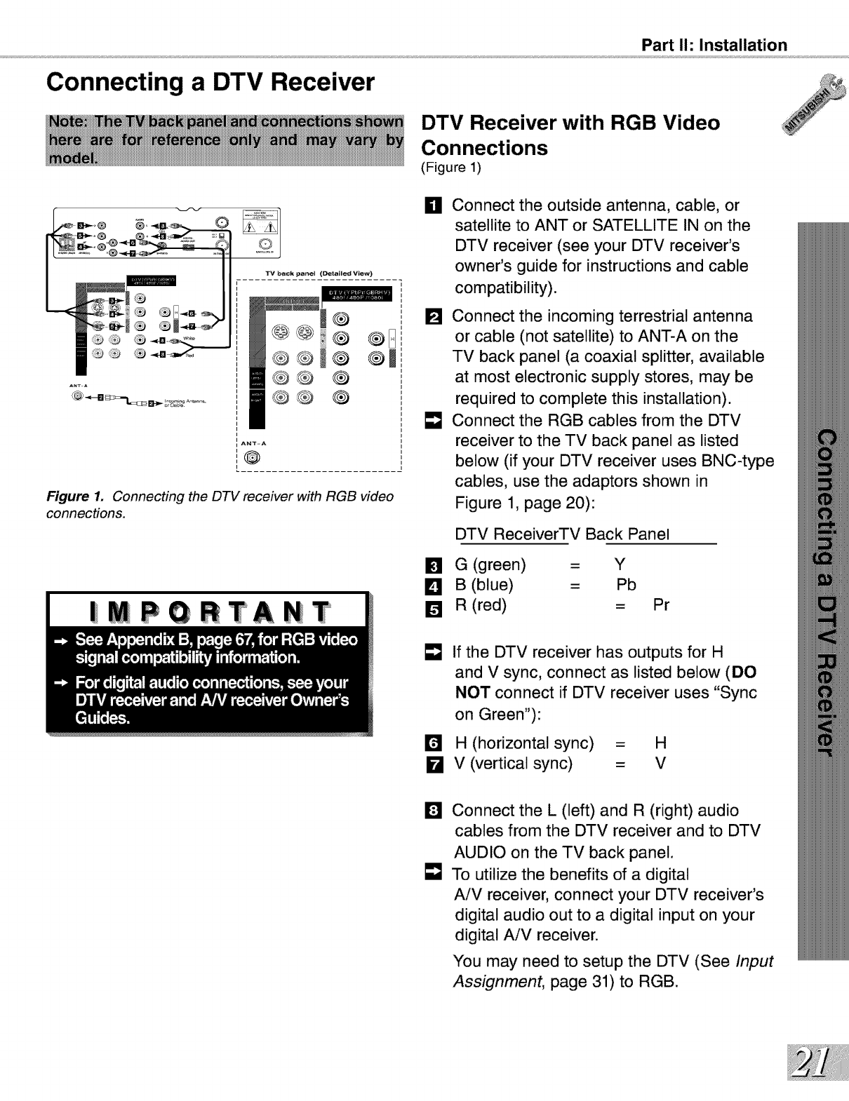
Figure 1. Connecting the DTV receiver with RGB video
connections.
|MPQRTANT
Part I1: Installation
DTV Receiver with RGB Video
Connections
(Figure 1)
HConnect the outside antenna, cable, or
satellite to ANT or SATELLITE IN on the
DTV receiver (see your DTV receiver's
owner's guide for instructions and cable
compatibility).
[] Connect the incoming terrestrial antenna
or cable (not satellite) to ANT-A on the
TV back panel (a coaxial splitter, available
at most electronic supply stores, may be
required to complete this installation).
[] Connect the RGB cables from the DTV
receiver to the TV back panel as listed
below (if your DTV receiver uses BNC-type
cables, use the adaptors shown in
Figure 1, page 20):
DTV ReceiverTV Back Panel
[] G (green) = Y
D B (blue) =Pb
[] R (red) = Pr
=8 If the DTV receiver has outputs for H
and V sync, connect as listed below (DO
NOT connect if DTV receiver uses "Sync
on Green"):
H (horizontal sync) = H
kl V (vertical sync) = V
DConnect the L (left) and R (right) audio
cables from the DTV receiver and to DTV
AUDIO on the TV back panel.
To utilize the benefits of a digital
AiV receiver, connect your DTV receiver's
digital audio out to a digital input on your
digital AiV receiver.
You may need to setup the DTV (See Input
Assignment, page 31) to RGB.
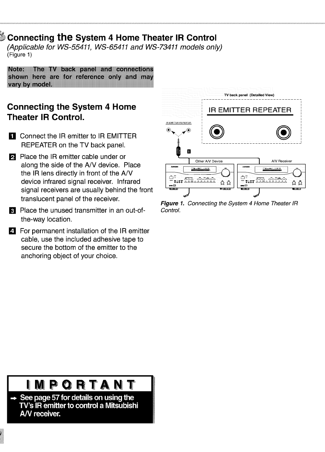
Connecting the System 4 Home Theater IR Control
(Applicable for WS-55411, WS-65411 and WS-73411 models only)
(Figure 1)
Connecting the System 4 Home
Theater IR Control.
_11 Connect the IR emitter to IR EMITTER
REPEATER on the TV back panel. I_ []
[] Place the IR emitter cable under or
along the side of the AiV device. Place
the IR lens directly in front of the AiV
device infrared signal receiver. Infrared
signal receivers are usually behind the front
translucent panel of the receiver.
[] Place the unused transmitter in an out-of-
the-way location.
For permanent installation of the IR emitter
cable, use the included adhesive tape to
secure the bottom of the emitter to the
anchoring object of your choice.
D
IOther AN Device I AN Receiver
,j
Figure 1. Connecting the System 4 Home Theater IR
Control.
Part I1: Installation
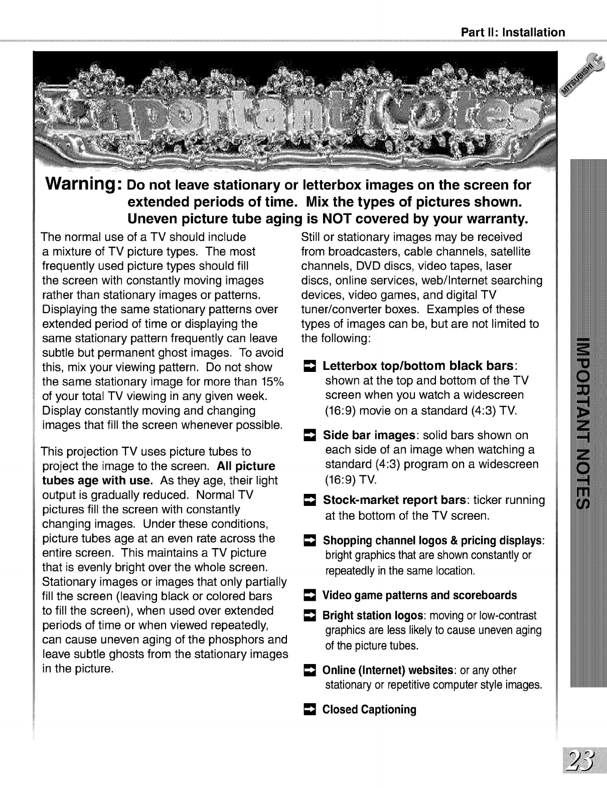
Warning: Do not leave stationary or letterbox images on the screen for
extended periods of time. Mix the types of pictures shown.
Uneven picture tube aging is NOT covered by your warranty.
The normal use of a TV should include
a mixture of TV picture types. The most
frequently used picture types should fill
the screen with constantly moving images
rather than stationary images or patterns.
Displaying the same stationary patterns over
extended period of time or displaying the
same stationary pattern frequently can leave
subtle but permanent ghost images. To avoid
this, mix your viewing pattern. Do not show
the same stationary image for more than 15%
of your total TV viewing in any given week.
Display constantly moving and changing
images that fill the screen whenever possible.
This projection TV uses picture tubes to
project the image to the screen. All picture
tubes age with use. As they age, their light
output is gradually reduced. Normal TV
pictures fill the screen with constantly
changing images. Under these conditions,
picture tubes age at an even rate across the
entire screen. This maintains a TV picture
that is evenly bright over the whole screen.
Stationary images or images that only partially
fill the screen (leaving black or colored bars
to fill the screen), when used over extended
periods of time or when viewed repeatedly,
can cause uneven aging of the phosphors and
leave subtle ghosts from the stationary images
in the picture.
Still or stationary images may be received
from broadcasters, cable channels, satellite
channels, DVD discs, video tapes, laser
discs, online services, webilnternet searching
devices, video games, and digital TV
tuner/converter boxes. Examples of these
types of images can be, but are not limited to
the following:
[] Letterbox top/bottom black bars:
shown at the top and bottom of the TV
screen when you watch a widescreen
(16:9) movie on a standard (4:3) TV.
Side bar images: solid bars shown on
each side of an image when watching a
standard (4:3) program on a widescreen
(16:9) TV.
Stock-market report bars: ticker running
at the bottom of the TV screen.
Shopping channel Iogos & pricing displays:
bright graphics that are shown constantly or
repeatedly in the same location.
Video game patterns and scoreboards
Bright station Iogos: moving or low-contrast
graphics are less likely to cause uneven aging
of the picture tubes.
Online (Internet) websites: or any other
stationary or repetitive computer style images.
Closed Captioning

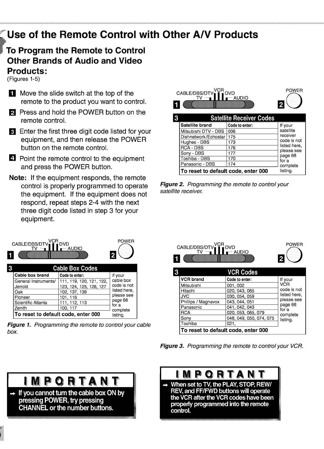
: Use of the Remote Control with Other A/V Products
_To Program the Remote to Control
Other Brands of Audio and Video
Products-
(Figures 1-5)
_11 Move the slide switch at the top of the
remote to the product you want to control.
[] Press and hold the POWER button on the
remote control.
[]
[]
Enter the first three digit code listed for your
equipment, and then release the POWER
button on the remote control.
Point the remote control to the equipment
and press the POWER button.
Note: If the equipment responds, the remote
control is properly programmed to operate
the equipment. If the equipment does not
respond, repeat steps 2-4 with the next
three digit code listed in step 3 for your
equipment.
DTV
POWER
m
Satellite brand Codeto enter: If your
Mitsubishi DTV- DBS 006 satellite
DishnetworkiEchostar 175 receiver
Hughes - DBS 173 code is not
RCA- DBS 176 listed here,
please see
Sony - DBS 177 page 68
Toshiba - DBS 170 for a
Panasonic - DBS 174 complete
TO reset to default code, enter 000 listing.
Figure 2. Programming the remote to control your
satellite receiver.
El TV
POWER
£[_,3FJ_FJ:_I _1_][_
Cable box brand
General Instruments/
Jerrold
Oak
Pioneer
Scientific Atlanta
Zenith
Codetoen_r:
111,119,120,121,122,
123,124,125,126,127
102,137,139
101,116
111,112,113
100,117
To reset to default code, enter 000
If your
cable box
code is not
listed here,
please see
page 68
for a
complete
listing.
Figure 1. Programming the remote to control your cable
box.
D
m
TV
POWER
VCR brand
Mitsubishi
Hitachi
JVC
Phillips /Magnavox
Panasonic
RCA
Sony
Toshiba
C0det0en_r:
001,002
020,043,065
030,054,059
043,044,051
041,042,043
020,053,065,079
048,049,050,074,075
021,
To reset to default code, enter 000
If your
VCR
code is not
listed here,
please see
page 68
for a
complete
listing.
Figure 3. Programming the remote to control your VCR.
iMPORTANT |MPQRTANT
Part II1: Setup
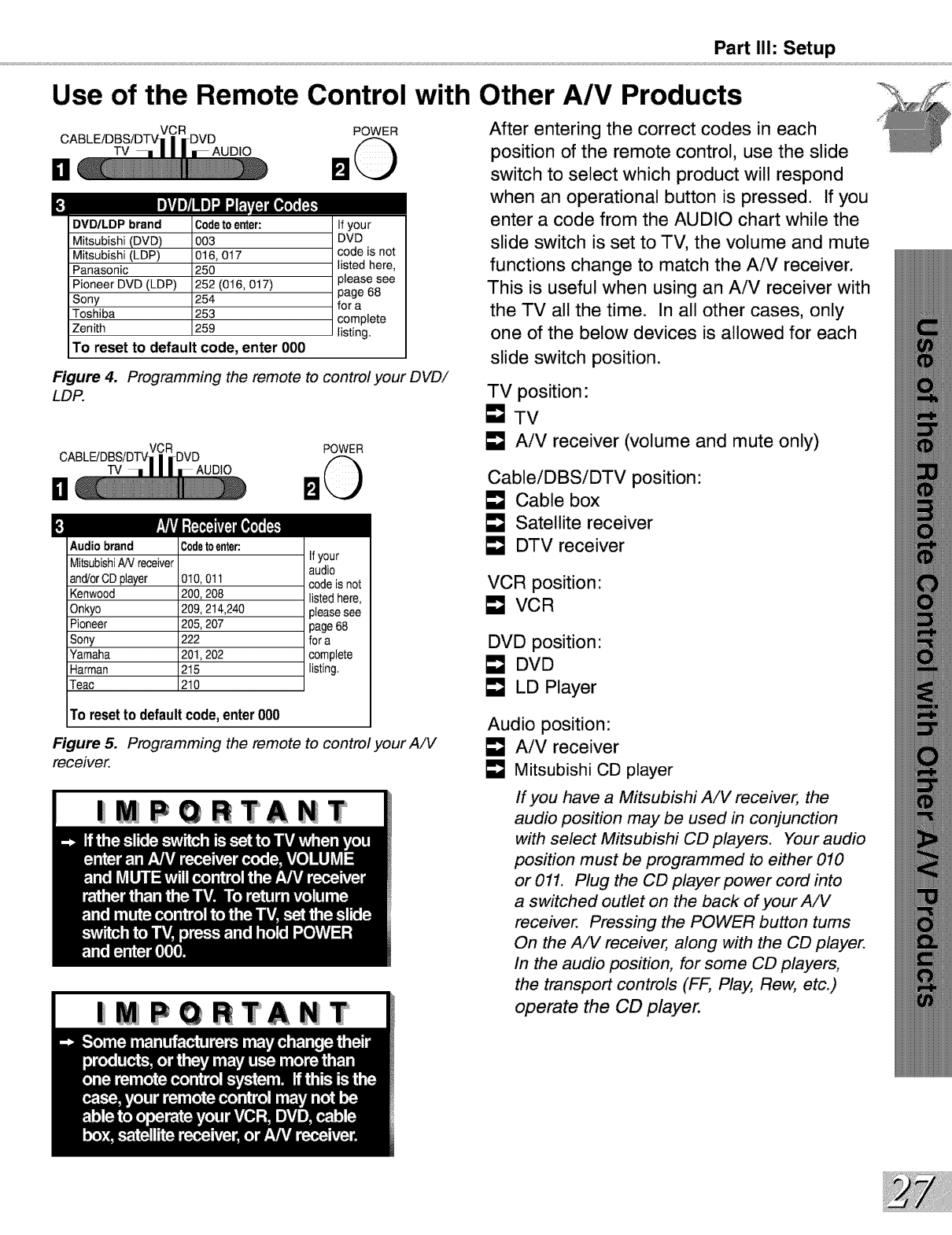
Use of the Remote Control with Other A/V Products
DTV AUDIO
POWER
DVD/LDP brand Codetoenter: if you r
Mitsubishi (DVD) 003 DVD
Mitsubishi (LDP) 016, 017 code is not
Panasonic 250 listed here,
Pioneer DVD (LDP) 252 (016, 017) please see
page 68
Sony 254 for a
Toshiba 253 complete
Zenith 259 listing.
TO reset to default code, enter 000
Figure 4. Programming the remote to control your DVD/
LDP.
TV
il
£
POWER
Audio brand Codetoenter:
MitsubishiAN receiver _ your
audio
and/orCD player 010, 011 code is not
Kenwood 200, 208 listed here,
Onkyo 209, 214,240 please see
Pioneer 205, 207 page 68
Sony 222 for a
Yamaha 201,202 complete
Harman 215 listing
Teac 210
Figure 5.
receiver.
To resetto defaultcode,enter000
Programming the remote to control your A/V
| PQRTANT
|MPQRTANT
After entering the correct codes in each
position of the remote control, use the slide
switch to select which product will respond
when an operational button is pressed. If you
enter a code from the AUDIO chart while the
slide switch is set to TV, the volume and mute
functions change to match the AiV receiver.
This is useful when using an AiV receiver with
the TV all the time. In all other cases, only
one of the below devices is allowed for each
slide switch position.
TV position:
[] TV
AiV receiver (volume and mute only)
CableiDBSiDTV position:
EmJCable box
E_J Satellite receiver
E_J DTV receiver
VCR position"
VCR
DVD position"
E_J DVD
E_J LD Player
Audio position:
AiV receiver
Mitsubishi CD player
If you have a Mitsubishi AiV receiver, the
audio position may be used in conjunction
with select Mitsubishi CD players. Your audio
position must be programmed to either 010
or 011. Plug the CD player power cord into
a switched outlet on the back of your AiV
receiver. Pressing the POWER button turns
On the AiV receiver, along with the CD player.
In the audio position, for some CD players,
the transport controls (FF, Play, Rew, etc.)
operate the CD player.
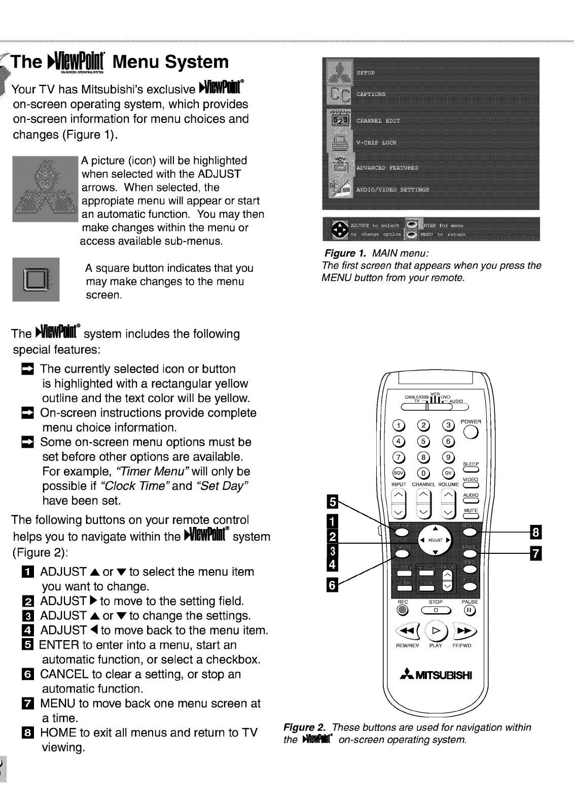
The I !BWPOi Menu System
_Your TV has Mitsubishi's exclusive I_ ®
on-screen operating system, which provides
on-screen information for menu choices and
changes (Figure 1).
A picture (icon) will be highlighted
when selected with the ADJUST
arrows. When selected, the
appropiate menu will appear or start
an automatic function. You may then
make changes within the menu or
access available sub-menus.
A square button indicates that you
may make changes to the menu
screen.
Figure 1. MAIN menu:
The first screen that appears when you press the
MENU button from your remote.
The I_ ®system includes the following
special features:
• qJThe currently selected icon or button
is highlighted with a rectangular yellow
outline and the text color will be yellow.
• qJOn-screen instructions provide complete
menu choice information.
• qJSome on-screen menu options must be
set before other options are available.
For example, "Timer Menu"will only be
possible if "Clock Time"and "Set Day"
have been set.
The following buttons on your remote control
helps you to navigate within the I_MJlI[ ®system
(Figure 2):
_11ADJUST A or v to select the menu item
you want to change.
[] ADJUST I_ to move to the setting field.
[] ADJUST A or v to change the settings.
L_I ADJUST <to move back to the menu item.
[] ENTER to enter into a menu, start an
automatic function, or select a checkbox.
11'41CANCEL to clear a setting, or stop an
automatic function.
kl MENU to move back one menu screen at
a time.
IL_ HOME to exit all menus and return to TV
viewing.
F_EC STOP PAUSE
Q
REWiREV PLAY FF/FWD
,,_ MITSUBISHI
Figure 2. These buttons are used for navigation within
the _B_IE °on-screen operating system.
Part II1: Setup
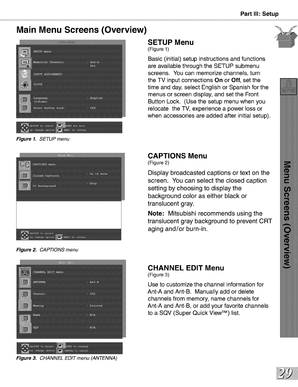
Main Menu Screens (Overview)
Figure 1. SETUP menu
SETUP Menu
(Figure 1)
Basic (initial) setup instructions and functions
are available through the SETUP submenu
screens. You can memorize channels, turn
the TV input connections On or Off, set the
time and day, select English or Spanish for the
menus or screen display, and set the Front
Button Lock. (Use the setup menu when you
relocate the TV, experience a power loss or
when accessories are added after initial setup).
CAPTIONS Menu
(Figure 2)
Display broadcasted captions or text on the
screen. You can select the closed caption
setting by choosing to display the
background color as either black or
translucent gray.
Note: Mitsubishi recommends using the
translucent gray background to prevent CRT
aging and/or burn-in.
Figure 2. CAPTIONS menu
Figure 3. CHANNEL EDIT menu (ANTENNA)
CHANNEL EDIT Menu
(Figure 3)
Use to customize the channel information for
Ant-A and Ant-B. Manually add or delete
channels from memory, name channels for
Ant-A and Ant-B, or add your favorite channels
to a SQV (Super Quick View TM) list.
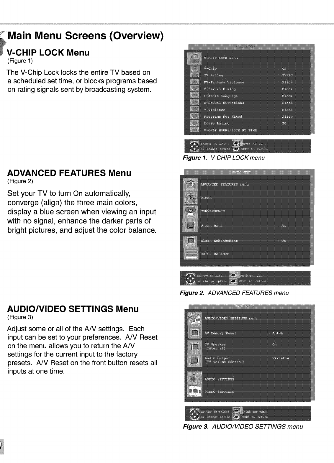
Main Menu Screens (Overview)
V-CHIP LOCK Menu
(Figure 1)
The V-Chip Lock locks the entire TV based on
a scheduled set time, or blocks programs based
on rating signals sent by broadcasting system.
ADVANCED FEATURES Menu
(Figure 2)
Set your TV to turn On automatically,
converge (align) the three main colors,
display a blue screen when viewing an input
with no signal, enhance the darker parts of
bright pictures, and adjust the color balance.
Figure 1. V-CHIP LOCK menu
AUDIO/VIDEO SETTINGS Menu
(Figure 3)
Adjust some or all of the AiV settings. Each
input can be set to your preferences. AiV Reset
on the menu allows you to return the AiV
settings for the current input to the factory
presets. AiV Reset on the front button resets all
inputs at one time.
Figure 2. ADVANCED FEATURES menu
Figure 3. AUDIO!VIDEO SETTINGS menu
SETUP Menu:
Part II1: Setup
Memorize Channels/INPUT ASSIGNMENT
Figure 1. Memorize Channels
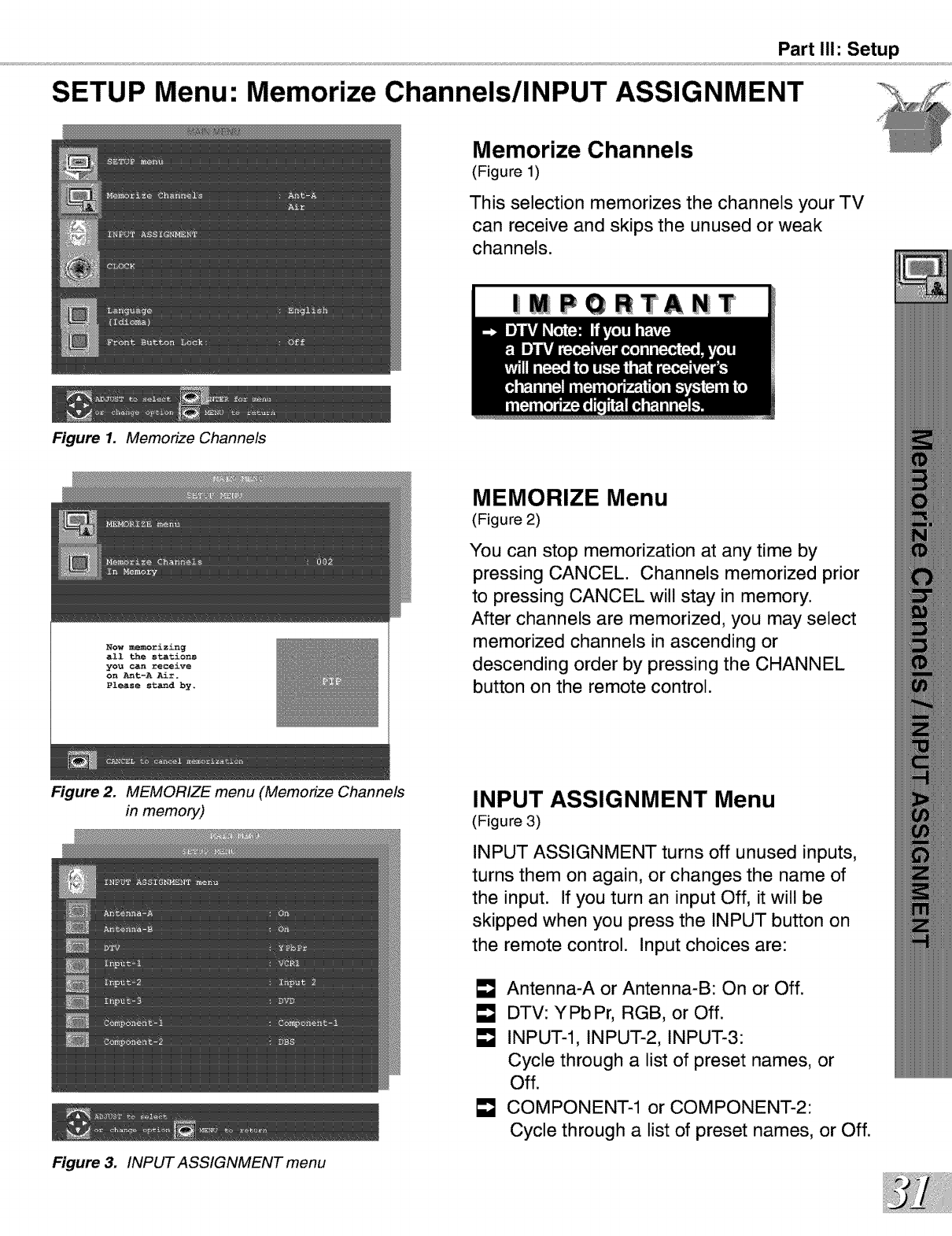
Memorize Channels
(Figure 1)
This selection memorizes the channels your TV
can receive and skips the unused or weak
channels.
|MPQRTANT
Now memorizing
all the stations
you can receive
on Ant-A Air.
Please standby.
MEMORIZE Menu
(Figure 2)
You can stop memorization at any time by
pressing CANCEL. Channels memorized prior
to pressing CANCEL will stay in memory.
After channels are memorized, you may select
memorized channels in ascending or
descending order by pressing the CHANNEL
button on the remote control.
Figure 2. MEMORIZE menu (Memorize Channels
in memory)
Figure 3. INPUT ASSIGNMENT menu
INPUT ASSIGNMENT Menu
(Figure 3)
INPUT ASSIGNMENT turns off unused inputs,
turns them on again, or changes the name of
the input. If you turn an input Off, it will be
skipped when you press the INPUT button on
the remote control. Input choices are:
[] Antenna-A or Antenna-B: On or Off.
LmJDTV: YPbPr, RGB, or Off.
INPUT-l, INPUT-2, INPUT-3:
Cycle through a list of preset names, or
Off.
COMPONENT-1 or COMPONENT-2:
Cycle through a list of preset names, or Off.
SETUP Menu:
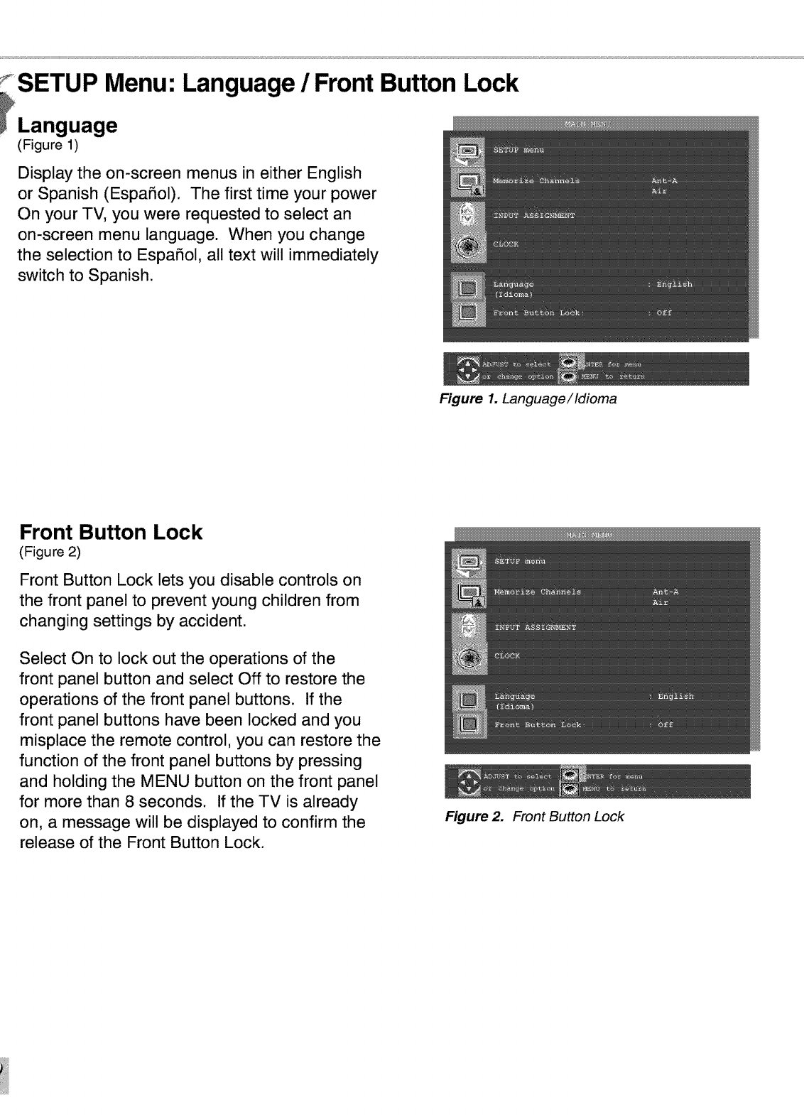
_Language
(Figure 1)
Language /Front Button Lock
Display the on-screen menus in either English
or Spanish (EspaSol). The first time your power
On your TV, you were requested to select an
on-screen menu language. When you change
the selection to EspaSol, all text will immediately
switch to Spanish.
Figure 1. Language/Idioma
Front Button Lock
(Figure 2)
Front Button Lock lets you disable controls on
the front panel to prevent young children from
changing settings by accident.
Select On to lock out the operations of the
front panel button and select Off to restore the
operations of the front panel buttons. If the
front panel buttons have been locked and you
misplace the remote control, you can restore the
function of the front panel buttons by pressing
and holding the MENU button on the front panel
for more than 8 seconds. If the TV is already
on, a message will be displayed to confirm the
release of the Front Button Lock.
Figure 2. Front Button Lock
CLOCK Menu: Clock Setting /Tme Zone /D.S.T.
Figure 1. Clock Setting (Auto)
Figure 2. Time Zone
Figure 3. Daylight Savings Time
Part II1: Setup
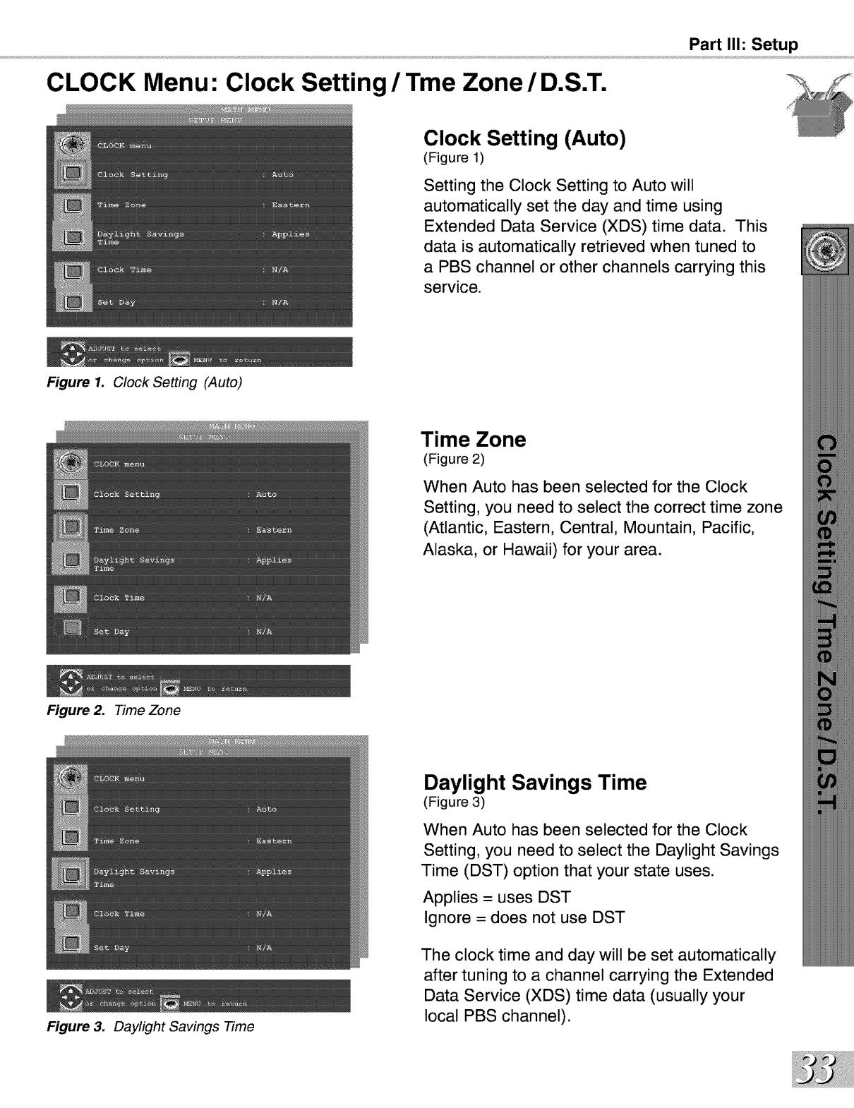
Clock Setting (Auto)
(Figure 1)
Setting the Clock Setting to Auto will
automatically set the day and time using
Extended Data Service (XDS) time data. This
data is automatically retrieved when tuned to
a PBS channel or other channels carrying this
service.
Time Zone
(Figure 2)
When Auto has been selected for the Clock
Setting, you need to select the correct time zone
(Atlantic, Eastern, Central, Mountain, Pacific,
Alaska, or Hawaii) for your area.
Daylight Savings Time
(Figure 3)
When Auto has been selected for the Clock
Setting, you need to select the Daylight Savings
Time (DST) option that your state uses.
Applies = uses DST
Ignore = does not use DST
The clock time and day will be set automatically
after tuning to a channel carrying the Extended
Data Service (XDS) time data (usually your
local PBS channel).
Clock Menu:
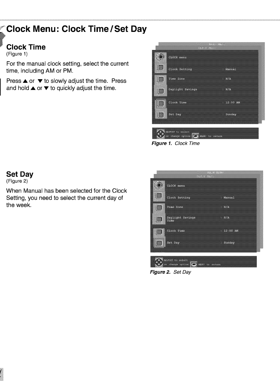
Clock Time
(Figure 1)
Clock Time /Set
For the manual clock setting, select the current
time, including AM or PM.
Press Aor •to slowly adjust the time. Press
and hold Aor • to quickly adjust the time.
Day
Figure 1. Clock Time
Set Day
(Figure 2)
When Manual has been selected for the Clock
Setting, you need to select the current day of
the week.
Figure 2. Set Day
Part II1: Setup
CAPTIONS Menu: Closed Captions
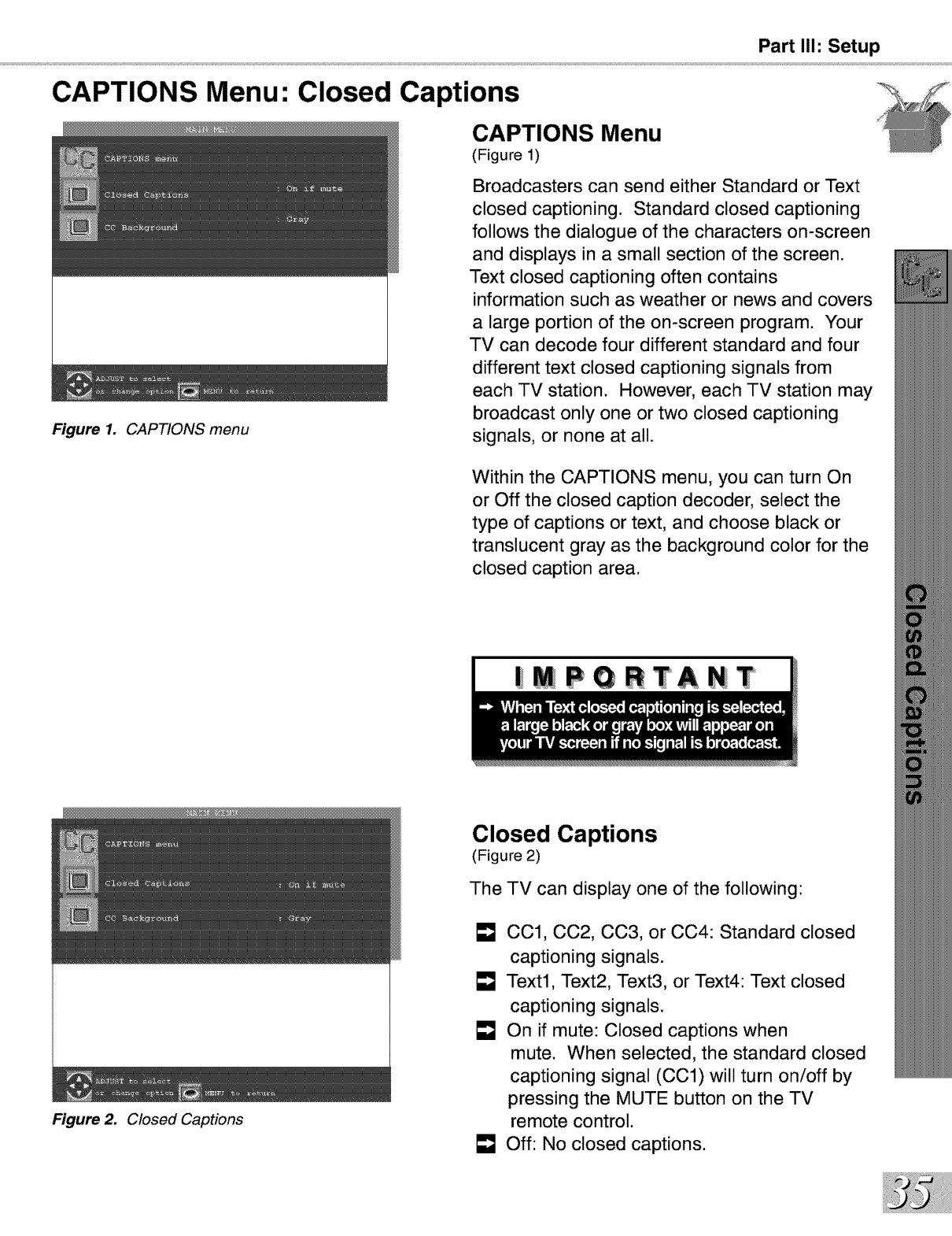
CAPTIONS Menu
(Figure 1)
Figure 1. CAPTIONS menu
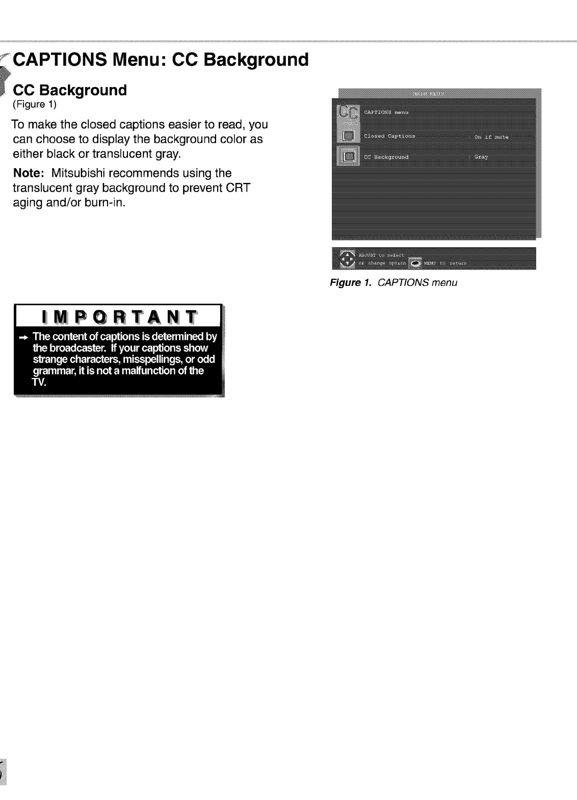
Figure 2. Closed Captions
Broadcasters can send either Standard or Text
closed captioning. Standard closed captioning
follows the dialogue of the characters on-screen
and displays in a small section of the screen.
Text closed captioning often contains
information such as weather or news and covers
a large portion of the on-screen program. Your
TV can decode four different standard and four
different text closed captioning signals from
each TV station. However, each TV station may
broadcast only one or two closed captioning
signals, or none at all.
Within the CAPTIONS menu, you can turn On
or Off the closed caption decoder, select the
type of captions or text, and choose black or
translucent gray as the background color for the
closed caption area.
| PGRTANT
Closed Captions
(Figure 2)
The TV can display one of the following:
LmJCC1, CC2, CC3, or CC4: Standard closed
captioning signals.
[] Text1, Text2, Text3, or Text4: Text closed
captioning signals.
On if mute: Closed captions when
mute. When selected, the standard closed
captioning signal (CC1) will turn on/off by
pressing the MUTE button on the TV
remote control.
Off: No closed captions.
f_CAPTIONS Menu:
_CC Background
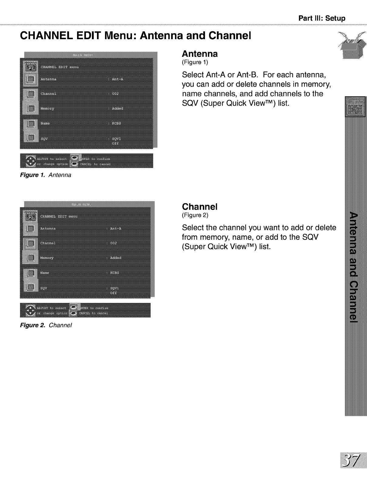
(Figure 1)
CO Background
To make the closed captions easier to read, you
can choose to display the background color as
either black or translucent gray.
Note: Mitsubishi recommends using the
translucent gray background to prevent CRT
aging and/or burn-in.
Figure 1. CAPTIONS menu
|MPGRTANT
CHANNEL EDIT Menu: Antenna and Channel
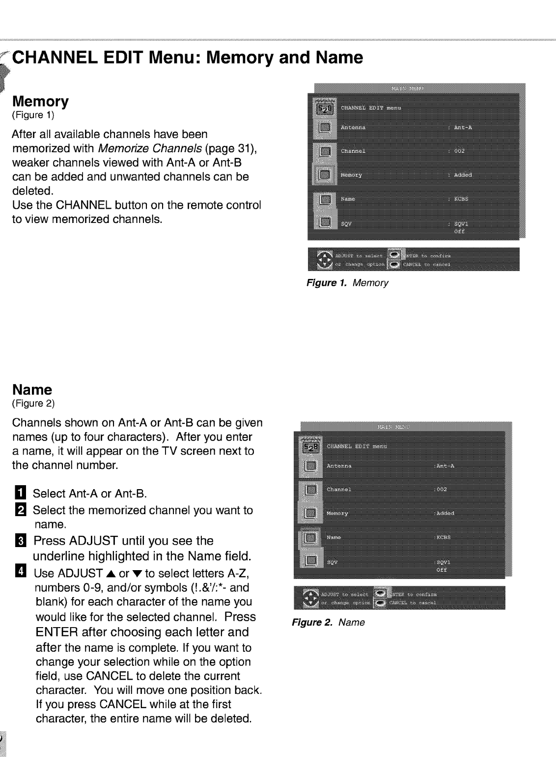
Figure 1. Antenna
Figure 2. Channel
Part II1: Setup
Antenna
(Figure 1)
Select Ant-A or Ant-B. For each antenna,
you can add or delete channels in memory,
name channels, and add channels to the
SQV (Super Quick View TM) list.
Channel
(Figure 2)
Select the channel you want to add or delete
from memory, name, or add to the SQV
(Super Quick View TM) list.
CHANNEL EDIT Menu: Memory and Name
Memory
(Figure 1)
After all available channels have been
memorized with Memorize Channels (page 31),
weaker channels viewed with Ant-A or Ant-B
can be added and unwanted channels can be
deleted.
Use the CHANNEL button on the remote control
to view memorized channels.
Figure 1. Memory
Name
(Figure 2)
Channels shown on Ant-A or Ant-B can be given
names (up to four characters). After you enter
a name, it will appear on the TV screen next to
the channel number.
0
m
D
Select Ant-A or Ant-B.
Select the memorized channel you want to
name.
Press ADJUST until you see the
underline highlighted in the Name field.
Use ADJUST • or v to select letters A-Z,
numbers 0-9, and/or symbols (!.&'i:*- and
blank) for each character of the name you
would like for the selected channel. Press
ENTER after choosing each letter and
after the name is complete. If you want to
change your selection while on the option
field, use CANCEL to delete the current
character. You will move one position back.
If you press CANCEL while at the first
character, the entire name will be deleted.
Figure 2. Name
CHANNEL EDIT Menu: SQV (Super Quick View TM)
Part II1: Setup
SQV (Super Quick View TM)
Using The Remote Control
Changing SQV banks using the remote
control:
0
[]
Press the SQV button.
To change memory banks, press a number
button within 5 seconds of pressing the
SQV button.
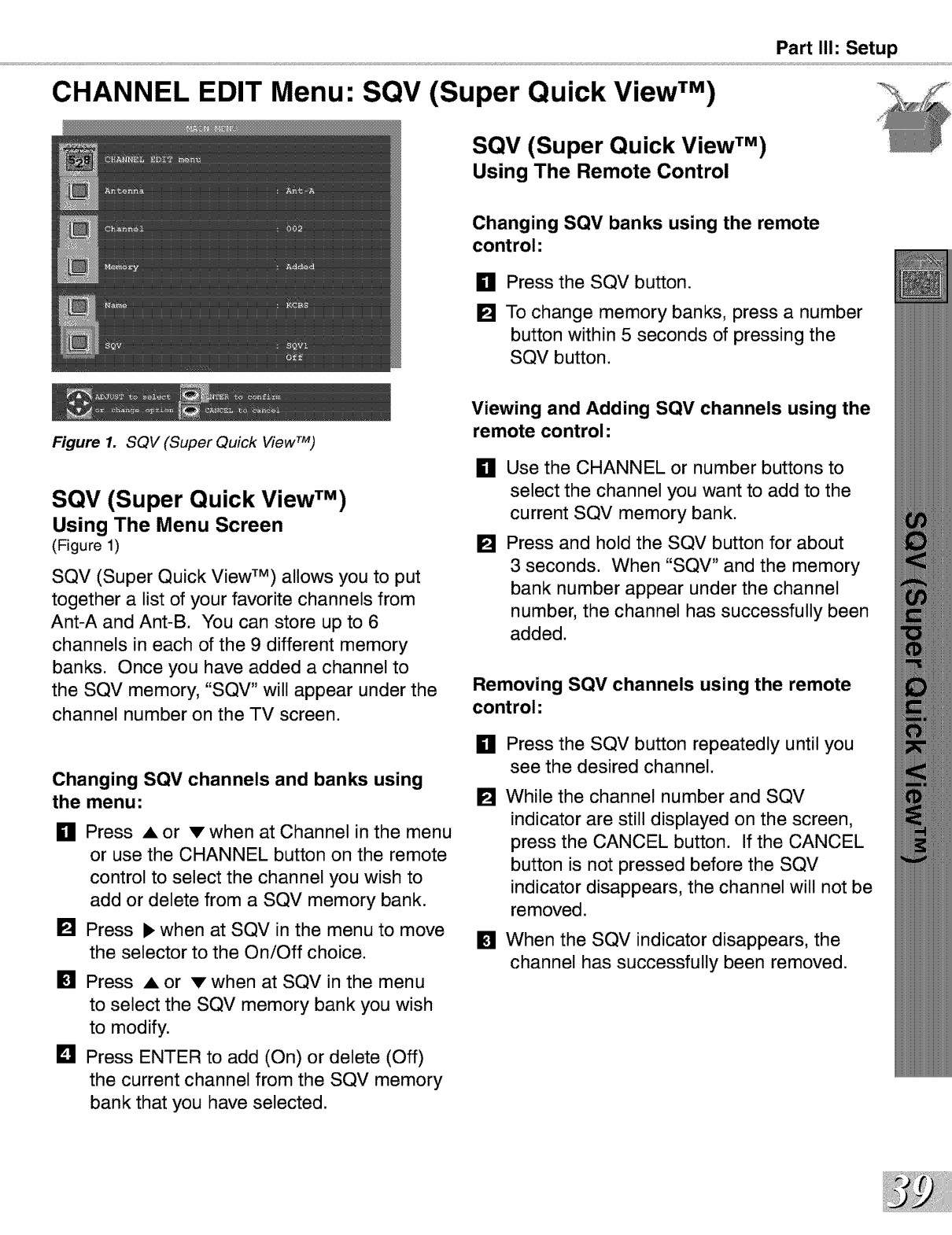
Figure 1. SQV (Super Quick View TM)
SQV (Super Quick View TM)
Using The Menu Screen
(Figure 1)
SQV (Super Quick View TM) allows you to put
together a list of your favorite channels from
Ant-A and Ant-B. You can store up to 6
channels in each of the 9 different memory
banks. Once you have added a channel to
the SQV memory, "SQV" will appear under the
channel number on the TV screen.
Changing SQV channels and banks using
the menu:
gPress =, or v when at Channel in the menu
or use the CHANNEL button on the remote
control to select the channel you wish to
add or delete from a SQV memory bank.
[] Press • when at SQV in the menu to move
the selector to the On/Off choice.
[]
D
Press • or v when at SQV in the menu
to select the SQV memory bank you wish
to modify.
Press ENTER to add (On) or delete (Off)
the current channel from the SQV memory
bank that you have selected.
Viewing and Adding SQV channels using the
remote control:
H
[]
Use the CHANNEL or number buttons to
select the channel you want to add to the
current SQV memory bank.
Press and hold the SQV button for about
3 seconds. When "SQV" and the memory
bank number appear under the channel
number, the channel has successfully been
added.
Removing SQV channels using the remote
control:
_11 Press the SQV button repeatedly until you
see the desired channel.
[]
[]
While the channel number and SQV
indicator are still displayed on the screen,
press the CANCEL button. If the CANCEL
button is not pressed before the SQV
indicator disappears, the channel will not be
removed.
When the SQV indicator disappears, the
channel has successfully been removed.
V-CHIP Menu: V-CHIP LOCK
_Entry to the V-CHIP LOCK
(Figures 1-2)
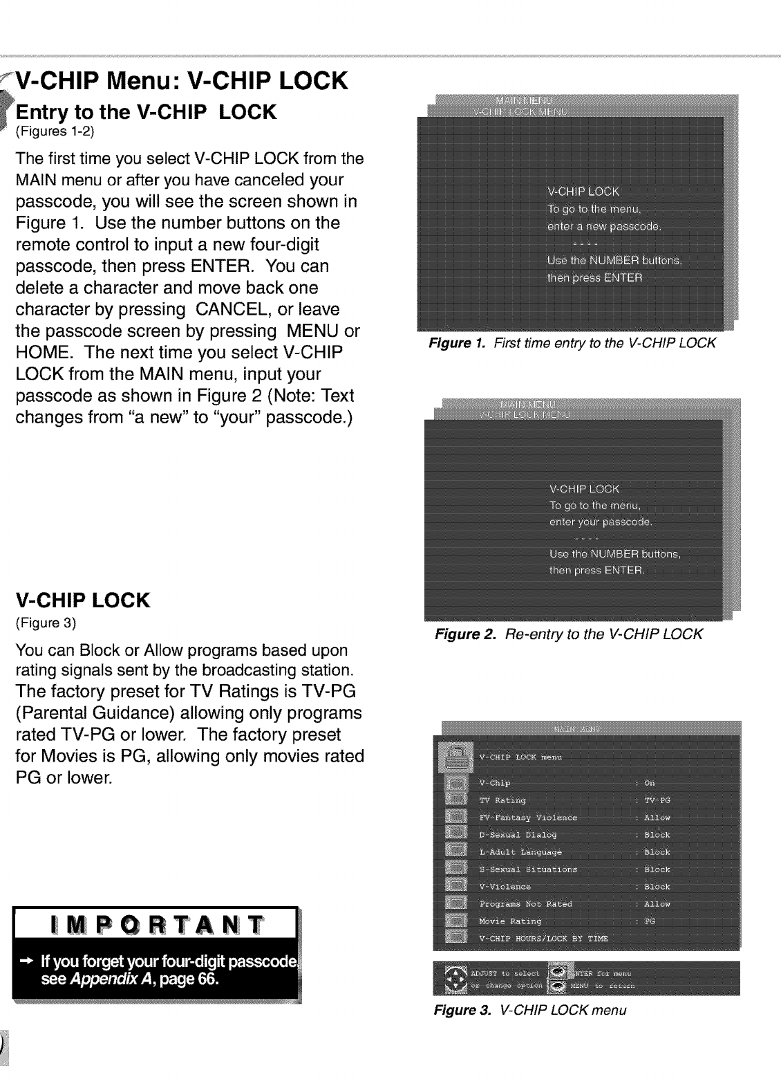
The first time you select V-CHIP LOCK from the
MAIN menu or after you have canceled your
passcode, you will see the screen shown in
Figure 1. Use the number buttons on the
remote control to input a new four-digit
passcode, then press ENTER. You can
delete a character and move back one
character by pressing CANCEL, or leave
the passcode screen by pressing MENU or
HOME. The next time you select V-CHIP
LOCK from the MAIN menu, input your
passcode as shown in Figure 2 (Note: Text
changes from "a new" to "your" passcode.)
V-CHIP LOCK
(Figure 3)
You can Block or Allow programs based upon
rating signals sent by the broadcasting station.
The factory preset for TV Ratings is TV-PG
(Parental Guidance) allowing only programs
rated TV-PG or lower. The factory preset
for Movies is PG, allowing only movies rated
PG or lower.
|MPORTANiT
Figure 1. First time entry to the V-CHIP LOCK
Figure 2. Re-entry to the V-CHIP LOCK
Figure 3. V-CHIP LOCK menu
Part II1: Setup
V-CHIP LOCK Menu: V-Chip (continuation)
V-Chip Signal Information
When provided by the broadcaster, V-Chip ratings can be used to control which programs can be viewed or will be
blocked. When V-Chip ratings are sent, you will see the ratings when you change the channel or when you press
the INFO button on the remote control. The V-Chip rating includes both TV and Movie ratings. TV ratings apply to
programs and movies developed for TV. TV ratings can have supplemental blocking by content categories. Movie
ratings use MPAA ratings for movies released in theaters.
TV Ratings:
Used with TV programs and made for TV movies.
TV-Y Youth, designed for children under the age of 7.
TV-Y7 Youth, 7 years old and older. Designed for children 7 years old and older.
TV-G General Audience. Designed for the entire family to view.
TV-PG Parental Guidence. Parental Guidence is recommended, may not be suitable for some children.
TV-14 Adolescent 14 years old and older. Not recommended for children under the age of 14.
TV-MA Mature Audience. Recommend for adults only.
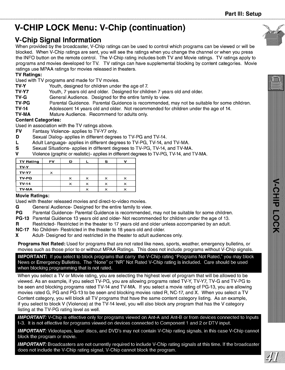
Content Categories:
Used in association with the TV ratings above.
FV Fantasy Violence- applies to TV-Y7 only.
DSexual Dialog- applies in different degrees to TV-PG and TV-14.
L Adult Language- applies in different degrees to TV-PG, TV-14, and TV-MA.
SSexual Situations- applies in different degrees to TV-PG, TV-14, and TV-MA.
V Violence (graphic or realistic)- applies in different degrees to TV-PG, TV-14, and TV-MA.
TV Rating FV D L S V
TV-Y
TM-Y7 x
TM-PG x x x x
TM-14 x x x x
TM-MA xxx
Movie Ratings:
Used with theater released movies and direct-to-video movies.
G
PG
PG-13
R
N0-17
X
General Audience- Designed for the entire family to view.
Parental Guidence- Parental Guidence is recommended, may not be suitable for some children.
Parental Guidence 13 years old and older- Not recommended for children under the age of 13.
Restricted- Restricted in the theater to 17 years old and older unless accompanied by an adult.
No Children- Restricted in the theater to 18 years old and older.
Adult- Designed for and restricted in the theater to adult audiences only.
Programs Not Rated: Used for programs that are not rated like news, sports, weather, emergency bulletins, or
movies such as those prior to or without MPAA Ratings. This does not include programs without V-Chip signals.
When you select a TV or Movie rating, you are selecting the highest level of program that will be allowed to be
viewed. As an example, if you select TV-PG, you are allowing programs rated TV-Y, TV-Y7, TV-G and TV-PG to
be seen and blocking programs rated TV-14 and TV-MA. If you select a movie rating of PC-13, you are allowing
movies rated G, PG and PC-13 to be seen and blocking movies rated R, NC-17, and X. When you select a TV
Content category, you will block all TV programs that have the same content category listing. As an example,
if you select to block V (Violence) at the TV-14 level, you will also block any program that has the V category
listing at the TV-PG rating level as well.
V-CHIP LOCK Menu: V-Chip Hours/Lock by Time
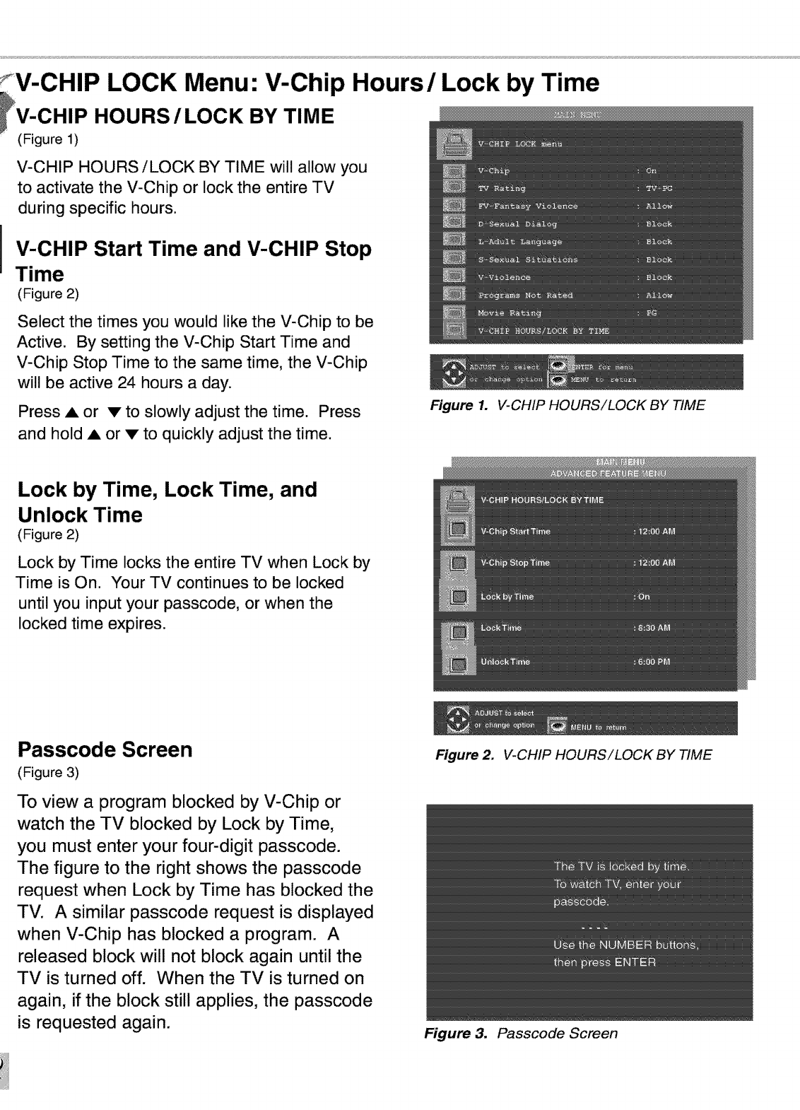
_V-CHIP HOURS /LOCK BY TIME
(Figure 1)
V-CHIP HOURS/LOCK BY TIME will allow you
to activate the V-Chip or lock the entire TV
during specific hours.
V-CHIP Start Time and V-CHIP Stop
Time
(Figure 2)
Select the times you would like the V-Chip to be
Active. By setting the V-Chip Start Time and
V-Chip Stop Time to the same time, the V-Chip
will be active 24 hours a day.
Press A or • to slowly adjust the time. Press
and hold A or • to quickly adjust the time.
Lock by Time, Lock Time, and
Unlock Time
(Figure 2)
Lock by Time locks the entire TV when Lock by
Time is On. Your TV continues to be locked
until you input your passcode, or when the
locked time expires.
Passcode Screen
(Figure 3)
To view a program blocked by V-Chip or
watch the TV blocked by Lock by Time,
you must enter your four-digit passcode.
The figure to the right shows the passcode
request when Lock by Time has blocked the
TV. A similar passcode request is displayed
when V-Chip has blocked a program. A
released block will not block again until the
TV is turned off. When the TV is turned on
again, if the block still applies, the passcode
is requested again.
Figure 1. V-CHIP HOURS/LOCK BY TIME
Figure 2. V-CHIP HOURS/LOCK BY TIME
Figure 3. Passcode Screen
Part II1: Setup
ADVANCED FEATURES Menu: TIMER, Timer Menu, and Set Time
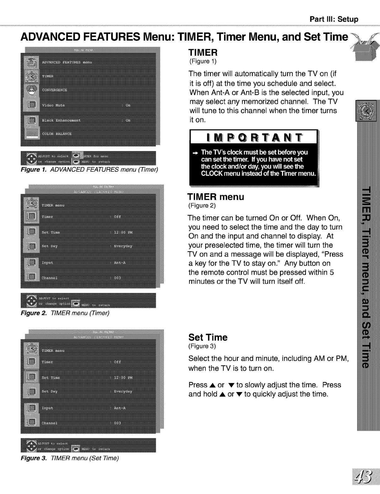
TIMER
(Figure 1)
The timer will automatically turn the TV on (if
it is off) at the time you schedule and select.
When Ant-A or Ant-B is the selected input, you
may select any memorized channel. The TV
will tune to this channel when the timer turns
it on.
|MPGRTANT
Figure 1. ADVANCED FEATURES menu (Timer)
Figure 2. TIMER menu (Timer)
Figure 3. TIMER menu (Set Time)
TIMER menu
(Figure 2)
The timer can be turned On or Off. When On,
you need to select the time and the day to turn
On and the input and channel to display. At
your preselected time, the timer will turn the
TV on and a message will be displayed, "Press
a key for the TV to stay on." Any button on
the remote control must be pressed within 5
minutes or the TV will turn itself off.
Set Time
(Figure 3)
Select the hour and minute, including AM or PM,
when the TV is to turn on.
Press • or v to slowly adjust the time. Press
and hold • or v to quickly adjust the time.
ADVANCED FEATURES Menu: Set Day, Input, and Channel
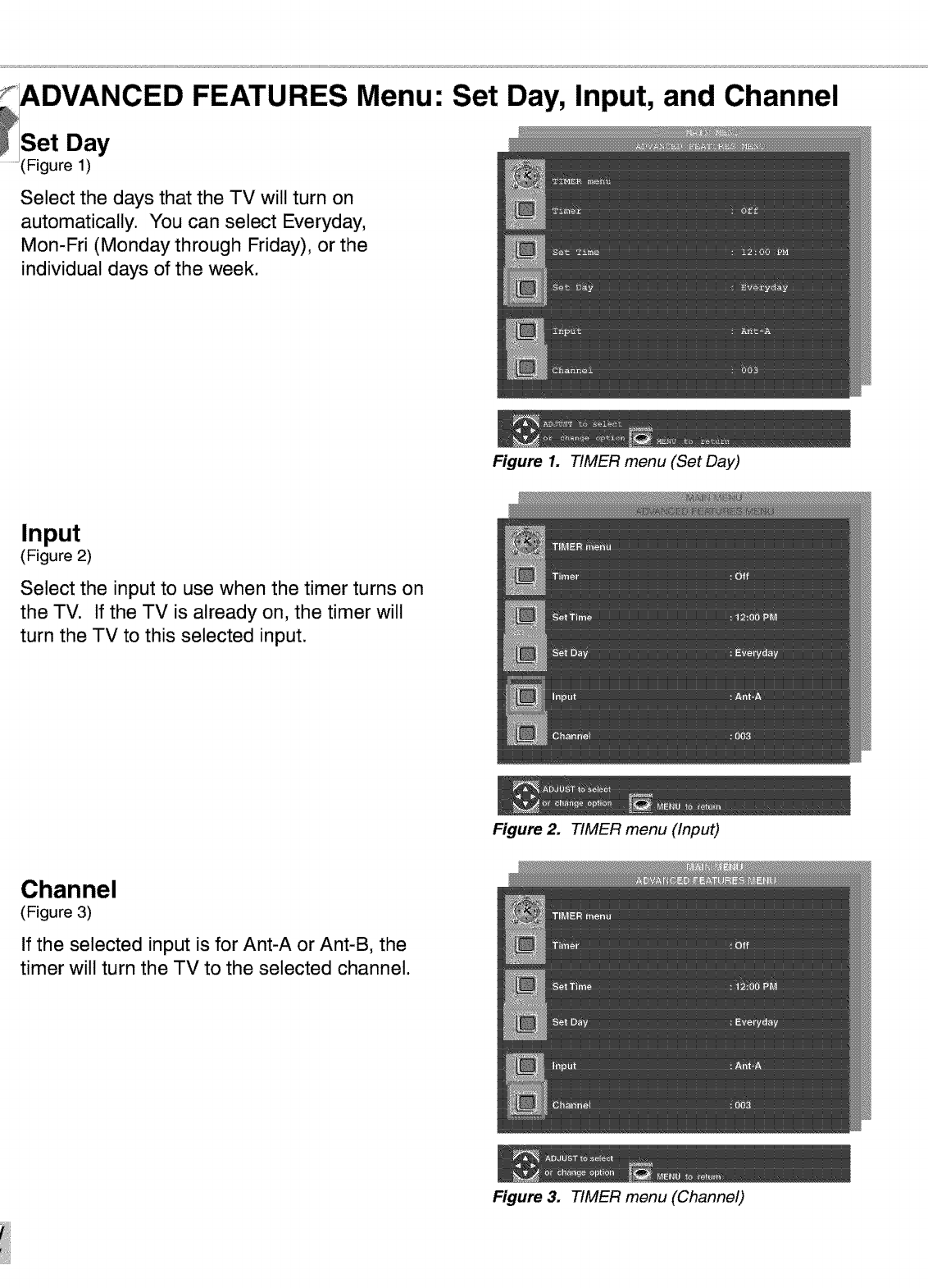
Set Day
(Figure 1)
Select the days that the TV will turn on
automatically. You can select Everyday,
Mon-Fri (Monday through Friday), or the
individual days of the week.
Figure 1. TIMER menu (Set Day)
Input
(Figure 2)
Select the input to use when the timer turns on
the TV. If the TV is already on, the timer will
turn the TV to this selected input.
Figure 2. TIMER menu (Input)
Channel
(Figure 3)
If the selected input is for Ant-A or Ant-B, the
timer will turn the TV to the selected channel.
Figure 3. TIMER menu (Channel)
ADVANCED FEATURES Menu: CONVERGENCE
Part II1: Setup
Figure 1. CONVERGENCE menu
Figure 2. Convergence screen
Figure 3. Advanced Convergence screen
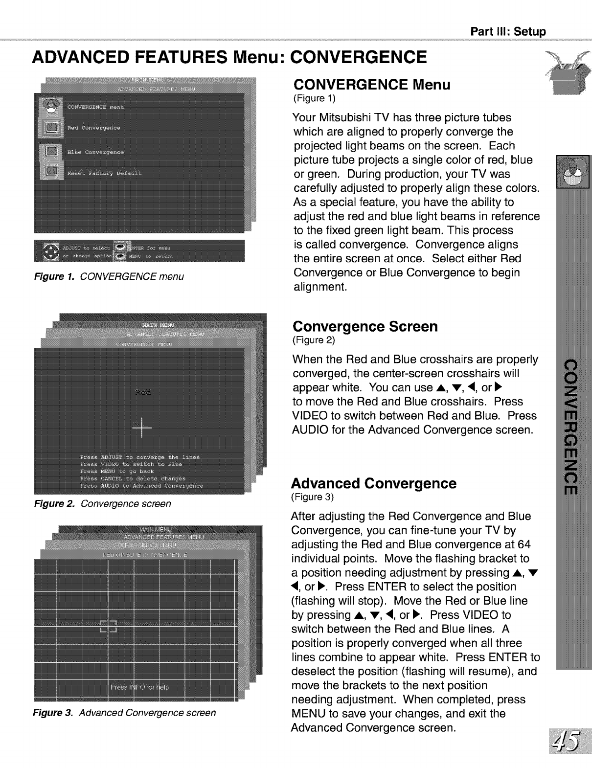
CONVERGENCE Menu
(Figure 1)
Your Mitsubishi TV has three picture tubes
which are aligned to properly converge the
projected light beams on the screen. Each
picture tube projects a single color of red, blue
or green. During production, your TV was
carefully adjusted to properly align these colors.
As a special feature, you have the ability to
adjust the red and blue light beams in reference
to the fixed green light beam. This process
is called convergence. Convergence aligns
the entire screen at once. Select either Red
Convergence or Blue Convergence to begin
alignment.
Convergence Screen
(Figure 2)
When the Red and Blue crosshairs are properly
converged, the center-screen crosshairs will
appear white. You can use A, V, <, or I_
to move the Red and Blue crosshairs. Press
VIDEO to switch between Red and Blue. Press
AUDIO for the Advanced Convergence screen.
Advanced Convergence
(Figure 3)
After adjusting the Red Convergence and Blue
Convergence, you can fine-tune your TV by
adjusting the Red and Blue convergence at 64
individual points. Move the flashing bracket to
a position needing adjustment by pressing A, •
<, or I_. Press ENTER to select the position
(flashing will stop). Move the Red or Blue line
by pressing A, •, <, or I_. Press VIDEO to
switch between the Red and Blue lines. A
position is properly converged when all three
lines combine to appear white. Press ENTER to
deselect the position (flashing will resume), and
move the brackets to the next position
needing adjustment. When completed, press
MENU to save your changes, and exit the
Advanced Convergence screen.
,ADVANCED FEATURES Menu: Reset Convergence, Video
Mute, Black Enhancement
Figure 1. RESET CONVERGENCE TO FACTORY
DEFAULTS
Figure 2. Video Mute/Black Enhancement
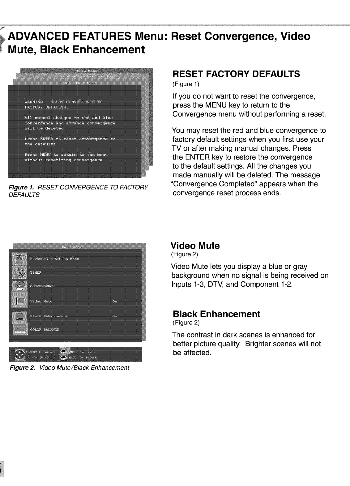
RESET FACTORY DEFAULTS
(Figure 1)
If you do not want to reset the convergence,
press the MENU key to return to the
Convergence menu without performing a reset.
You may reset the red and blue convergence to
factory default settings when you first use your
TV or after making manual changes. Press
the ENTER key to restore the convergence
to the default settings. All the changes you
made manually will be deleted. The message
"Convergence Completed" appears when the
convergence reset process ends.
Video Mute
(Figure 2)
Video Mute lets you display a blue or gray
background when no signal is being received on
Inputs 1-3, DTV, and Component 1-2.
Black Enhancement
(Figure 2)
The contrast in dark scenes is enhanced for
better picture quality. Brighter scenes will not
be affected.
Part II1: Setup
ADVANCED FEATURES Menu: Color Balance
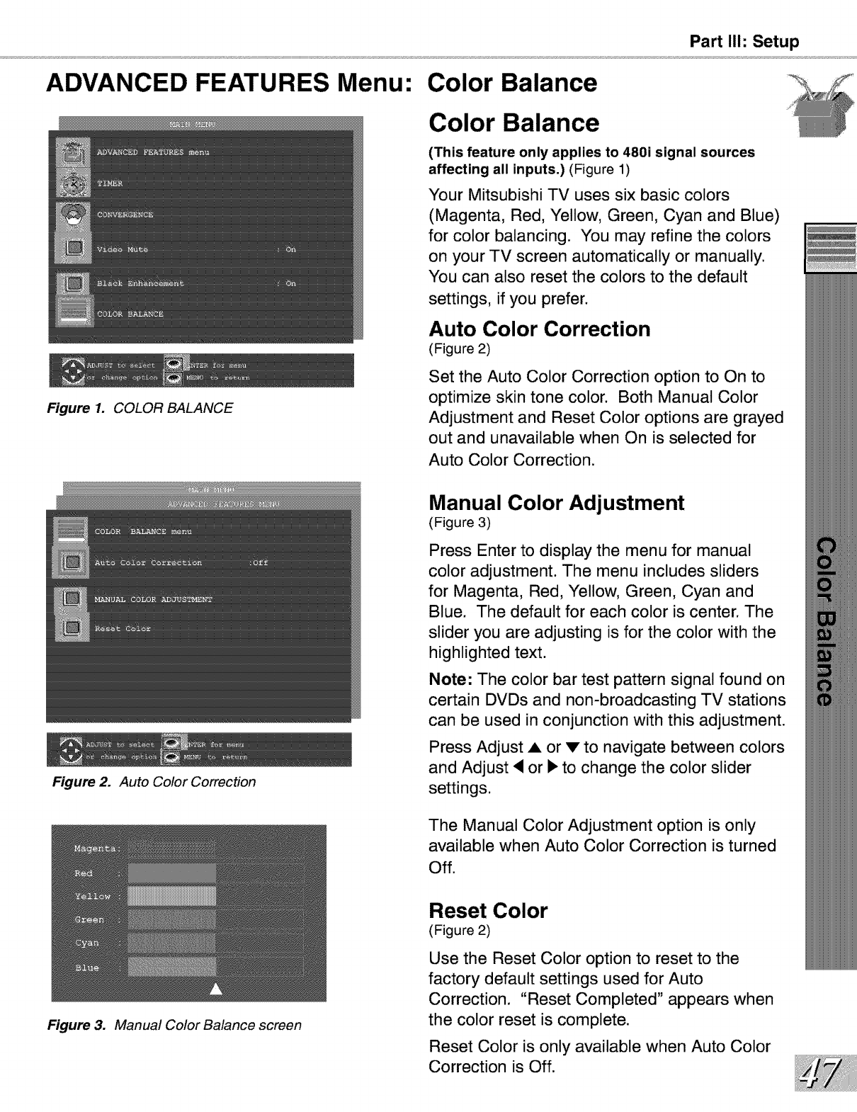
Figure 1. COLOR BALANCE
Figure 2. Auto Color Correction
Color Balance
(This feature only applies to 480i signal sources
affecting all inputs.) (Figure 1)
Your Mitsubishi TV uses six basic colors
(Magenta, Red, Yellow, Green, Cyan and Blue)
for color balancing. You may refine the colors
on your TV screen automatically or manually.
You can also reset the colors to the default
settings, if you prefer.
Auto Color Correction
(Figure 2)
Set the Auto Color Correction option to On to
optimize skin tone color. Both Manual Color
Adjustment and Reset Color options are grayed
out and unavailable when On is selected for
Auto Color Correction.
Manual Color Adjustment
(Figure 3)
Press Enter to display the menu for manual
color adjustment. The menu includes sliders
for Magenta, Red, Yellow, Green, Cyan and
Blue. The default for each color is center. The
slider you are adjusting is for the color with the
highlighted text.
Note: The color bar test pattern signal found on
certain DVDs and non-broadcasting TV stations
can be used in conjunction with this adjustment.
Press Adjust ,& or v to navigate between colors
and Adjust • or • to change the color slider
settings.
The Manual Color Adjustment option is only
available when Auto Color Correction is turned
Off.
Figure 3. Manual Color Balance screen
Reset Color
(Figure 2)
Use the Reset Color option to reset to the
factory default settings used for Auto
Correction. "Reset Completed" appears when
the color reset is complete.
Reset Color is only available when Auto Color
Correction is Off.
AUDIO/VIDEO SETTINGS Menu: Audio Output
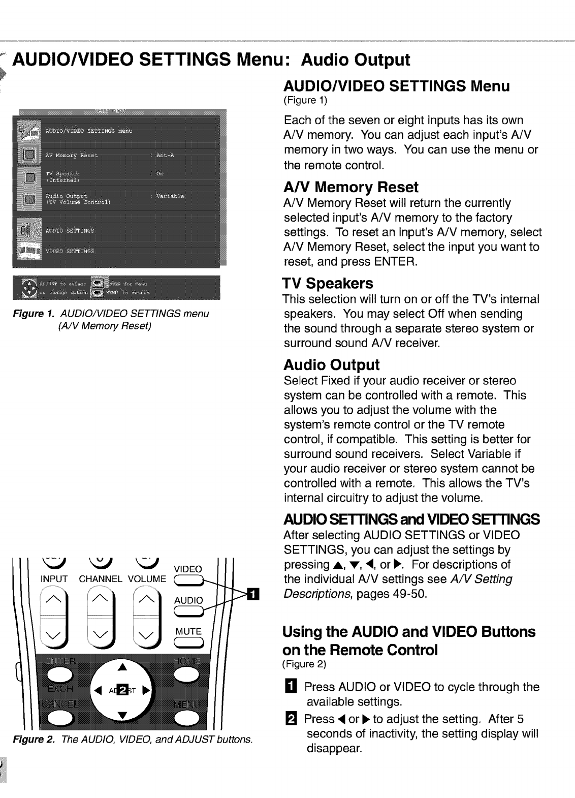
AUDIO/VIDEO SETTINGS Menu
(Figure 1)
Each of the seven or eight inputs has its own
AiV memory. You can adjust each input's AiV
memory in two ways. You can use the menu or
the remote control.
Figure 1. AUDIO/VIDEO SETTINGS menu
(A/V Memory Reset)
A/V Memory Reset
AiV Memory Reset will return the currently
selected input's AiV memory to the factory
settings. To reset an input's AiV memory, select
AiV Memory Reset, select the input you want to
reset, and press ENTER.
TV Speakers
This selection will turn on or off the TV's internal
speakers. You may select Off when sending
the sound through a separate stereo system or
surround sound AiV receiver.
INPUT CHANNEL VOLUME VIDEO
Figure 2. The AUDIO, VIDEO, and ADJUST buttons.
Audio Output
Select Fixed if your audio receiver or stereo
system can be controlled with a remote. This
allows you to adjust the volume with the
system's remote control or the TV remote
control, if compatible. This setting is better for
surround sound receivers. Select Variable if
your audio receiver or stereo system cannot be
controlled with a remote. This allows the TV's
internal circuitry to adjust the volume.
AUDIO SETTINGS and VIDEO SE-I'rlNGS
After selecting AUDIO SETTINGS or VIDEO
SETTINGS, you can adjust the settings by
pressing A, V, •, or •. For descriptions of
the individual AiV settings see A/V Setting
Descriptions, pages 49-50.
Using the AUDIO and VIDEO Buttons
on the Remote Control
(Figure 2)
0Press AUDIO or VIDEO to cycle through the
available settings.
[] Press • or • to adjust the setting. After 5
seconds of inactivity, the setting display will
disappear.
A/V Setting Descriptions: Audio
Part II1: Setup
Audio Settings
[] Bass enhances or reduces low frequency
sound.
Treble enhances or reduces high frequency
sound.
Balance adjusts the level of sound between
the left and right speakers.
Surround creates simulated stereo and
surround effects. Your choices are:
• Off: No surround effects. Use this
setting when using an AiV receiver with
Dolby TM Pro Logic Surround, or Dolby TM
Digital Surround.
• Simulated Stereo: Your TV will create a
simulated stereo effect when watching a
non-stereo program.
• Surround Sound: Your TV will create a
simulated surround effect when watching
a stereo program.
Listen to (for Ant-A and Ant-B) determines
how your TV will receive a broadcast audio
signal and play back the sound you hear.
Your choices are:
• Stereo: Default setting. The TV will play
stereo broadcasts in stereo and mono
broadcasts in mono. The word "Stereo"
will be displayed when you tune to a
channel broadcasting stereo.
• SAP (Second Audio Program):
Additional monaural soundtrack that you
cannot hear during normal TV viewing.
The SAP signal might be related to the
program you are watching, such as a
soundtrack in a foreign language, or
unrelated to the program you are
watching such as a weather report. If a
SAP signal is broadcast, the letters "SAP"
will be displayed when you tune to the
channel.
• Mono: Reduces background noise and
should be used when receiving a weak
stereo audio signal. All audio will be
played mono with this setting.
Listen to (for INPUTs) is not available.
Level Sound automatically equalizes
the volume level of programs containing
significant level differences from one
segment to another (for example, regular
programming to commercials). To receive
the best fidelity with music programs, you
can turn this setting to Off.
A/V Setting Descriptions:
Video Settings
Video
€= Contrast provides a slider to adjust the
white-to-black level. Low contrast shows a
variety of shades in darker images, while
high contrast shows darker images more
uniformly black and makes colors appear
more vibrant.
Brightness provides a slider to adjust the
overall brightness of the picture.
Sharpness provides a slider to adjust the
detail and clarity.
[] Color provides a slider to adjust the color
intensity.
Tint provides a slider to adjust the
proportion of red to green.
Color Temp (Color Temperature) allows
you to adjust how white images are
displayed. Your choices are:
• Low 6500K or Low (for DTV): White
images will have a warm cast to them.
This adjustment is an average and can
vary due to ambient room lighting, video
scene brightness and the TV's age.
The Low 6500K represents the 6500K
industry standard for NTSC (non-DTV)
pictures.
•Medium: White images will be balanced
between the Low (warm) and High (cool)
settings.
• High: White images will have a cool cast
to them. This setting may provide the
most realistic picture under bright lighting.
Video Noise reduces minor noise
(graininess) in the broadcast or input signal.
Film Mode (Automatic)
Video media uses a video camera created at
30 frames per second. Film media uses a
film camera created at 24 frames per second.
Examples of video media are live TV broadcast
such as news, special events, or video taped
programs. Examples of film media are motion
pictures, made-for-TV movies, and many prime
time programs. Filmed media is converted by
the broadcaster or home video company to
30 frames per second to match TV or video
standards. This conversion can leave subtle
"picture artifacts" or conversion errors.
The settings are On and Off. If you select
On, the system automatically detects if the
signal source is Film and corrects for conversion
errors. If you select Off, the system will never
correct for conversion errors.
Velocity Scanning Modulation
(VSM) Sharpness
When turned On selected image outlines are
emphasized, resulting in sharper images.
The default is On. When turned Off, the velocity
scanning modulation function is prevented.
Part II1: Setup
Warning: Do not leave stationary or letterbox images on-screen for
extended periods of time. Mix the types of pictures shown.
Uneven picture tube aging is NOT covered by your warranty.
The normal use of a TV should include a
mixture of TV picture types. The most
frequently used picture types should fill the
screen with constantly moving images rather
than stationary images or patterns. Displaying
the same stationary patterns over extended
periods of time or displaying the same
stationary pattern frequently may leave a
subtle but permanent ghost image. To avoid
this, mix your viewing pattern. Do not show
the same stationary image for more than 15%
of your total TV viewing in any given week.
Display constantly moving and changing
images that fill the screen whenever possible.
This projection TV uses picture tubes to project
the image to the screen. All picture tubes
age with use. As they age, their light output
is gradually reduced. Normal TV pictures fill
the screen with constantly changing images.
Under these conditions, picture tubes age at
an even rate across the entire screen. This
maintains a TV picture that is evenly bright
over the whole screen. Stationary images
or images that only partially fill the screen
(leaving black or colored bars to fill the screen),
when used over extended periods of time or
when viewed repeatedly may cause uneven
aging of the phosphors and leave subtle
ghosts of the stationary images in the picture.
Still or stationary images may be received
from broadcasters, cable channels, satellite
channels, DVD discs, video tapes, laser
discs, on-line services, webilnternet
searching devices, video games, and digital
TV tuner/converter boxes. Examples of these
types of images can be, but are not limited to
the following:
[] Letterbox top/bottom black bars:
shown at the top and bottom of the TV
screen when you watch a widescreen
(16:9) movie on a standard (4:3) TV.
Side bar images: solid bars shown
on each side of an image when
watching a standard (4:3) program on
a widescreen (16:9) TV.
Stock-market report bars: ticker
running at the bottom of the TV
screen.
Shopping channel Iogos & pricing
displays: bright graphics that are
shown constantly or repeatedly in the
same location.
Video game patterns and scoreboards
Bright station Iogos: moving or
low-contrast graphics are less likely
to cause uneven aging of the picture
tubes.
Online (Internet) websites: or any other
stationary or repetitive computer style
images.
Closed Captioning

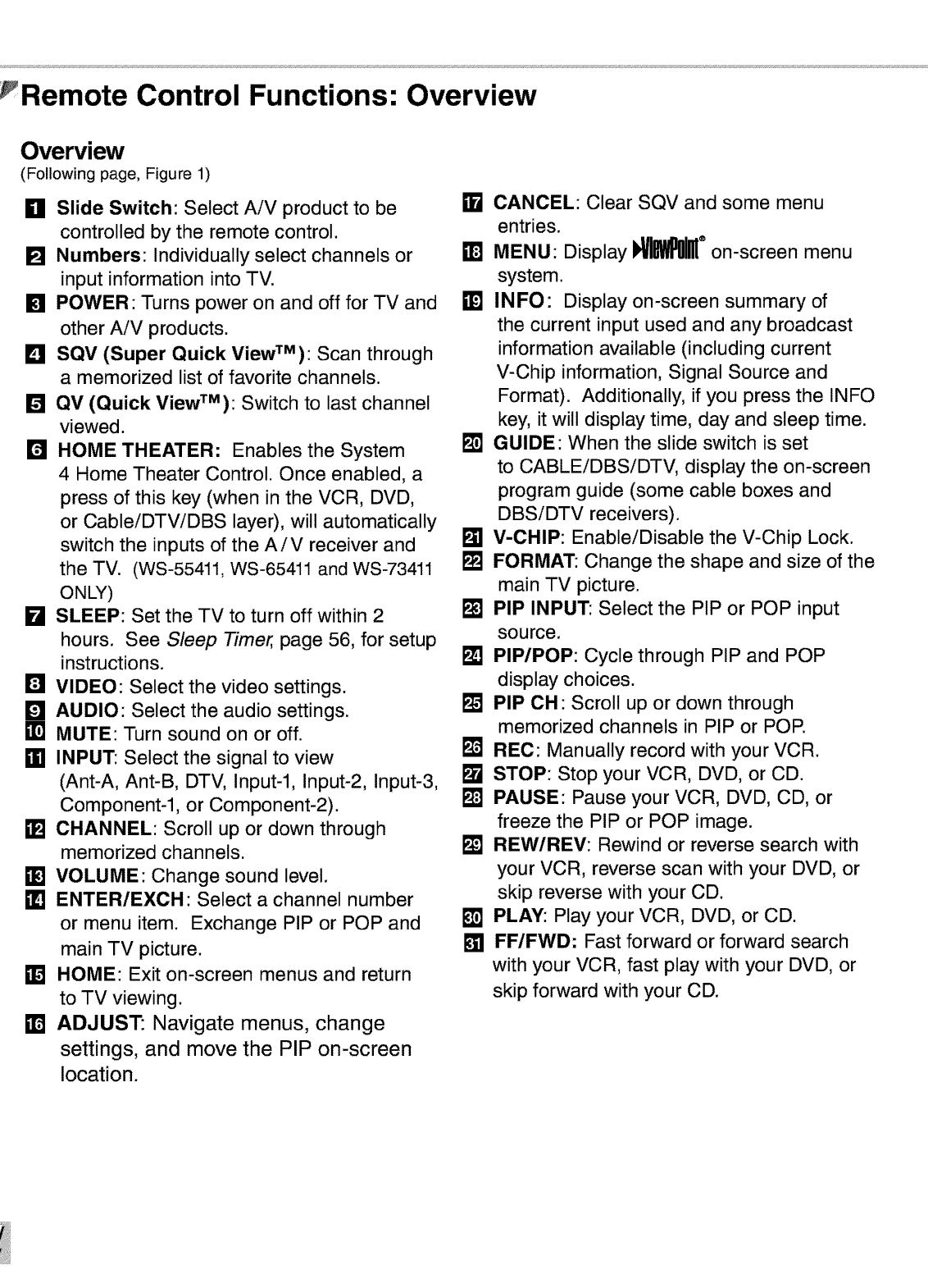
rRemote Control Functions: Overview
Overview
(Following page, Figure 1)
gll Slide Switch: Select AiV product to be
controlled by the remote control.
[] Numbers: Individually select channels or
input information into TV.
[] POWER: Turns power on and off for TV and
other AiV products.
L_I SQV (Super Quick ViewTM): Scan through
amemorized list of favorite channels.
[] QV (Quick ViewTM): Switch to last channel
viewed.
I'R HOME THEATER: Enables the System
4 Home Theater Control. Once enabled, a
press of this key (when in the VCR, DVD,
or CableiDTViDBS layer), will automatically
switch the inputs of the AiV receiver and
the TV. (WS-55411, WS-65411 and WS-73411
ONLY)
kl SLEEP: Set the TV to turn off within 2
hours. See Sleep Timer, page 56, for setup
instructions.
IN VIDEO: Select the video settings.
1121AUDIO: Select the audio settings.
•1 MUTE: Turn sound on or off.
ffl INPUT: Select the signal to view
(Ant-A, Ant-B, DTV, Input-l, Input-2, Input-3,
Component-I, or Component-2).
[] CHANNEL: Scroll up or down through
memorized channels.
• ] VOLUME: Change sound level.
ml ENTER/EXCH: Select a channel number
or menu item. Exchange PIP or POP and
main TV picture.
•1HOME: Exit on-screen menus and return
to TV viewing.
mADJUST: Navigate menus, change
settings, and move the PIP on-screen
location.
CANCEL: Clear SQV and some menu
entries.
MENU" Display !_I_M_ ®on-screen menu
system.
•1INFO: Display on-screen summary of
the current input used and any broadcast
information available (including current
V-Chip information, Signal Source and
Format). Additionally, if you press the INFO
key, it will display time, day and sleep time.
I_J GUIDE: When the slide switch is set
to CABLEiDBSiDTV, display the on-screen
program guide (some cable boxes and
DBSiDTV receivers).
[] V-CHIP: Enable/Disable the V-Chip Lock.
k'_ FORMAT: Change the shape and size of the
main TV picture.
k'_ PIP INPUT: Select the PIP or POP input
source.
I_ PIP/POP: Cycle through PIP and POP
display choices.
k'_ PIP OH: Scroll up or down through
memorized channels in PIP or POP.
Ft_JREC: Manually record with your VCR.
k'_ STOP: Stop your VCR, DVD, or CD.
F'_ PAUSE: Pause your VCR, DVD, CD, or
freeze the PIP or POP image.
k'_ REW/REV: Rewind or reverse search with
your VCR, reverse scan with your DVD, or
skip reverse with your CD.
[] PLAY: Play your VCR, DVD, or CD.
[] FF/FWD: Fast forward or forward search
with your VCR, fast play with your DVD, or
skip forward with your CD.
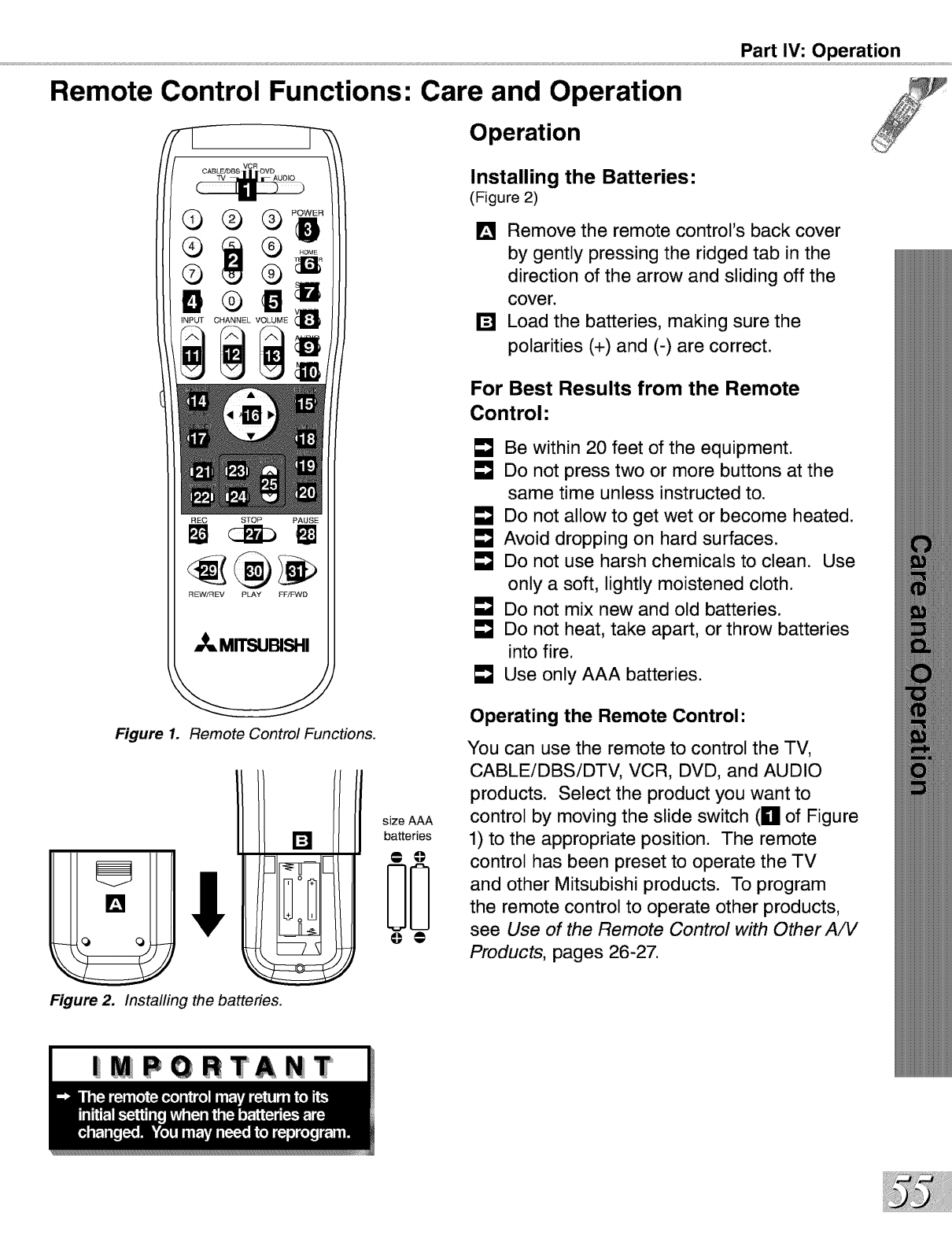
Part IV: Operation
Remote Control Functions: Care and Operation
REC STOP PAUSE
REW/REV PLAY FFIFWD
_MITSUBISHI
Figure 1. Remote Control Functions.
I ;fsze A
[] batteries
O0
Figure 2. Installing the batteries.
Operation
Installing the Batteries:
(Figure 2)
[] Remove the remote control's back cover
by gently pressing the ridged tab in the
direction of the arrow and sliding off the
cover.
[] Load the batteries, making sure the
polarities (+) and (-) are correct.
For Best Results from the Remote
Control"
LmJBe within 20 feet of the equipment.
E"J Do not press two or more buttons at the
same time unless instructed to.
LmJDo not allow to get wet or become heated.
LmJAvoid dropping on hard surfaces.
LmJDo not use harsh chemicals to clean. Use
only a soft, lightly moistened cloth.
LmJDo not mix new and old batteries.
LmJDo not heat, take apart, or throw batteries
into fire.
LmJUse only AAA batteries.
Operating the Remote Control:
You can use the remote to control the TV,
CABLEiDBSiDTV, VCR, DVD, and AUDIO
products. Select the product you want to
control by moving the slide switch (g of Figure
1) to the appropriate position. The remote
control has been preset to operate the TV
and other Mitsubishi products. To program
the remote control to operate other products,
see Use of the Remote Control with Other A/V
Products, pages 26-27.
| PORTANT
Remote Control Functions: Channel Selection, Sleep Timer
Channel Selection
For Non-DTV Channels:
[]
or
or
Enter three numbers (for channel 2, press
002).
Press the channel number and ENTER (for
channel 2, press 2, then ENTER).
Enter the channel number and wait four
seconds. The TV will change automatically.
Sleep Timer
Setting the Sleep Timer:
Press SLEEP on the remote control.
A message indicating the length of time
the sleep timer is to be set appears on
the TV screen.
Each press of SLEEP will increase
the time displayed by 30 minutes, until
the maximum value of 120 minutes is
reached.
After 5 seconds of inactivity, the
message will disappear.
Press SLEEP to view the remaining time
before the timer turns the TV off.
Canceling the Sleep Timer:
Press SLEEP to display the on-screen
message.
Press SLEEP repeatedly until OFF is
displayed. After 5 seconds of inactivity,
the message will disappear.
Remote Control Functions:
System 4 Home Theater IR
Part IV: Operation
Control (ws-55411,WS-65411 and WS-73411 ONLY)
The Mitsubishi Home Theater IR System
Control is a special feature that makes it easier
to use your TV with a Mitsubishi digital AiV
receiver. Once your equipment is properly
connected and set up, your TV and Mitsubishi
digital AiV receiver will change inputs together,
to match high resolution pictures with the proper
surround sound. See How Connections Affect
the System 4 Home Theater IR Control, Pages
14-15, for installation instructions.
When you change inputs on your TV to watch
different video products, your TV will send
signals via the infrared emitter to your Mitsubishi
digital AiV receiver and will also change inputs
to hear the sound from that product. You
will automatically hear the high quality digital
surround sound from digital products like your
DTV receiver and DVD, and high quality analog
stereo or surround sound from non-digital
products like your VCR.
As you change TV inputs, the AiV receiver
changes its source for sound.
Remote Control Functions: Special Functions
When your remote control has been Programmed to operate another manufacturer's
)roduct, the function performed on each layer may vary. The most common functions are:
• POWER • PLAY • PAUSE • FF/FWD
• CHANNEL up/down •REC •STOP • REW/REV
• POWER • ENTER (on some models) •ADJUST up/down/left/right
• CHANNEL up/down •CANCEL (on some models) (on some models)
• 0-9 Number Buttons (on some models) • GUIDE (on some models)
• POWER •VOLUME • MUTE
• Direct Input Selection Buttons -use number buttons, SQV, and QV (on some models)
• PLAY • FF/FWD • REW/REV • PAUSE •STOP
• POWER •PLAY •ARROW up/down/left/right •PAUSE •CANCEL (on some models)
• MENU •STOP (on some models) •REW/REV •ENTER
• 0-9 Number Buttons (on some models)
Remote Control Functions: Operation of PIP and POP
Picture-In-Picture (PIP) and Picture-Outside-
Picture (POP) features allow you to view
Programming in different ways. While watching
the main screen, you can display programs from
other channels and other inputs. To see which
inputs can and cannot be used together, see
How Connections Affect the PIP and POP -
Table 1, page 14. You can display large and
small PIPs, side-by-side pictures, three POPs,
or nine POPs.
Activating the PIP and POP
Figures 1-4 on following page/Figure 1-5 on page 62
Press PIP/POP to choose a display format.
Each time the PIP/POP button is pressed on
the TV remote control (within 3 seconds of each
other), the PIP/POP cycles through the following
display options.
n POP: side-by-side pictures
[] POP: three POPs
[] PIP: large PIP
I_1 PIP: small PIP
[] POP: nine POPs (Widescreen models Only)
To turn PIP/POP Off, wait at least 10 seconds,
and press PIP/POE The next time you activate
PIP/POP, the last used PIP/POP format will be
displayed first.
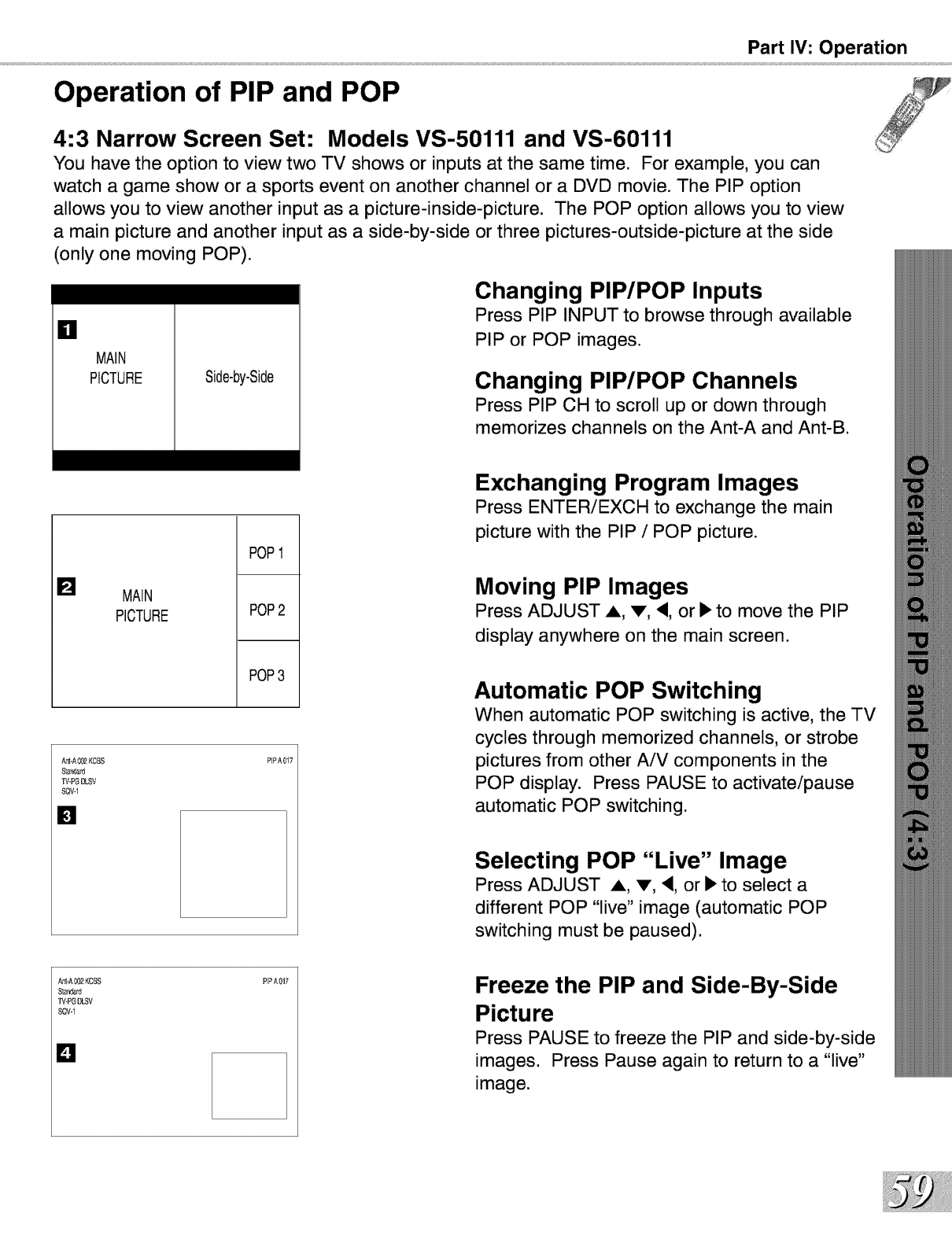
Part IV: Operation
Operation of PIP and POP
4:3 Narrow Screen Set: Models VS-50111 and VS-60111
You have the option to view two TV shows or inputs at the same time. For example, you can
watch agame show or a sports event on another channel or a DVD movie. The PIP option
allows you to view another input as a picture-inside-picture. The POP option allows you to view
amain picture and another input as a side-by-side or three pictures-outside-picture at the side
(only one moving POP).
=1
MAIN
PICTURE Side-by-Side
Changing PIP/POP Inputs
Press PIP INPUT to browse through available
PIP or POP images.
Changing PIP/POP Channels
Press PIP CH to scroll up or down through
memorizes channels on the Ant-A and Ant-B.
[] MAIN
PICTURE
POP
POP
POP3
Ar_-A002KCBS
$[ar_ard
%_-PGDLSV
SQV-1
[]
PIPA017
Exchanging Program Images
Press ENTERiEXCH to exchange the main
picture with the PIP /POP picture.
Moving PIP Images
Press ADJUST A, v, <, or •to move the PIP
display anywhere on the main screen.
Automatic POP Switching
When automatic POP switching is active, the TV
cycles through memorized channels, or strobe
pictures from other AiV components in the
POP display. Press PAUSE to activate/pause
automatic POP switching.
Selecting POP "Live" Image
Press ADJUST A, v, <, or • to select a
different POP "live" image (automatic POP
switching must be paused).
SQV-i
D
PIPA017 Freeze the PIP and Side-By-Side
Picture
Press PAUSE to freeze the PIP and side-by-side
images. Press Pause again to return to a "live"
image.
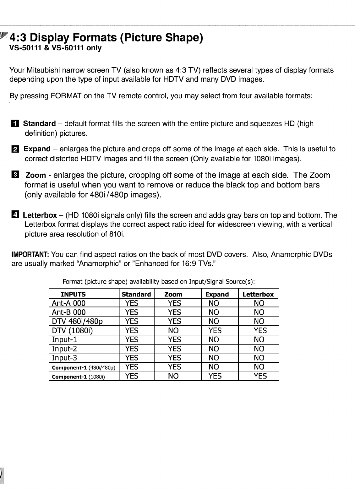
4:3 Display Formats (Picture Shape)
VS-50111 & VS-60111 only
Your Mitsubishi narrow screen TV (also known as 4:3 TV) reflects several types of display formats
depending upon the type of input available for HDTV and many DVD images.
By pressing FORMAT on the TV remote control, you may select from four available formats:
ml
[]
[]
[]
Standard - default format fills the screen with the entire picture and squeezes HD (high
definition) pictures.
Expand - enlarges the picture and crops off some of the image at each side. This is useful to
correct distorted HDTV images and fill the screen (Only available for 1080i images).
Zoom - enlarges the picture, cropping off some of the image at each side. The Zoom
format is useful when you want to remove or reduce the black top and bottom bars
(only available for 480i/480p images).
Letterbox - (HD 1080i signals only) fills the screen and adds gray bars on top and bottom. The
Letterbox format displays the correct aspect ratio ideal for widescreen viewing, with a vertical
picture area resolution of 810i.
IMPORTANT:You can find aspect ratios on the back of most DVD covers. Also, Anamorphic DVDs
are usually marked "Anamorphic" or "Enhanced for 16:9 TVs."
Format (picture shape) availability based on Input/Signal Source(s):
INPUTS Standard Zoom Expand Letterbox
Ant-A 000 YES YES NO NO
Ant-B 000 YES YES NO NO
DTV 480i/480p YES YES NO NO
DTV (1080i) YES NO YES YES
Input-1 YES YES NO NO
Input-2 YES YES NO NO
Input-3 YES YES NO NO
Component-1 (480i/480p) YES YES NO NO
Component-1 (1080i) YES NO YES YES
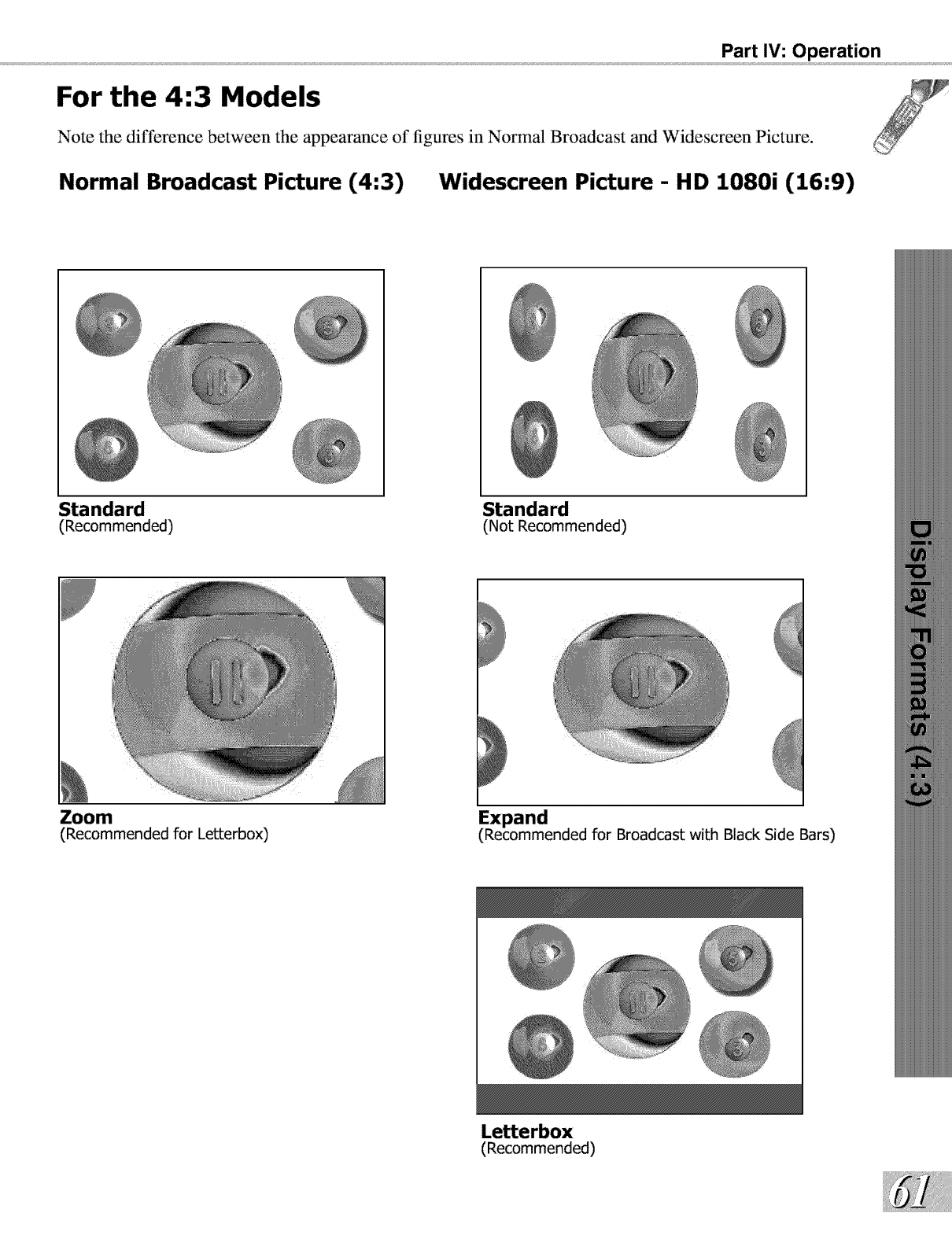
Part IV: Operation
For the 4:3 Models
Note the difference between the appearance of figures in Normal Broadcast and Widescreen Picture.
Normal Broadcast Picture (4:3) Widescreen Picture - HD 1080i (16:9)
Standard
(Recommended)
Zoom
(Recommended for Letterbox)
Standard
(Not Recommended)
Expand
(Recommended for Broadcast with Black Side Bars)
Letterbox
(Recommended)
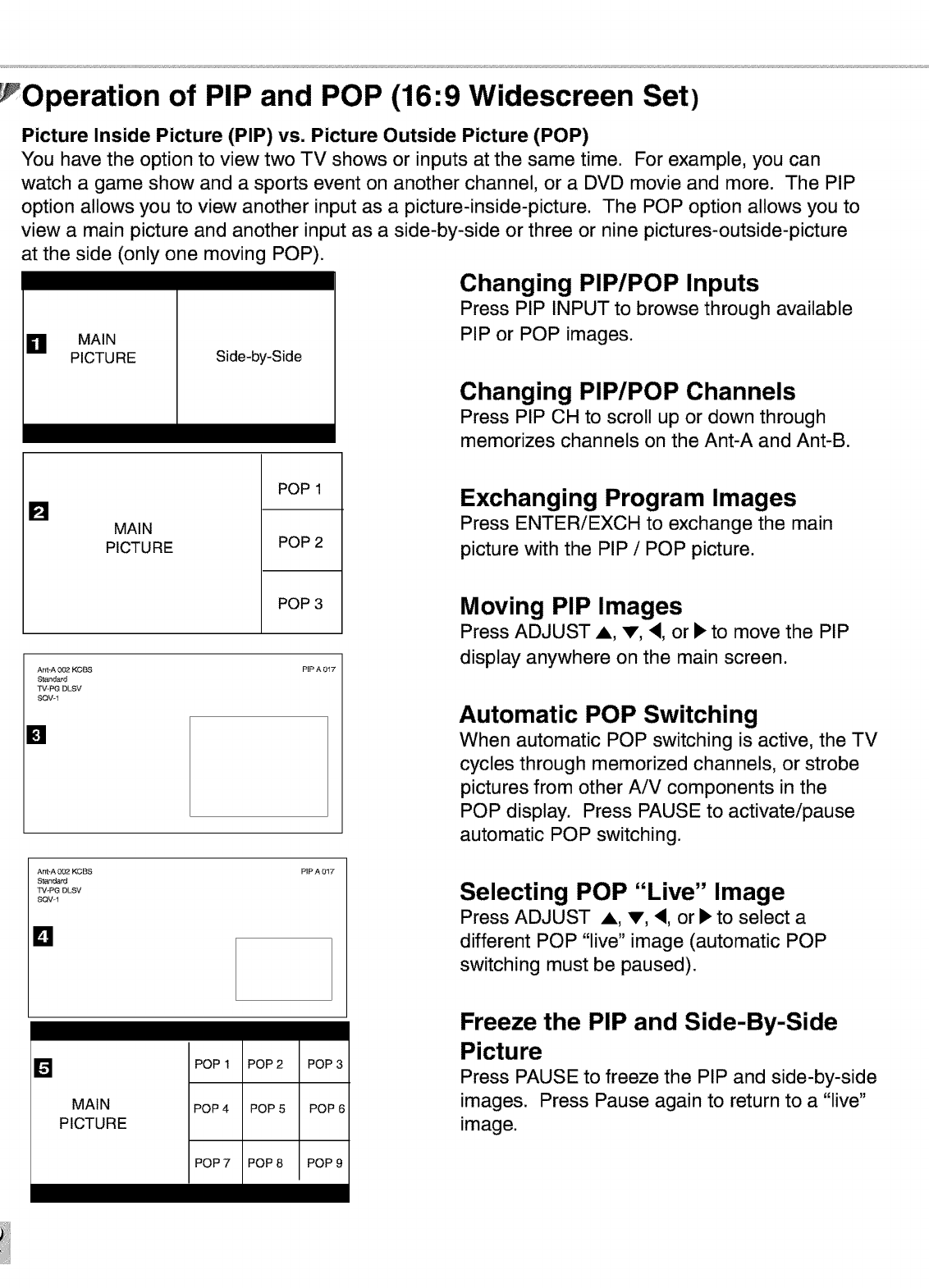
Operation of PIP and POP (16:9 Widescreen Set)
Picture Inside Picture (PIP) vs. Picture Outside Picture (POP)
You have the option to view two TV shows or inputs at the same time. For example, you can
watch a game show and a sports event on another channel, or a DVD movie and more. The PIP
option allows you to view another input as a picture-inside-picture. The POP option allows you to
view a main picture and another input as a side-by-side or three or nine pictures-outside-picture
at the side (only one moving POP).
Changing PIP/POP Inputs
Press PIP INPUT to browse through available
PIP or POP images.
Side-by-Side
OMAIN
PICTURE
Changing PIP/POP Channels
Press PIP CH to scroll up or down through
memorizes channels on the Ant-A and Ant-B.
[] MAIN
PICTURE
POP 1
POP 2
POP 3
Ant-A 002 KCBS
S_andard
TV-PG DLSV
SQVq
[]
PIPA 012"
Ant-A 00_2KCBS
Standard
TV-I_G DLSV
SQV-1
PIPA 012"
Lq
Exchanging Program Images
Press ENTERiEXCH to exchange the main
picture with the PIP /POP picture.
Moving PIP Images
Press ADJUST A, V, <, or • to move the PIP
display anywhere on the main screen.
Automatic POP Switching
When automatic POP switching is active, the TV
cycles through memorized channels, or strobe
pictures from other AiV components in the
POP display. Press PAUSE to activate/pause
automatic POP switching.
Selecting POP "Live" Image
Press ADJUST A, V, <, or • to select a
different POP "live" image (automatic POP
switching must be paused).
[]
MAIN
PICTURE
POP 1
POP 4
POP 2
POP 5
POP 3
POP 6
Freeze the PIP and Side-By-Side
Picture
Press PAUSE to freeze the PIP and side-by-side
images. Press Pause again to return to a "live"
image.
POP 7 POP 8 POP 9
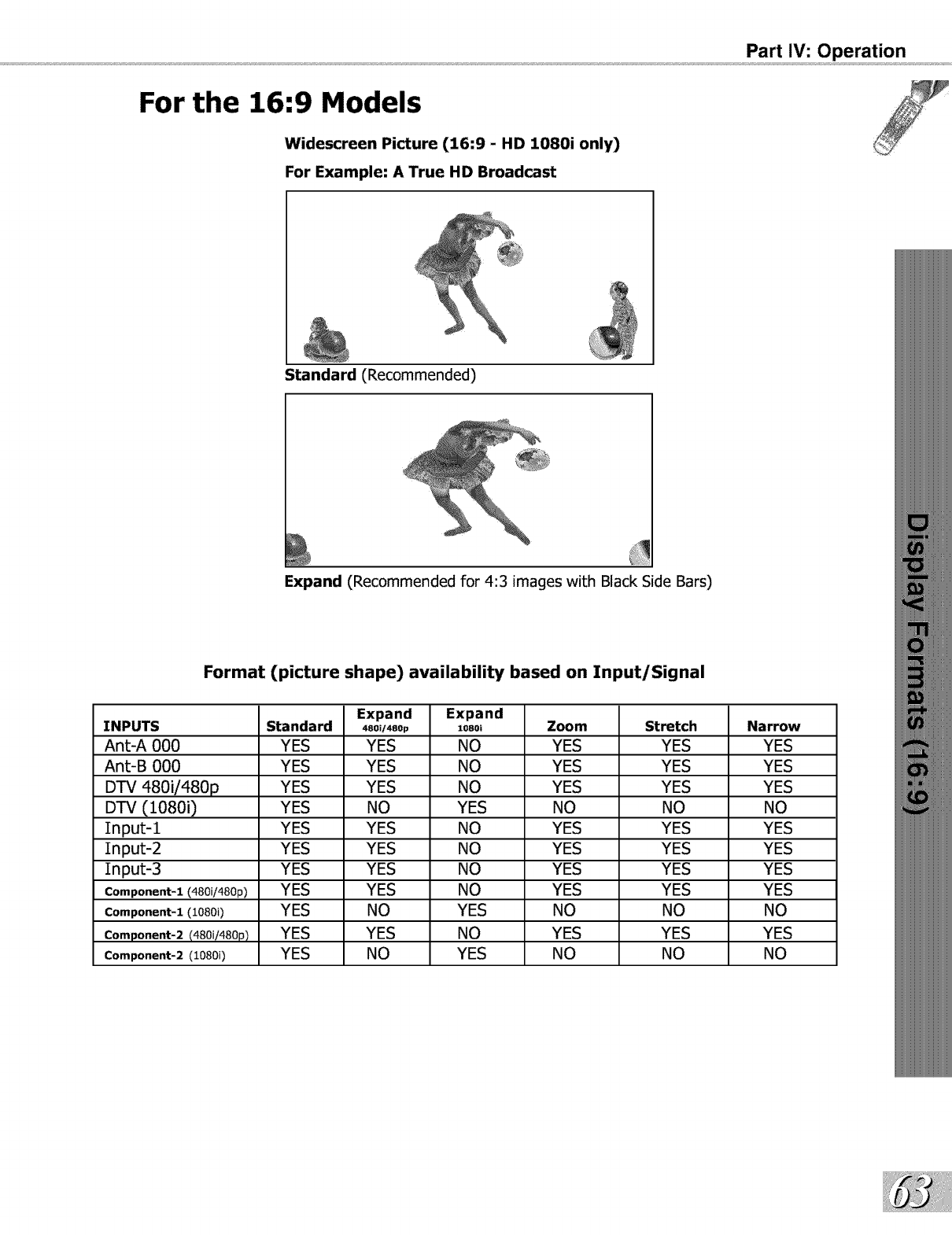
For the 16:9 Models
Widescreen Picture (16:9 - HD 1080i only)
For Example: A True HD Broadcast
Part IV: Operation
Standard (Recommended)
Expand (Recommended for 4:3 images with Black Side Bars)
Format (picture shape) availability based on Input/Signal
Expand Expand
INPUTS Standard 48oi/48op lo8oi Zoom Stretch Narrow
AnL-A 000 YES YES NO YES YES YES
Ant-B 000 YES YES NO YES YES YES
DTV 480i/480p YES YES NO YES YES YES
DTV (1080i) YES NO YES NO NO NO
Input-1 YES YES NO YES YES YES
Input-2 YES YES NO YES YES YES
Input-3 YES YES NO YES YES YES
Component-1 (480i/480p) YES YES NO YES YES YES
Component-1(10800 YES NO YES NO NO NO
Component-2(480i/480p) YES YES NO YES YES YES
Component-2(10800 YES NO YES NO NO NO
6:9 Display Formats (Picture Shape)
Wide Screen Models Only
Your Mitsubishi widescreen TV (also known as 16:9 TV) reflects several types of display formats
(picture shape) available for HDTV and many DVD images.
By pressing FORMAT on the TV remote control, you may select from six available formats:
g Standard - default format for DTV and Component Input displays a full-screen format. The
Standard format displays Anamorphic DVDs that have the 1.78:1 or 1.85:1 aspect ratios.
However, Anamorphic DVDs that have the 2.35:1 aspect ratio still display black bars at the top
and bottom of the screen, while narrow (4:3) images are stretched evenly from side to side.
[] Expand (480i/480p)- enlarges the picture, cropping some of the image at the top and bottom.
The Expand format is useful to reduce the letterbox top and bottom bars of non-Anamorphic
DVDs or to correct narrow 4:3 images that have been stretched in the Standard format.
Note: This format is not available in the 1080i format.
[] Expand (1080i) - enlarges the picture, cropping some of the image on both sides. This Expand
format is useful to remove or reduce black side bars on HD broadcasts of 4:3 images with
black bars (See page 63).
[] Zoom - enlarges the picture, cropping some of the image at each side, top and bottom. The
Zoom format is useful to remove or reduce the black top and bottom bars on Anamorphic
DVDs with 2.35:1 aspect ratio.
Note: This format is not available in the 1080i signal.
[] Stretched - is the default format for ANT-A and Ant-B, and Inputs 1-3. The Stretched format
stretches narrow 4:3 images across the screen, however, there is less stretch in the center
than the sides. The Stretched format allows the entire narrow image to be displayed across
the screen, however, there is less distortion in the center than in the sides.
Note: This format is not available in the 1080i signal.
[] Narrow format displays narrow 4:3 images in their original shape and adds stationary gray side
bars to fill the screen. Note: This format is not available in the 1080i signal.
IMPORTANT: You can find aspect ratios on the back of most DVD covers. Also, Anamorphic
DVDs are usually marked "Anamorphic" or "Enhanced for 16:9 TVs."
|MPGRTANT
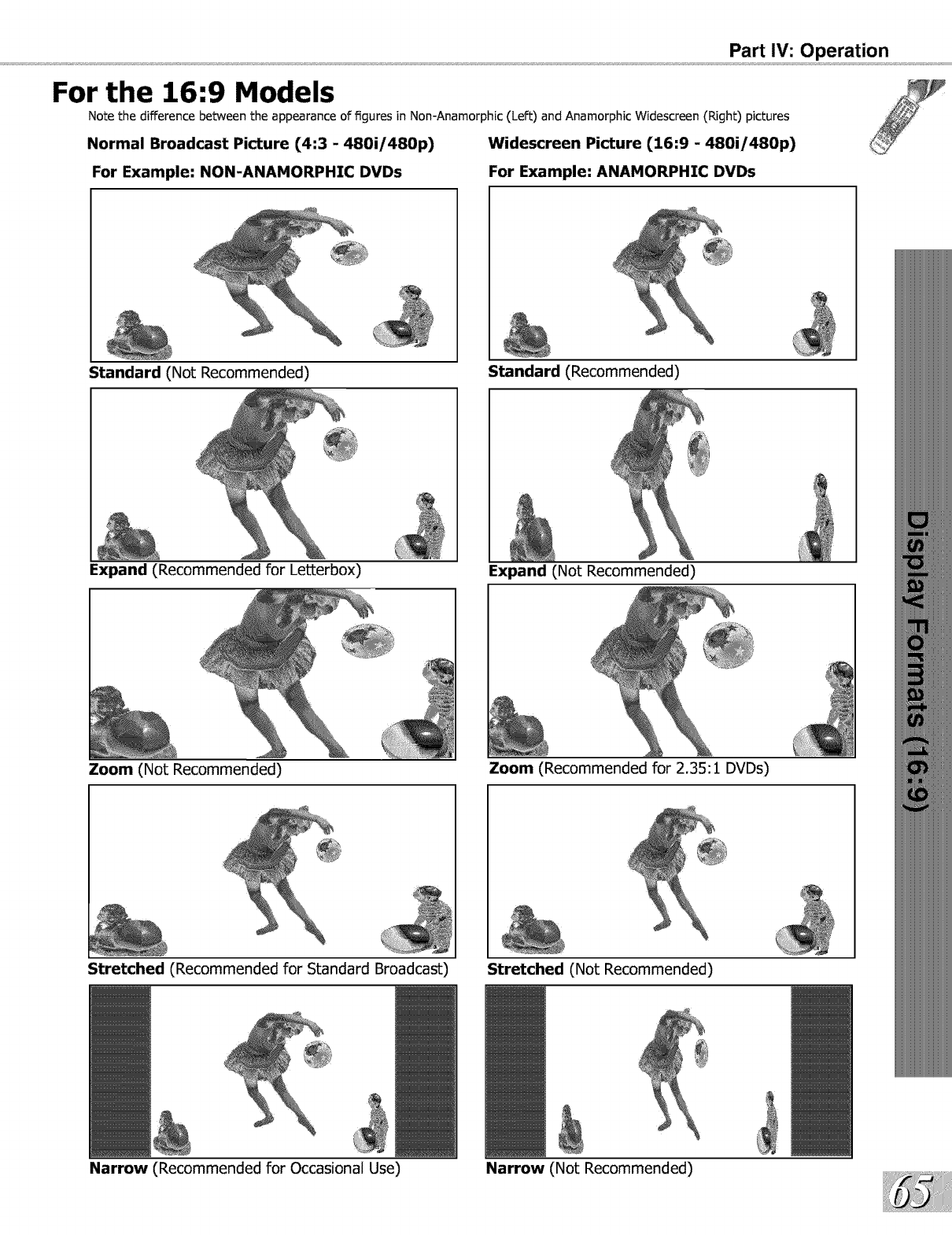
Part IV: Operation
For the 16:9 Models
Note the difference between the appearance of figures in Non-Anamorphic (Left) and Anamorphic Widescreen (Right) pictures
Normal Broadcast Picture (4:3 -480i/480p) Widescreen Picture (16:9 -480i/480p)
For Example: NON-ANAMORPHIC DVDs For Example: ANAMORPHIC DVDs
Standard (Not Recommended) Standard (Recommended)
Expand (Recommended for LetLerbox) Expand (Not Recommended)
Zoom (Not Recommended) Zoom (Recommended for 2.35:1 DVDs)
Stretched (Recommended for Standard Broadcast) Stretched (Not Recommended)
Narrow (Recommended for Occasional Use) Narrow (Not Recommended)
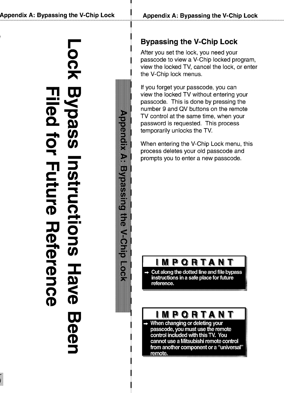
Appendix A: Bypassing the V-Chip Lock
=====
(1)
Appendix A: Bypassing the V-Chip Lock
Bypassing the V-Chip Lock
After you set the lock, you need your
passcode to view a V-Chip locked program,
view the locked TV, cancel the lock, or enter
the V-Chip lock menus.
If you forget your passcode, you can
view the locked TV without entering your
passcode. This is done by pressing the
number 9 and QV buttons on the remote
TV control at the same time, when your
password is requested. This process
temporarily unlocks the TV.
When entering the V-Chip Lock menu, this
process deletes your old passcode and
prompts you to enter a new passcode.
|mPQRTANT
|MPQRTANT
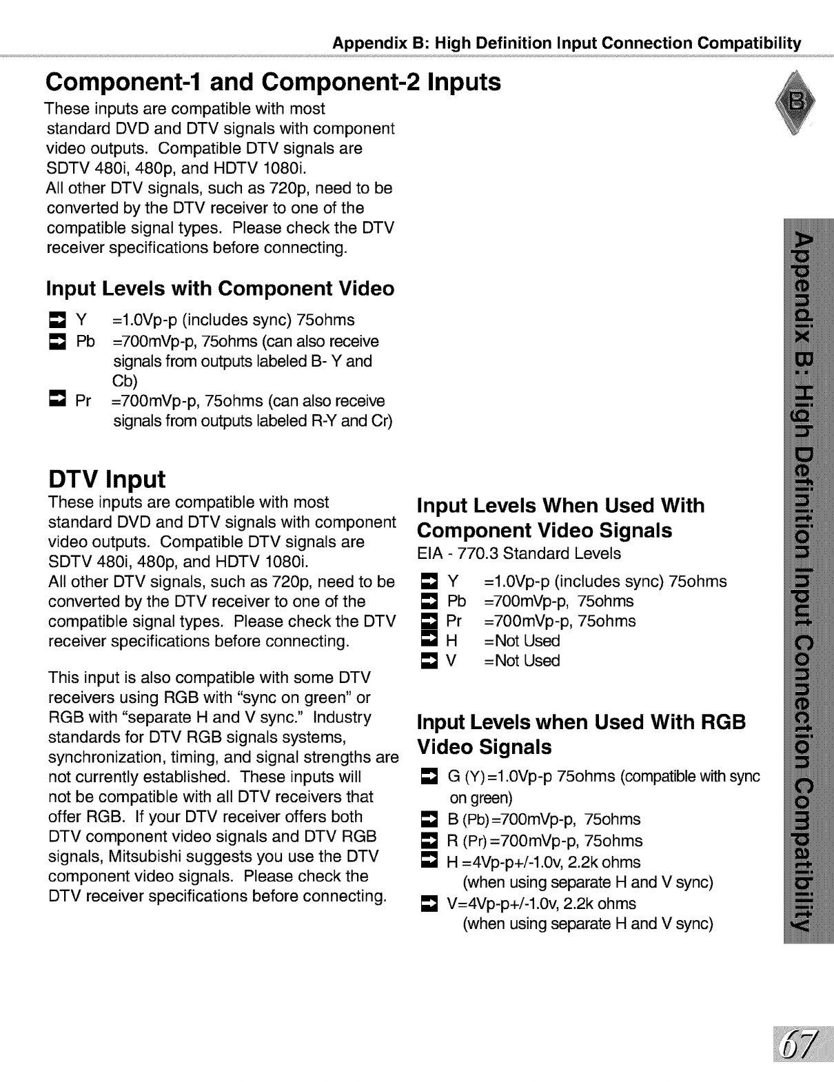
Appendix B: High Definition Input Connection Compatibility
Component-1 and Component-2 Inputs
These inputs are compatible with most
standard DVD and DTV signals with component
video outputs. Compatible DTV signals are
SDTV 480i, 480p, and HDTV 1080i.
All other DTV signals, such as 720p, need to be
converted by the DTV receiver to one of the
compatible signal types. Please check the DTV
receiver specifications before connecting.
Input Levels with Component Video
[]Y
Pb
L_J Pr
=l.0Vp-p (includes sync) 75ohms
=700mVp-p, 75ohms (can also receive
signals from outputs labeled B- Y and
Cb)
=700mVp-p, 75ohms (can also receive
signals from outputs labeled R-Y and Cr)
DTV Input
These inputs are compatible with most
standard DVD and DTV signals with component
video outputs. Compatible DTV signals are
SDTV 480i, 480p, and HDTV 1080i.
All other DTV signals, such as 720p, need to be
converted by the DTV receiver to one of the
compatible signal types. Please check the DTV
receiver specifications before connecting.
This input is also compatible with some DTV
receivers using RGB with "sync on green" or
RGB with "separate H and V sync." Industry
standards for DTV RGB signals systems,
synchronization, timing, and signal strengths are
not currently established. These inputs will
not be compatible with all DTV receivers that
offer RGB. If your DTV receiver offers both
DTV component video signals and DTV RGB
signals, Mitsubishi suggests you use the DTV
component video signals. Please check the
DTV receiver specifications before connecting.
Input Levels When Used With
Component Video Signals
EIA - 770.3 Standard Levels
_Y
E_J Pb
E_J Pr
[]H
_v
=l.0Vp-p (includes sync) 75ohms
=700mVp-p, 75ohms
=700mVp-p, 75ohms
=Not Used
=Not Used
Input Levels when Used With RGB
Video Signals
G (Y) =1.0Vp-p 75ohms (compatible with sync
on green)
B (Pb)=700mVp-p, 75ohms
R (Pr)=700mVp-p, 75ohms
H =4Vp-p+i-l.0v, 2.2k ohms
(when using separate H and V sync)
V=4Vp-p+i-l.0v, 2.2k ohms
(when using separate H and V sync)
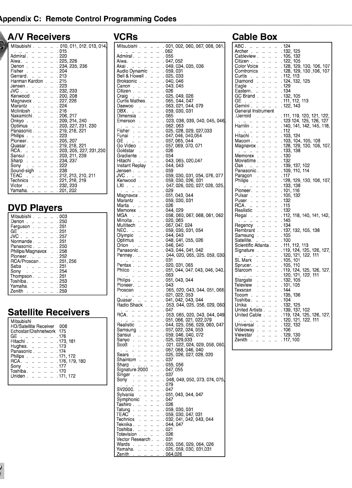
_.ppendix C: Remote Control Programming Codes
A/V Receivers
Mitsubishi ........ 010, 011,012,013, 014
.............. 015
Admiral .......... 220
Aiwa ............ 225, 226
Denon .......... 234, 235, 236
Fisher .......... 204
Gerrard .......... 213
Harman Kardon .... 215
Jensen .......... 223
JVC ............ 232, 233
Kenwood ........ 200, 208
Magnavox ........ 227, 228
Marantz ........ 224
Mclintosh ........ 216
Nakamichi ........ 206,217
Onkyo .......... 209, 214, 240
Optimus ........ 203, 227, 231,230
Panasonic ........ 219, 218,221
Philips .......... 223
Pioneer .......... 205, 207
Quasar .......... 219, 218,221
RCA ............ 203, 205, 227, 231,230
Sansui .......... 203, 211,239
Sharp .......... 234, 237
Sony .......... 222
Sound-sigh ...... 238
TEAC .......... 212,213, 210,211
Technics ........ 221,218, 219
Victor .......... 232, 233
Yamaha.......... 201,202
DVD Players
Mitsubishi ........ 003
Denon .......... 250
Ferguson ........ 251
GE ............ 251
JVC ............ 257
Normande ........ 251
Panasonic ........ 250
PhilipsiMagnavox .258
Pioneer .......... 252
ROAiProscan ...... 251,256
Saba .......... 251
Sony .......... 254
Thompson ........ 251
Toshiba .......... 253
Yamaha.......... 250
Zenith .......... 259
Satellite Receivers
Mitsubishi
HD/Satellite Receiver 006
Echostar/Dishnetwork 175
GE ............ 176
Hitachi .......... 173, 181
Hughes .......... 173
Panasonic ........ 174
Philips .......... 171,172
RCA ............ 176, 179, 180
Sony .......... 177
Toshiba .......... 170
Uniden .......... 171,172
VCRs
Mitsubishi ........ 001,002, 060,067, 068, 061,
.............. 062
Admiral .......... 055
Aiwa .........
Akai .........
Audio Dynamic ..
Bell & Howell. ..
Broksonic .....
Canon .......
Citizen .......
Craig ..
Curtis M'ati_es[ ..
Daewoo .....
DBX .........
.04_ 052
.049,034,035,036
.059,031
.025,033
.040,046
.043,045
.026
.025,049,026
• 065,044,047
.063,021,044,079
.059,030,031
Dimensia ...... 065
Emerson ........ 023, 038, 039, 040, 045, 046
.............. 062,063
Fisher ...... 025,028,029, 027,033
Funai . ..
GE .....
Go Video .
Goldstar
Gradiente .
Hitachi...
Instant Replay
densen .....
JVC .......
... 04_ 046,040,054
...05_ 065,044
.. .05_069,070,071
...026
...054
.. . 043,065,020,047
.. •044,043
...059
.. .059,030,031,054,076,077
Kenwood ...... 059,
LXI ............ 047,
.............. 029
Magnavox .... 051,
Marantz ... 059,
Marta ...... 026
Memorex .... 044,
MGA ...... 058,
Minolta ...... 020,
Multitech .... 067,
030,026,031
026,020,02_ 028,025,
043,044
030,031
029
060,06_ 068,061,062
O65
047,024
NEC ........ 059,030,031,054
Olympic ...044,043
Optimus ... 048,041,055,026
Orion ...... 046,040
Panasonic .... 043,044,041,042
Penney ...... 044, 020, 065,025, 059, 030
.............. 031
Pentax .......... 020,031,065
Philco .......... 051,044,04_ 043,046,040,
.............. 063
Philips .......... 051,043,044
Pioneer .......... 043
Proscan ........ 065,020,043,044,051,066
.............. 021,022,053
Quasar .......... 041,042, 043,044
Radio Shack ...... 053,044,025,056,029,060
.............. 047
RCA ............ 053,065,020,043,044,049
.............. 051,066,021,022,079
Realistic ........ 044,025,056,029,060,047
Samsung ........ 05_ 022,024,053
Sansui .......... 059,046,040,072
Sanyo .......... 025,029,033
Scott .......... 021,022,024,029,058,060
.............. 06_ 068,046,040
Sears .......... 025,026, 02_ 028,020
Shaintom ........ 037
Sharp .......... 055, 056
Signature 2000 .... 047, 055
Singer ...... 037
Sony .......... 048, 049, 050,073,074, 075,
.............. 079
SV2000 ........ 047
Sylvania .
Symphonic
Tashiro...
Tatung . ..
TEAC ..
Technics ..
Teknika .....
Toshiba .....
Totevision . ..
Vector Research ..
Wards .......
Yamaha.....
Zenith .....
043, 044,047
030,031
030,047,031
041,042,043,044
047
... 051,
...047
...026
...059,
.059,
• 032,
.044,
• 021
.026
• 031
.055,056,029,064,026
... 025,059, 030, 031,031
..... 064,026
Cable Box
ABC ............ 124
Archer .......... 132, 125
Cableview ........ 105, 132
Citizen .......... 122, 105
Color Voice ...... 128, 129, 130, 106, 107
Comtronics ...... 128, 129, 130,106, 107
Curtis .......... 112, 113
Diamond ........ 124, 132, 125
Eagle .......... 129
Eastern .......... 134
GO Brand ........ 132, 105
GE ............ 111,112, 113
Gemini .......... 122, 143
General Instrument
iJerrold ........ 111,119, 120, 121,122,
.............. 123 124, 125, 126, 127
Hamlin .......... 140, 141,142, 145, 118,
.............. 112
Hitachi .......... 103, 124
Macom .......... 103, 104, 105, 108
Magnavo× ........ 128, 129, 130, 106, 107,
.............. 133, 138
Memorex ........ 130
Movietime ........ 132
Oak ............ 139, 137, 102
Panasonic ........ 109, 110, 114
Paragon ........ 117
Philips .......... 128, 129, 130, 106, 107,
.............. 133, 138
Pioneer .......... 101,116
Pulsar .......... 105, 132
Puser .......... 132
RCA ............ 115
Realistic ........ 132
Regal .......... 112, 118, 140, 141,142,
.............. 145
Regency ........ 134
Rembrant ........ 137, 132, 105, 138
Samsung ........ 105
Satellite. .100
Scientific Atlanta .... 111,112, 113
Signature ........ 119, 124, 125, 126, 127,
.............. 120, 121,122, 111
SL Mark ........ 105, 101
Sprucer .......... 105, 110
Starcom ........ 119, 124, 125, 126, 127,
.............. 120, 121,122, 111
Stargate ........ 132, 105
Teleview ........ 101,105
Texscan ........ 144
Tocom .......... 135, 136
Toshiba .......... 104
Unika .......... 132, 125
United Artists ...... 139, 137, 102
United Cable ...... 119, 124, 125, 126, 127,
.............. 120, 121,122, 111
Universal ........ 122, 132
Videoway ........ 106
Viewstar ........ 129, 130
Zenith .......... 117,100
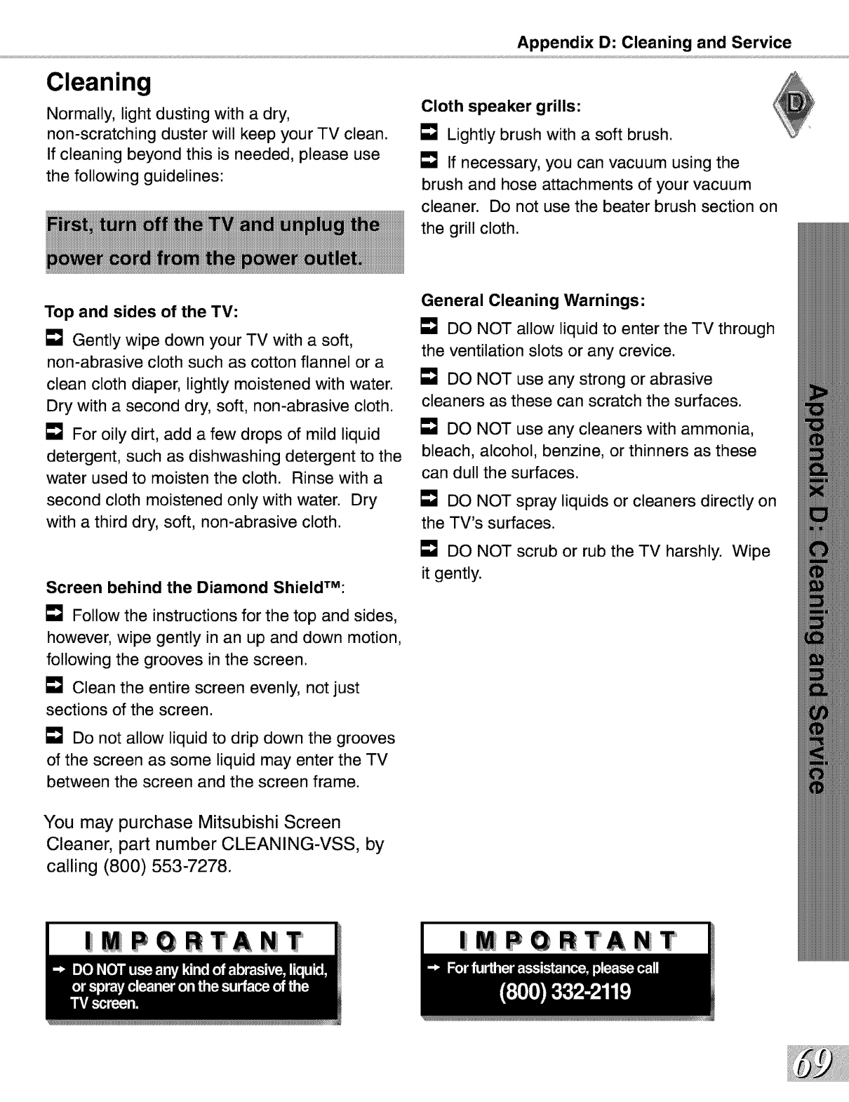
Appendix D: Cleaning and Service
Cleaning
Normally, light dusting with a dry,
non-scratching duster will keep your TV clean.
If cleaning beyond this is needed, please use
the following guidelines:
Cloth speaker grills:
[] Lightly brush with a soft brush.
E_J If necessary, you can vacuum using the
brush and hose attachments of your vacuum
cleaner. Do not use the beater brush section on
the grill cloth.
Top and sides of the TV:
Gently wipe down your TV with a soft,
non-abrasive cloth such as cotton flannel or a
clean cloth diaper, lightly moistened with water.
Dry with a second dry, soft, non-abrasive cloth.
For oily dirt, add a few drops of mild liquid
detergent, such as dishwashing detergent to the
water used to moisten the cloth. Rinse with a
second cloth moistened only with water. Dry
with a third dry, soft, non-abrasive cloth.
Screen behind the Diamond ShieldTM:
E_J Follow the instructions for the top and sides,
however, wipe gently in an up and down motion,
following the grooves in the screen.
Clean the entire screen evenly, not just
sections of the screen.
Do not allow liquid to drip down the grooves
of the screen as some liquid may enter the TV
between the screen and the screen frame.
General Cleaning Warnings:
DO NOT allow liquid to enter the TV through
the ventilation slots or any crevice.
DO NOT use any strong or abrasive
cleaners as these can scratch the surfaces.
E_J DO NOT use any cleaners with ammonia,
bleach, alcohol, benzine, or thinners as these
can dull the surfaces.
L"_ DO NOT spray liquids or cleaners directly on
the TV's surfaces.
DO NOT scrub or rub the TV harshly. Wipe
it gently.
You may purchase Mitsubishi Screen
Cleaner, part number CLEANING-VSS, by
calling (800) 553-7278.
|MPGRTANT |MPGRTANT
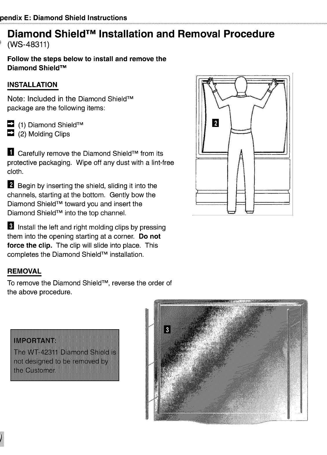
pendix E: Diamond Shield Instructions
Diamond Shield TM Installation and Removal Procedure
(WS-48311)
Follow the steps below to install and remove the
Diamond Shield TM
INSTALLATION
Note: Included in the Diamond Shield TM
package are the following items:
[] (1) Diamond Shield TM
[] (2) Molding Clips
[] Carefully remove the Diamond Shield TM from its
protective packaging. Wipe off any dust with a lint-free
cloth.
Begin by inserting the shield, sliding it into the
channels, starting at the bottom. Gently bow the
Diamond Shield TM toward you and insert the
Diamond Shield TM into the top channel.
[] Install the left and right molding clips by pressing
them into the opening starting at a corner. Do not
force the clip. The clip will slide into place. This
completes the Diamond Shield TM installation.
REMOVAL
To remove the Diamond Shield TM, reverse the order of
the above procedure.
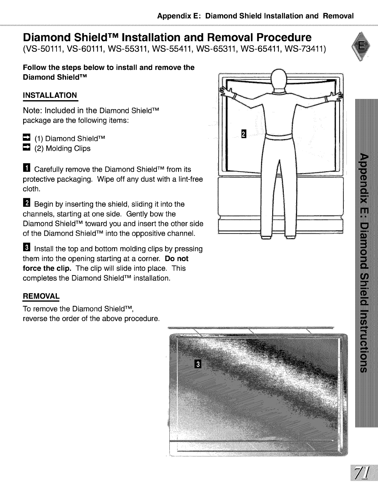
Appendix E: Diamond Shield Installation and Removal
Diamond Shield TM Installation and Removal Procedure
(VS-50111, VS-60111, WS-55311, WS-55411, WS-65311, WS-65411, WS-73411)
Follow the steps below to install and remove the
Diamond Shield TM
INSTALLATION
Note: Included in the Diamond Shield TM
package are the following items:
[] (1) Diamond Shield TM
[] (2) Molding Clips
[] Carefully remove the Diamond Shield TM from its
protective packaging. Wipe off any dust with a lint-free
cloth.
[] Begin by inserting the shield, sliding it into the
channels, starting at one side. Gently bow the
Diamond Shield TM toward you and insert the other side
of the Diamond Shield TM into the oppositive channel.
Install the top and bottom molding clips by pressing
them into the opening starting at a corner. Do not
force the clip. The clip will slide into place. This
completes the Diamond Shield TM installation.
REMOVAL
To remove the Diamond Shield TM,
reverse the order of the above procedure.
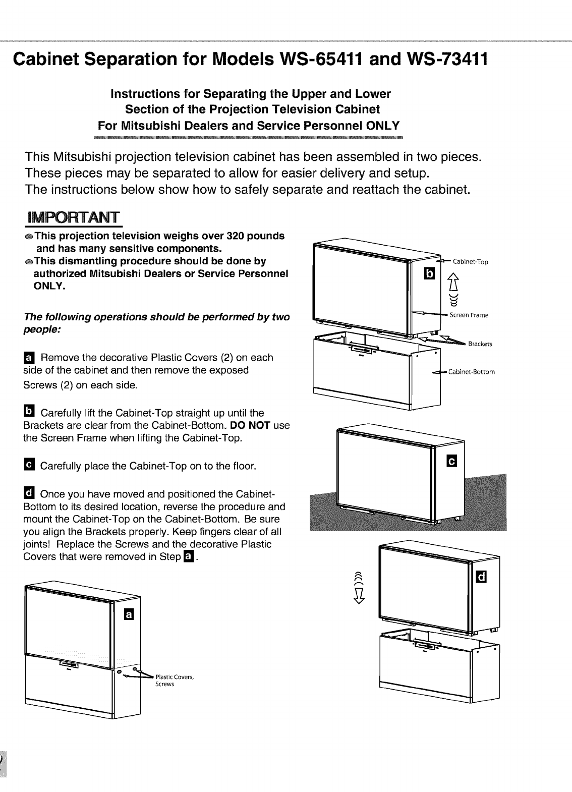
Cabinet Separation for Models WS-65411 and WS-73411
Instructions for Separating the Upper and Lower
Section of the Projection Television Cabinet
For Mitsubishi Dealers and Service Personnel ONLY
This Mitsubishi projection television cabinet has been assembled in two pieces.
These pieces may be separated to allow for easier delivery and setup.
The instructions below show how to safely separate and reattach the cabinet.
@This projection television weighs over 320 pounds
and has many sensitive components.
@This dismantling procedure should be done by
authorized Mitsubishi Dealers or Service Personnel
ONLY.
The following operations should be performed by two
people:
D Remove the decorative Plastic Covers (2) on each
side of the cabinet and then remove the exposed
Screws (2) on each side.
Carefully lift the Cabinet-Top straight up until the
Brackets are clear from the Cabinet-Bottom. DO NOT use
the Screen Frame when lifting the Cabinet-Top.
Carefully place the Cabinet-Top on to the floor.
Once you have moved and positioned the Cabinet-
Bottom to its desired location, reverse the procedure and
mount the Cabinet-Top on the Cabinet-Bottom. Be sure
you align the Brackets properly. Keep fingers clear of all
joints! Replace the Screws and the decorative Plastic
Covers that were removed in Step 1_
[]
Plastic Covers,
Screws
J
_!e binet-T°p
en Frame
_ Brackets
____ Cabinet-Bottom
B
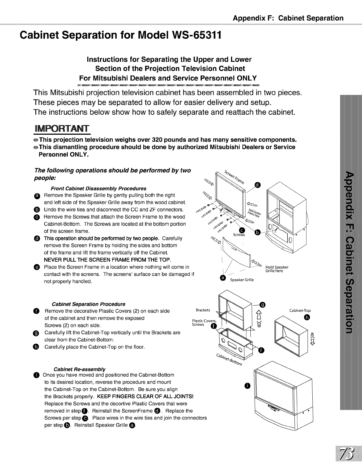
Appendix F: Cabinet Separation
Cabinet Separation for Model WS-65311
Instructions for Separating the Upper and Lower
Section of the Projection Television Cabinet
For Mitsubishi Dealers and Service Personnel ONLY
This Mitsubishi projection television cabinet has been assembled in two pieces.
These pieces may be separated to allow for easier delivery and setup.
The instructions below show how to safely separate and reattach the cabinet.
@This projection television weighs over 320 pounds and has many sensitive components.
_This dismantling procedure should be done by authorized Mitsubishi Dealers or Service
Personnel ONLY.
The following operations should be performed by two
people:
Front Cabinet Disassembly Procedures
O Remove the Speaker Grille by gently pulling both the right
and left side of the Speaker Grille away from the wood cabinet.
_]_ Undo the wire ties and disconnect the CC and ZF connectors.
Remove the Screws that attach the Screen Frame to the wood
Cabinet-Bottom. The Screws are located at the bottom portion
of the screen frame.
O This operation should be performed by two people. Carefully
remove the Screen Frame by holding the sides and bottom
of the frame and lift the frame vertically off the Cabinet.
NEVER PULL THE SCREEN FRAME FROM THE TOP.
O Place the Screen Frame in a location where nothing will come in
contact with the screens. The screens' surface can be damaged if
not properly handled.
J
f
Speaker Grille
Hold Speaker
Grille here
Cabinet Separation Procedure
Remove the decorative Plastic Covers (2) on each side
of the cabinet and then remove the exposed
Screws (2) on each side.
_) Carefully lift the Cabinet-Top vertically until the Brackets are
clear from the Cabinet-Bottom.
O Carefully place the Cabinet-Top on the floor.
Brackets
Plastic Covers,
Screws
Cabinet-Top
0Cabinet Re-assembly
Once you have moved and positioned the Cabinet-Bottom
to itsdesired location, reverse the procedure and mount
the Cabinet-Top on the Cabinet-Bottom. Be sure you align
the Brackets properly. KEEP FINGERS CLEAR OF ALL JOINTS!
Replace the Screws and the decortive Plastic Covers that were
removed in step_. Reinstall the ScreenFrame _]). Replace the
Screws per stepO. Place wires in the wire ties and join the connectors
per step _D. Reinstall Speaker Grille O.
O
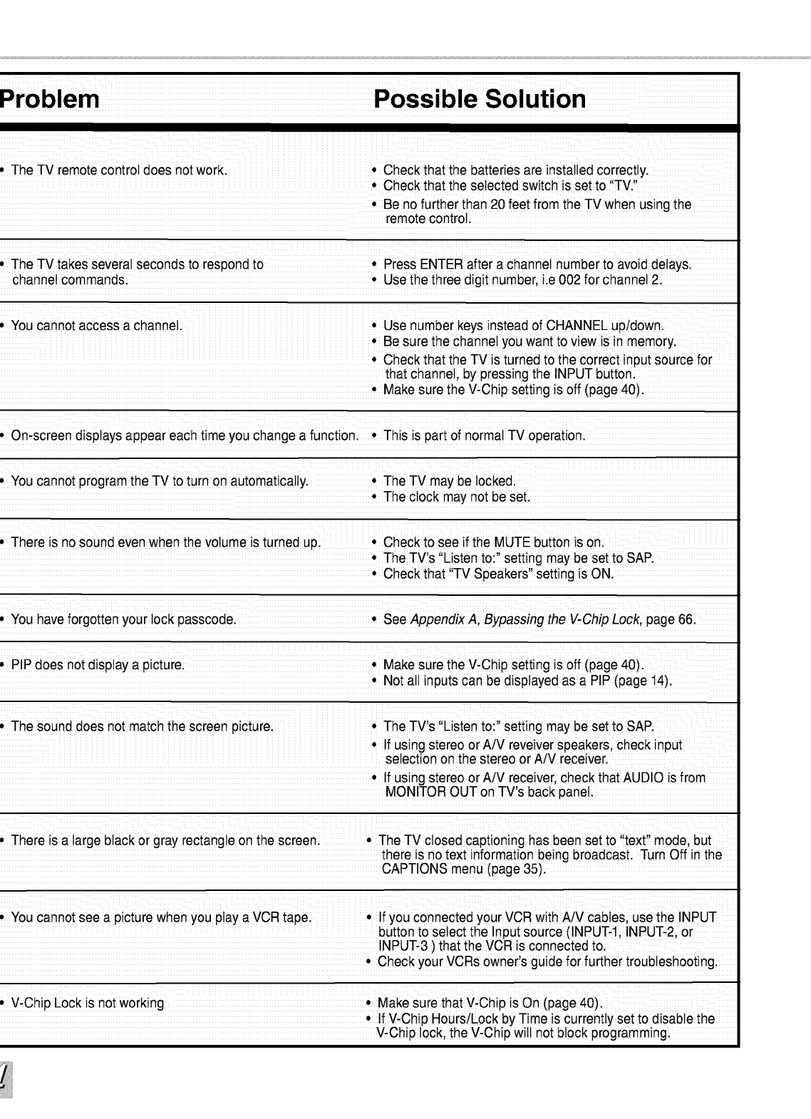
iiii iiii i _ i i ii
. The TV remote controi does not work:. Check that the batteries are installed correctly;
* Check that the selected switch is set to "TV
.Be no further than 20 feet from the TV when using the
remote control,
,The TV takes severat seconds to respond to. Press ENTER after a channel number to avoid delays
channel commands Use the three digit number lie 002 for channel 2
. You cannot access a channel: • Use number keys instead of CHANNEL up/down:
• Be sure the Channe!you want to view is in memory:
• Check that the TVis turned to the correct input source for
that channet by pressing the INPUT button:
Make sure the V,Chip setting is off (page 40):
.On-screen displays appear each time you change a functioni. This is part of normal TV operation
. You Cannotprogram the TV to turn on automaticaliy • The TV may be tockedi
• The clock may not be set
. There is nosound even when the volume is turned upl. Check to see if the MUTE button is on
• The TV's !'Listen to:,' setting may be set to SAR
Check that TV Speakers setting _sON
. You have forgotten your iock passcodel. See AppendixA, Bypassing the V ChipLockpage6&
. PIP does not disptay a picturei. Make sure the V-Chip setting is off (page 40):
Not a!!inputs Canbe displayed as a PiP (page 14)
. The sound does not match the screen picture: • The TV s ,!Listento!, setting may be set to SAP
• Ifusing stereo or A/V reveiver speakerscheck input
selection onthe stereo or A/V receiver.
If using stereo or A!V receiver, check that AUDIO is from
MONITOR OUT on TV,s back panet
.There is a iarge black or gray rectangie on thiescreen: i i !! .The TV closed captioning has been set to 'itext' model bui ii i
there is no text information!being broadcast; !Turn Off in tihe
CAPTIONSmenu(page35).
. You Cannotsee a picture when you play a VCR tape • If you connected your VCR with A!V cabies; use the INPUT
button to select the Input source (INPUT li INPUT 2, or
INPUT 3 ) that the VCR is connected tol
• Check your VCRs owner!s guide for further troubleshooting:
.V, Chip Lock is not working. Make sure that V-Chip is On (page 40):
•If V,Chip HourslLock by Time is currently set to disable the
V-Chip !ock, the V,Chip wi!! not b!ock programming
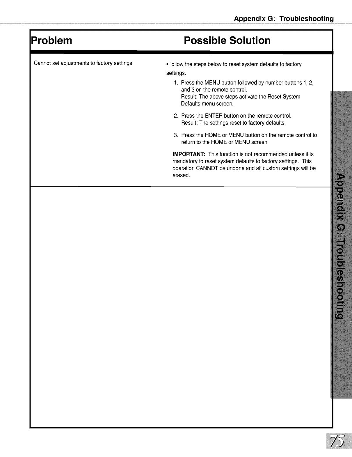
Appendix G: Troubleshooting
Problem Possible Solution
Cannot set adjustments to factory settings •Follow the steps below to reset system defaults to factory
settings.
1. Press the MENU button followed by number buttons 1, 2,
and 3 on the remote control.
Result: The above steps activate the Reset System
Defaults menu screen.
2. Pressthe ENTER button on the remote control.
Result: The settings resetto factory defaults.
3. Pressthe HOME or MENU button on the remote control to
return to the HOME or MENU screen.
IMPORTANT: This function is not recommended unless it is
mandatory to reset system defaults to factory settings. This
operation CANNOT be undone and all custom settings will be
erased.
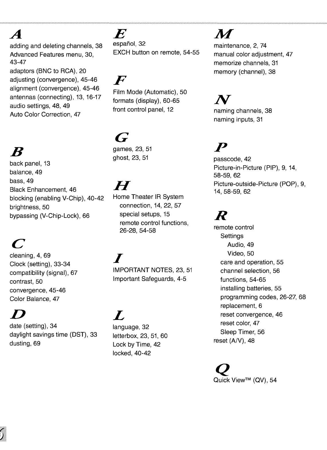
A
adding and deleting channels, 38
Advanced Features menu, 30,
43 -47
adaptors (BNC to RCA), 20
adjusting (convergence), 45-46
alignment (convergence), 45-46
antennas (connecting), 13, 16-17
audio settings, 48, 49
Auto Color Correction, 47
E
espafiol, 32
EXCH button on remote, 54-55
F
Film Mode (Automatic), 50
formats (display), 60-65
front control panel, 12
maintenance, 2, 74
manual color adjustment, 47
memorize channels, 31
memory (channel), 38
N
naming channels, 38
naming inputs, 31
B
back panel, 13
balance, 49
bass, 49
Black Enhancement, 46
blocking (enabling V-Chip), 40-42
brightness, 50
bypassing (V-Chip-Lock), 66
C
cleaning, 4, 69
Clock (setting), 33-34
compatibility (signal), 67
contrast, 50
convergence, 45-46
Color Balance, 47
date (setting), 34
daylight savings time (DST), 33
dusting, 69
G
games, 23, 51
ghost, 23, 51
H
Home Theater IR System
connection, 14, 22, 57
special setups, 15
remote control functions,
26-28, 54-58
I
IMPORTANT NOTES, 23, 51
Important Safeguards, 4-5
£
language, 32
letterbox, 23, 51, 60
Lock by Time, 42
locked, 40-42
F
passcode, 42
Picture-in-Picture (PIP), 9, 14,
58-59, 62
Picture-outside-Picture (POP), 9,
14, 58-59, 62
R
remote control
Settings
Audio, 49
Video, 50
care and operation, 55
channel selection, 56
functions, 54-65
installing batteries, 55
programming codes, 26-27, 68
replacement, 6
reset convergence, 46
reset color, 47
Sleep Timer, 56
reset (A/V), 48
Quick View TM (QV), 54
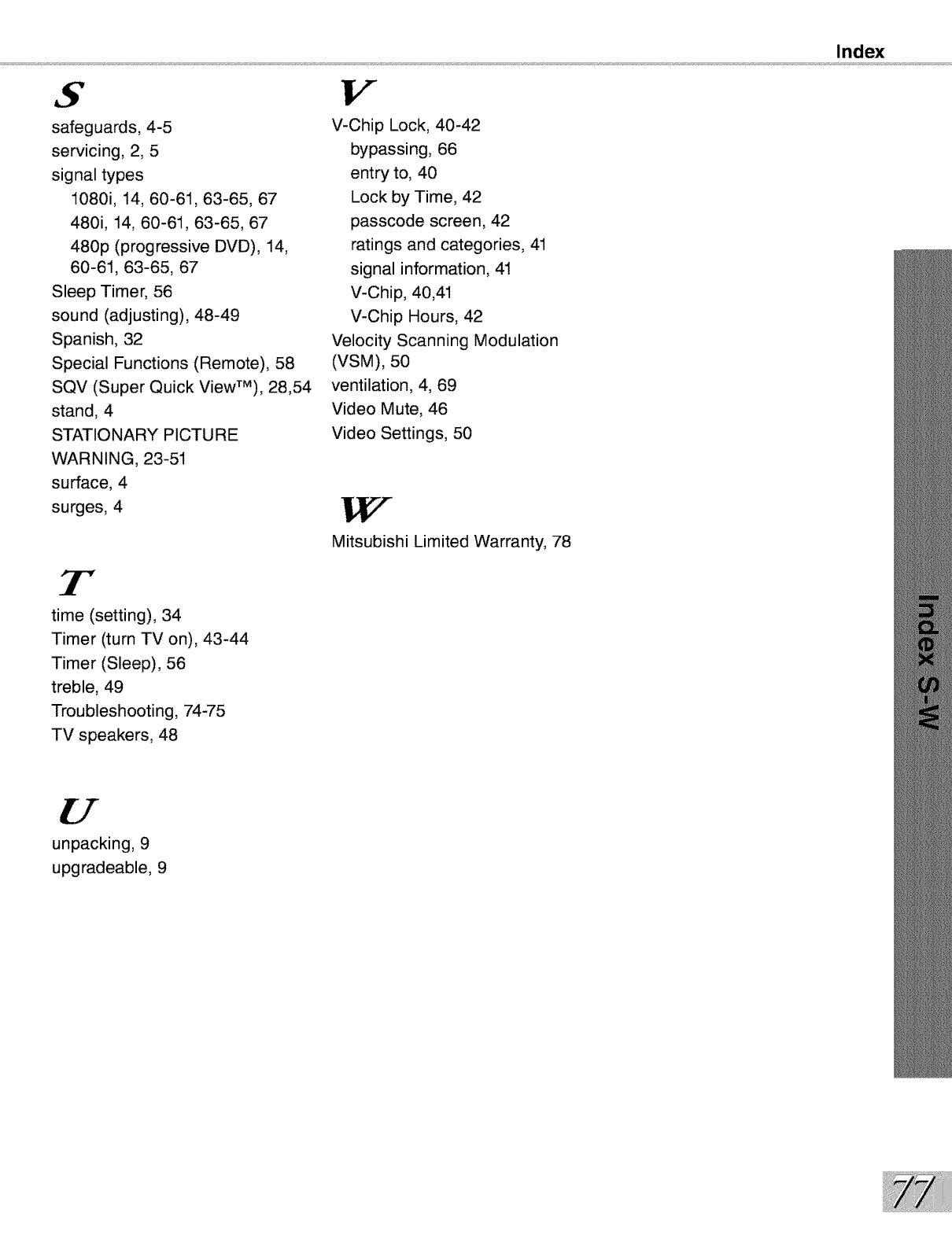
S
safeguards, 4-5
servicing, 2, 5
signal types
1080i, 14, 60-61, 63-65, 67
480i, 14, 60-61, 63-65, 67
480p (progressive DVD), 14,
60-61, 63-65, 67
Sleep Timer, 56
sound (adjusting), 48-49
Spanish, 32
Special Functions (Remote), 58
SQV (Super Quick ViewTM), 28,54
stand, 4
STATIONARY PICTURE
WARNING, 23-51
surface, 4
surges, 4
3r"
time (setting), 34
Timer (turn TV on), 43-44
Timer (Sleep), 56
treble, 49
Troubleshooting, 74-75
TV speakers, 48
V
V-Chip Lock, 40-42
bypassing, 66
entry to, 40
Lock by Time, 42
passcode screen, 42
ratings and categories, 41
signal information, 41
V-Chip, 40,41
V-Chip Hours, 42
Velocity Scanning Modulation
(VSM), 50
ventilation, 4, 69
Video Mute, 46
Video Settings, 50
Mitsubishi Limited Warranty, 78
Index
unpacking, 9
upgradeable, 9
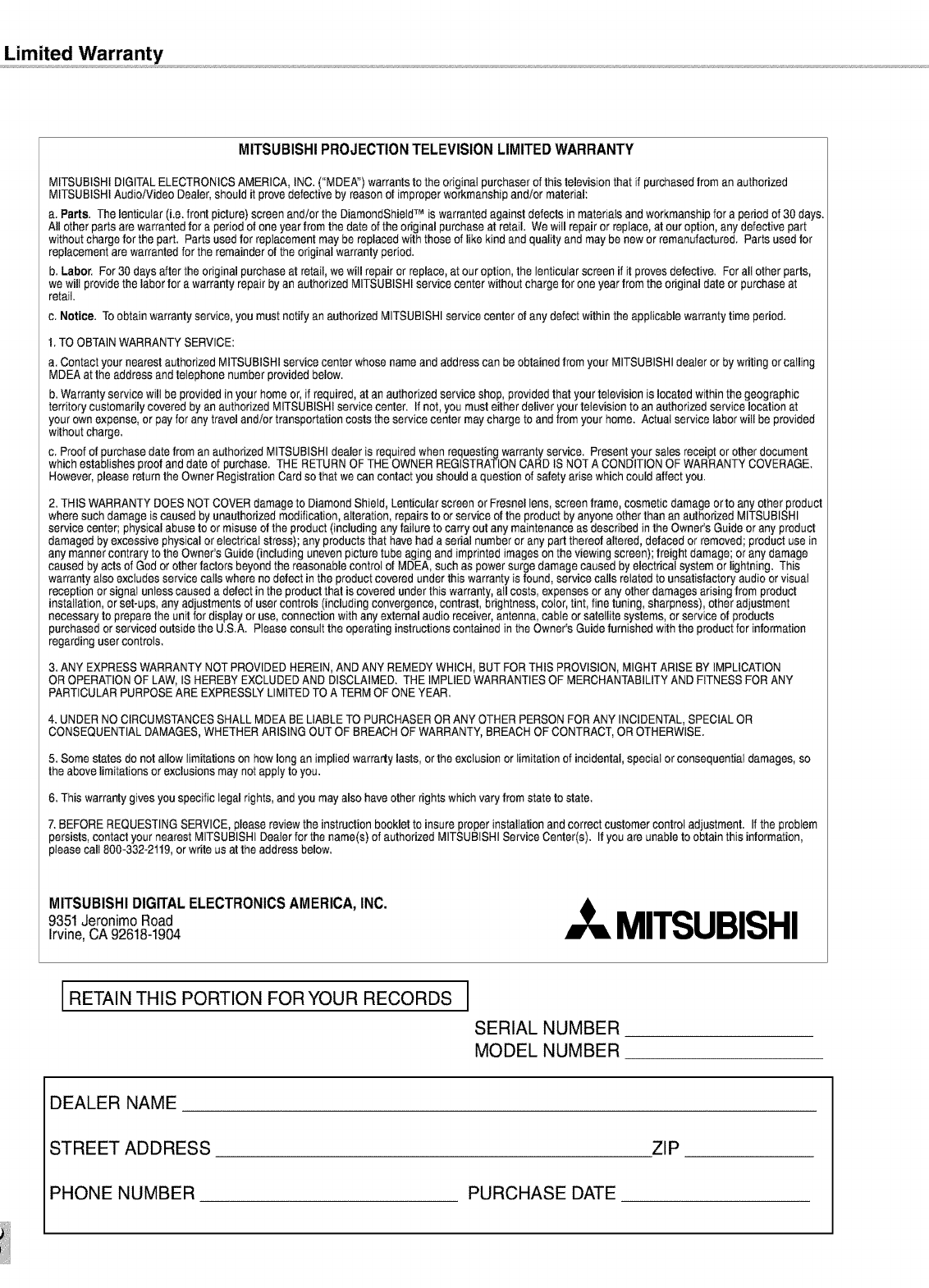
Limited Warranty
MITSUBISHIPROJECTIONTELEVISIONLIMITEDWARRANTY
MITSUBISHIDIGITALELECTRONICSAMERICA, INC.("MDEA") warrantsto the originalpurchaserof thistelevisionthat if purchasedfrom an authorized
MITSUBISHIAudio/Video Dealer,should it provedefective by reasonet improperworkmanshipand/or material:
a. Parts. Thelenticutar(i.e.front picture)screenand/or the DiamendShietdTM is warrantedagainst defectsin materialsand workmanshipfor a periodof 30 days.
All other parts are warrantedfor a periodot one yearfrom the date of the originalpurchaseat retail. Wewill repairor replace,at our option, anydefective part
withoutchargefor the part. Parts usedfor replacementmaybe replacedwith those of likekind and qualityand may be newor remanufactured. Parts usedfor
replacementare warrantedfor the remainderot the originalwarranty period.
b. Labor. For 30 days afterthe originalpurchaseat retail,we will repairor replace,at our option,the lenticularscreen if it provesdefective. Forall otherparts,
we will providethe labor fora warrantyrepair by an authorizedMITSUBISHIservicecenter withoutcharge forone yearfrom the originaldate or purchaseat
retail.
c. Notice. Toobtain warrantyservice, you mustnotify an authorizedMITSUBISHIservice center of any defectwithin the applicablewarranty timeperiod.
1. TO OBTAIN WARRANTY SERVICE:
a. Contactyour nearestauthorizedMITSUBISHIservicecenter whosenameand addresscan be obtainedfrom your MITSUBISHIdealeror by writingorcalling
MDEAat the addressand telephonenumber providedbelow.
b.Warrantyservice will be providedin your homeor, if required,at an authorizedserviceshop, providedthat your televisionis locatedwithin the geographic
territory customarilycoveredby an authorizedMITSUBISHIservicecenter. If net,you musteither deliveryourtelevision toan authorizedservice locationat
your own expense,or payfor anytraveland/ortransportationcosts the servicecentermaychargeto andfrom your home. Actual servicelaborwill be provided
withoutcharge.
c. Proof of purchasedate from an authorizedMITSUBISHIdealeris requiredwhen requestingwarranty service. Presentyour salesreceipt or otherdocument
which establishes proofand date of purchase. THE RETURNOF THEOWNERREGISTRATIONCARD IS NOTA CONDITIONOF WARRANTYCOVERAGE.
However,pleasereturnthe Owner RegistrationCardso that we can contact youshould a questionof safety arisewhich could affectyou.
2. THISWARRANTYDOES NOTCOVERdamageto Diamond Shield,Lenticularscreen orFreenellens, screenframe, cosmeticdamageotto anyother product
wheresuch damageis caused byunauthorizedmodification,alteration,repairsto orserviceof the productby anyoneother than an authorizedMITSUBISHI
servicecenter; physicalabuseto ormisuseofthe product(includinganyfailure to carry out anymaintenanceas describedinthe Owner's Guideor anyproduct
damagedbyexcessivephysicalor electricalstress); any productsthat havehada serial numberor anypartthereofaltered,defaced orremoved;productusein
any mannercontraryto the Owner'sGuide (including unevenpicturetube aging and imprinted imageson the viewingscreen);freightdamage;or anydamage
caused byacts of Godor otherfactors beyondthe reasonablecontrolel MDEA,suchaspowersurge damagecaused byelectrical systemor lightning. This
warranty also excludesservice calls whereno detect in the productcovered underthis warrantyis found, service calls relatedto unsatisfactoryaudioorvisual
receptionor signal unlesscauseda defect in the productthat is coveredunder this warranty,all costs,expensesor anyother damagesarisingfrom product
installation,orset-ups, anyadjustmentsof usercontrols (includingconvergence,contrast,brightness,color,tint, finetuning, sharpness),other adjustment
necessaryto preparethe unitfor displayor use,connectionwith any externalaudio receiver,antenna,cable orsatellitesystems, orserviceof products
purchasedor serviced outsidethe U.S.A. Pleaseconsultthe operatinginstructionscontainedinthe Owner'sGuidefurnishedwith the productfor information
regardinguser controls.
3. ANY EXPRESS WARRANTY NOT PROVIDED HEREIN, AND ANY REMEDY WHICH, BUT FOR THIS PROVISION, MIGHT ARISE BY IMPLICATION
OR OPERATION OF LAW, IS HEREBY EXCLUDED AND DISCLAIMED. THE IMPLIED WARRANTIES OF MERCHANTABILITY AND FITNESS FOR ANY
PARTICULAR PURPOSE ARE EXPRESSLY LIMITED TO A TERM OF ONE YEAR.
4. UNDER NO CIRCUMSTANCES SHALL MDEA BE LIABLE TO PURCHASER OR ANY OTHER PERSON FOR ANY INCIDENTAL, SPECIAL OR
CONSEQUENTIAL DAMAGES, WHETHER ARISING OUT OF BREACH OF WARRANTY, BREACH OF CONTRACT, OR OTHERWISE.
5. Somestates de not allow limitationson hew longan impliedwarrarly lasts,ortheexclusionorlimitationof incidental,special orconsequentialdamages,so
the abovelimitationsorexclusionsmay notapply to you.
6. Thiswarrantygives youspecificlegal rights,and you mayalso have otherrights whichvary from statetostate.
7. BEFOREREQUESTINGSERVICE,pleasereviewthe instructionbookletto insureproperinstallationand correctcustomercontrol adjustment. If the problem
persists,contactyour nearest MITSUBISHIDealerforthe name(s)of authorizedMITSUBISHIServiceCenter(s). If you are unableto obtainthis information,
pleasecall 800-332-2119,orwrite usat the address below.
MITSUBISHIDIGITALELECTRONICSAMERICA,INC.
9351JeronimoRoad
Irvine,CA92618-1904 MITSUBISHI
RETAIN THIS PORTION FORYOUR RECORDS I
SERIAL NUMBER
MODEL NUMBER
DEALER NAME
STREET ADDRESS ZIP
PHONE NUMBER PURCHASE DATE