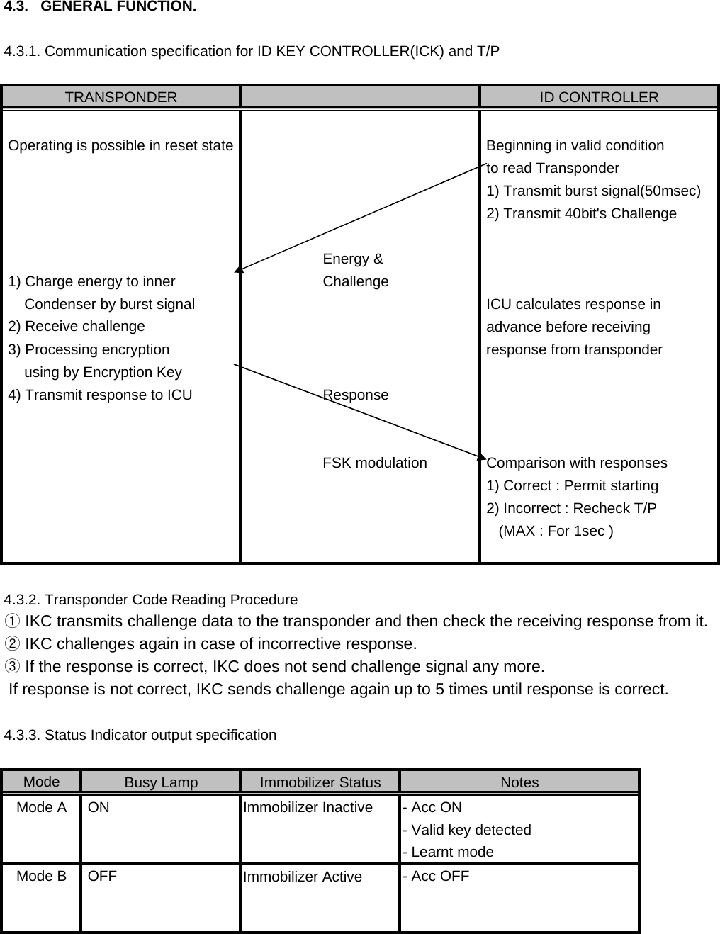
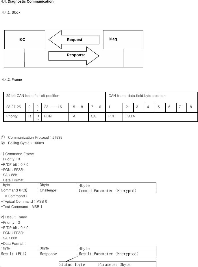
MOBASE ELECTRONICS SIS-PC200 CONTROLLER. ID KEY User Manual

Daedong Co. Ltd. CONTROLLER. ID KEY Users Manual

User manual

1/9           - Content -1. Coverage2. Overview3. System composition3.1. Transponser3.2. Coil Antenna3.3. Immobilizer ECU3.4. Engine ECU3.5. Diagnostic Tester3.6. Status Indicator4. General4.1. Electronic Performance    4.2. TRNSPONDER Communication Spec.4.3. GENERAL FUNCTION.4.4. Diagnostic Communication(주)신창전기
1. AbstractThis Specification is described an Anti-Theft System for automotive.2. OverviewThis Immobilizer System allows for an engine starting only if correct mechanical key as well as electronicalmatching by RF signal.3. System ConfigurationANSWER CODETRANSPONDERENERGY &CHALLENGESERIAL NUMBER와RESPONSECOIL ANT.SHLIMMOB.ECUDIAG.TESTERENGINEECUK-LINE REQUEST CODERELAY(주)신창전기
(주)신창전기
 3.1. TRANSPONDERAfter energyzing by RF signal from immobilizer, Transponderreceives challenge signals and then transmits response calculated by its own algorithm which is stored in ASIC. 3.2. COIL ANTENNALs (Inductance) : 447uH ± 20uH (IGN Lock barrel installation state)Rs (Resistance)     : ?Ω LowQ(Quality factor) : 25Low     Antenna coil works as a medium for RF communication between transponder and immobilizer. It is located      on the ignition lock barrel. 3.3. IMMOBILIZER ECU     It drives coil antenna and analyze data from transponder. And also it transmit answer code to ECU. 3.4. ENGINE ECU(ECM or EMS)     ECU analyzes the anwer data from immobilizer and then ECU decides to engine start or not  3.5. DIAGNOSTIC TESTER     It has diagnosis function, key teaching to immoblizer and entering user password.3.6. STATUS INDICATOR          It indicates the status of immbilizer such as lock or unlock.ASIC612CONDENSERCOIL(주)신창전기
4.3.   GENERAL FUNCTION.4.3.1. Communication specification for ID KEY CONTROLLER(ICK) and T/P            Energy &     ChallengeResponse      ModeMode A - Acc ON- Learnt modeMode B  OFF  - Acc OFFTRANSPONDER ID CONTROLLER Operating is possible in reset state  Beginning in valid condition to read Transponder 1) Transmit burst signal(50msec) 2) Transmit 40bit's Challenge 1) Charge energy to inner      Condenser by burst signal  ICU calculates response in  2) Receive challenge  advance before receiving  3) Processing encryption   response from transponder     using by Encryption Key 4) Transmit response to ICUFSK modulation  Comparison with responses 1) Correct : Permit starting 2) Incorrect : Recheck T/P- Valid key detected    (MAX : For 1sec )Busy Lamp Immobilizer Status NotesImmobilizer Active4.3.2. Transponder Code Reading Procedure① IKC transmits challenge data to the transponder and then check the receiving response from it.② IKC challenges again in case of incorrective response.③ If the response is correct, IKC does not send challenge signal any more. If response is not correct, IKC sends challenge again up to 5 times until response is correct.4.3.3. Status Indicator output specification ON Immobilizer Inactive
 4.4.2. Frame4.4. Diagnostic Communication 4.4.1. Block-SA : 88h①     Communication Protocol : J1939②     Polling Cycle : 100ms1) Command Frame-Priority : 3   ※Command :-Typical Command : MSB 0-Test Command : MSB 12) Result Frame-Priority : 3-R/DP bit : 0 / 0-PGN : FF32h-SA : 80h-Data Format :1byte 3byte 4byteResult (PCI)  Response Result Parameter (Encrypted)Status 1byte Parameter 3byte1byte 3byteCommand (PCI) Challenge Commad Parameter (Encryprd)4byte-R/DP bit : 0 / 0-PGN : FF33h-Data Format:IKC Diag.RequestResponse29 bit CAN Identifier bit position CAN frame data field byte position28 27 26 252423 …… 16 15 … 8 7 … 0Priority RDPPGN TA SA1PCI2DATA3 4 5 6 7 8
           "CAUTION: Exposure to Radio Frequency Radiation. Antenna shall be mounted in such a manner to minimize the potential for human contact during normal operation. The antenna should not be contacted during operation to avoid the possiblility of exceeding the FCC radio frequency exposure limit. The minimum separation distance of 20cm from the antenna to the body of user required."

Navigation menu