MOBASE ELECTRONICS SIS-PC200 CONTROLLER. ID KEY User Manual
Daedong Co. Ltd. CONTROLLER. ID KEY Users Manual
User manual

1/9
- Content -
1. Coverage
2. Overview
3. System composition
3.1. Transponser
3.2. Coil Antenna
3.3. Immobilizer ECU
3.4. Engine ECU
3.5. Diagnostic Tester
3.6. Status Indicator
4. General
4.1. Electronic Performance
4.2. TRNSPONDER Communication Spec.
4.3. GENERAL FUNCTION.
4.4. Diagnostic Communication
(주)신창전기

1. Abstract
This Specification is described an Anti-Theft System for automotive.
2. Overview
This Immobilizer System allows for an engine starting only if correct mechanical key as well as electronical
matching by RF signal.
3. System Configuration
ANSWER CODE
TRANSPONDER
ENERGY &
CHALLENGE
SERIAL NUMBER와
RESPONSE
COIL ANT.
SHL
IMMOB.ECU
DIAG.
TESTER
ENGINE
ECU
K-LINE REQUEST CODE
RELAY
(주)신창전기
(주)신창전기
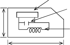
3.1. TRANSPONDER
After energyzing by RF signal from immobilizer, Transponder
receives challenge signals and then transmits response
calculated by its own algorithm which is stored in ASIC.
3.2. COIL ANTENNA
Ls (Inductance) : 447uH ± 20uH (IGN Lock barrel installation state)
Rs (Resistance) : ?Ω Low
Q(Quality factor) : 25Low
Antenna coil works as a medium for RF communication between transponder and immobilizer. It is located
on the ignition lock barrel.
3.3. IMMOBILIZER ECU
It drives coil antenna and analyze data from transponder. And also it transmit answer code to ECU.
3.4. ENGINE ECU(ECM or EMS)
ECU analyzes the anwer data from immobilizer and then ECU decides to engine start or not
3.5. DIAGNOSTIC TESTER
It has diagnosis function, key teaching to immoblizer and entering user password.
3.6. STATUS INDICATOR
It indicates the status of immbilizer such as lock or unlock.
ASIC
6
12
CONDENSER
COIL
(주)신창전기
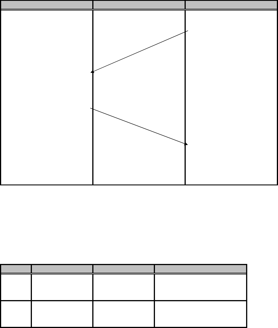
4.3. GENERAL FUNCTION.
4.3.1. Communication specification for ID KEY CONTROLLER(ICK) and T/P
Energy &
Challenge
Response
Mode
Mode A - Acc ON
- Learnt mode
Mode B OFF - Acc OFF
TRANSPONDER ID CONTROLLER
Operating is possible in reset state Beginning in valid condition
to read Transponder
1) Transmit burst signal(50msec)
2) Transmit 40bit's Challenge
1) Charge energy to inner
Condenser by burst signal ICU calculates response in
2) Receive challenge advance before receiving
3) Processing encryption response from transponder
using by Encryption Key
4) Transmit response to ICU
FSK modulation Comparison with responses
1) Correct : Permit starting
2) Incorrect : Recheck T/P
- Valid key detected
(MAX : For 1sec )
Busy Lamp Immobilizer Status Notes
Immobilizer Active
4.3.2. Transponder Code Reading Procedure
① IKC transmits challenge data to the transponder and then check the receiving response from it.
② IKC challenges again in case of incorrective response.
③ If the response is correct, IKC does not send challenge signal any more.
If response is not correct, IKC sends challenge again up to 5 times until response is correct.
4.3.3. Status Indicator output specification
ON Immobilizer Inactive
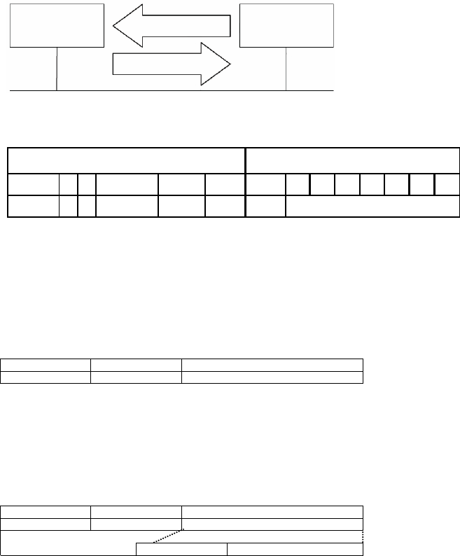
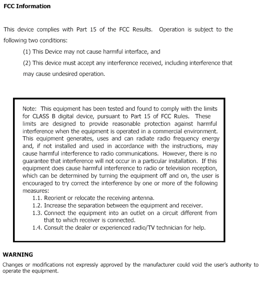
4.4.2. Frame
4.4. Diagnostic Communication
4.4.1. Block
-SA : 88h
① Communication Protocol : J1939
② Polling Cycle : 100ms
1) Command Frame
-Priority : 3
※Command :
-Typical Command : MSB 0
-Test Command : MSB 1
2) Result Frame
-Priority : 3
-R/DP bit : 0 / 0
-PGN : FF32h
-SA : 80h
-Data Format :
1byte 3byte 4byte
Result (PCI) Response Result Parameter (Encrypted)
Status 1byte Parameter 3byte
1byte 3byte
Command (PCI) Challenge Commad Parameter (Encryprd)
4byte
-R/DP bit : 0 / 0
-PGN : FF33h
-Data Format:
IKC Diag.
Request
Response
29 bit CAN Identifier bit position CAN frame data field byte position
28 27 26 2
5
2
4
23 …… 16 15 … 8 7 … 0
Priority R
D
P
PGN TA SA
1
PCI
2
DATA
3 4 5 6 7 8
"CAUTION: Exposure to Radio Frequency Radiation.
Antenna shall be mounted in such a manner to minimize the potential for human
contact during normal operation. The antenna should not be contacted during
operation to avoid the possiblility of exceeding the FCC radio frequency exposure
limit. The minimum separation distance of 20cm from the antenna to the body of
user required."