MOELCA S R L 1504 AUTOMATIC EXTRACTOR OF EMOCOMPONENTS User Manual Rev 1 05
MOELCA S.R.L. AUTOMATIC EXTRACTOR OF EMOCOMPONENTS Rev 1 05
User Manual

ARCHIMEDE
User Manual
Revision 1.05

Page 2 of 105 User Manual Revision 1.05
MOELCA s.r.l.
Registered Office: Via E.Toti 101
Offices: Via del Lavoro 19
22070 Limido Comasco (CO)
031-3520153 3520279 3524739
Fax 031-3524732
E-mail info@moelca.it
Manufacturer Responsibility
The instructions for use may contain a declaration that the Manufacturer, the Assembler, the
Installer or the Importer consider themselves responsible for instrument safety, reliability and
performance only if:
• assembling, extensions, adjustments, changes or repairs are performed by qualified
service personnel under his authorization;
• the instrument is operated in a room whose electrical system applies with the relevant
prescriptions;
• the instrument is operated according to the instructions for use.
The device complies with part 15 of the FCC Rules. Operation is subjected to the following 2
conditions: (1) this device may not cause harmful interference and (2) this device must accept
any interference received, including interference that may cause undesired operation”
Changes or modifications not expressly approved by the party responsible for compliance could
void the user's authority to operate the equipment.
COPYRIGHT
All rights reserved. The contents of this document may not be reproduced, stored in a retrieval
system, transmitted in any form or electronic mean, used for different aims without the prior
written consent of MOELCA s.r.l.
This document is subject to change without notice.
While the utmost care has been taken for collection and verification of the documentation
contained in the present manual, MOELCA s.r.l. assumes no responsibility deriving from the
use of the same. MOELCA s.r.l. assumes no responsibility for people or companies involved in
the creation and issuing of the present manual.

User Manual Revision 1.05 Page 3 of 105
WARRANTY
MOELCA s.r.l. certifies that the instrument is free from any defect when shipped from factory.
The warranty covers the instrument and all its parts for a period of 12 months from delivery
date.
During the warranty period MOELCA s.r.l. will repair or replace free of charge (at its discretion
and ex factory) the parts or units that prove to be defective. All parts or units replaced will
become MOELCA s.r.l. property. The warranty is automatically voided in case of violations,
changes, different use from that described in the instructions, wrong plugging in power mains,
repairs performed by personnel not authorized by MOELCA s.r.l., accidental breakings due to
transportation or falls, lack or deletion or modification of the serial number.
In case of repairs not covered by the warranty, MOELCA s.r.l. or its representatives will draw
up a quotation and provide for repair upon written acceptance of the customer.
Service
During the warranty period the instrument should not be modified or repaired by personnel
not authorized by MOELCA S.r.l. For information about service please contact:
Any repair after the warranty period should be performed by qualified personnel properly
instructed by MOELCA s.r.l.

Page 4 of 105 User Manual Revision 1.05
Revisions Log
Manual
Revision # Software
Revision # Date Author Changes
1.00 1.00 01/03/2006 C. Milani Original Document
1.01 1.08 21/07/2007 C. Milani
Change in separation
procedures and WLAN.
1.02 1.12 03/03/2008 C. Milani Modify like Fenwal suggestion.
1.03 2.00 06/06/2008 C. Milani FCC ID rules-IP41
1.04 2.20 24/06/2008 C. Milani Modify as PRS reference
1.05 2.25 10/01/2009 C. Milani Change in troubleshooting.
SYMBOLS
User Manual Revision 1.05 Page 5 of 105
The following list contains symbols and marks used in this manual.
Class I In this instrument the protection against direct and indirect contacts does not
consist only of the basic insulation but, also of an additional safety measure.
Instrument with applied part type B.
SN Symbol for “SERIAL NUMBER”.
Caution: please read attached documentation.
Caution: keep hands off this area.
Not ionized radiation.
Discard separately.
Manufacturer.
CE mark certifying compliance with MDD 93/42 guideline.

CONTENTS
Page 6 of 105 User Manual Revision 1.05
WARRANTY 3
1 INTRODUCTION 11
1.1 Intended Use.............................................................................. 11
1.2 Key features............................................................................... 11
2 INSTALLATION 13
2.1 Unpacking Archimede .................................................................. 13
2.2 Positioning Archimede.................................................................. 13
2.3 Assembling scale, filter holders and antenna. .................................. 13
2.4 Switching on Archimede ............................................................... 14
2.5 Instrument Setup........................................................................ 15
2.5.1 Date and Time 15
2.5.2 Procedures Setup Check 16
3 GENERAL DESCRIPTION 17
3.1 Upper Panel ............................................................................... 17
3.2 Front Panel ................................................................................ 17
3.2.1 Keyboard 18
3.2.2 Backlight Display 19
3.3 Rear Panel ................................................................................. 20
3.4 Side Panel.................................................................................. 20
3.5 Meaning of Procedure Parameters.................................................. 21
3.6 Procedure Parameters Display....................................................... 24
3.7 Maintenance Display.................................................................... 24
3.8 Date and Time............................................................................ 24
3.9 Scales ....................................................................................... 25
3.10 Manual Control of Plate Forward Moving ......................................... 25
3.11 Clamps Manual Control ................................................................ 26
4 USING ARCHIMEDE 27
4.1 Switching on .............................................................................. 27
4.2 System Self-check....................................................................... 27
4.3 Use as a scale............................................................................. 30
4.4 Use as a sealing unit.................................................................... 30
4.5 Use as manual separator.............................................................. 31
4.6 Separation Procedure .................................................................. 32
4.6.1 Questions 33
4.6.2 PROCEDURE 1 T & T triple PPP or PRP + RCC. 34
4.6.3 PROCEDURE 2 T & T quadruple PPP or PRP BC + RCC. 39
4.6.4 PROCEDURE 3 Top & Bottom triple PPP+BC+RCC. 44
4.6.5 PROCEDURE 4 Top & Bottom quadruple PPP+BC+RCC. 49
4.6.6 PROCEDURE 5 Separation from PRP to PPP+PLT 54
4.6.7 PROCEDURE 7 Single or Pool of Buffy for PLT + residual BC with filter 59
4.6.8 PROCEDURE 8 Separation of Erythrocytes Washing 64
4.6.9 PROCEDURE 10 [a]UMBILICAL CORD 69
4.6.10 PROCEDURE 11 [b] ALIQUOTE SEPARATION 74
4.6.11 PROCEDURE 13 [d] T & T for RCC diluted in Plasma + Predefined HCT. 79
5 SCALE CALIBRATION 85
6 DATA TRANSFER 87
6.1 WLAN ........................................................................................ 87
6.2 Firmware Update and Procedures Protocols ..................................... 87
6.3 Data transmission and reception ................................................... 88
6.3.1 Example of procedure data transmission: 90
6.3.2 List of symbols used in the transmission protocol: 90
7 TROUBLESHOOTING 91

CONTENTS
User Manual Revision 1.05 Page 7 of 105
7.1 Errors and Possible Solutions ........................................................ 91
7.2 Errors with Archimede codes......................................................... 91
8 Maintenance 99
8.1 Daily Maintenance ....................................................................... 99
8.1.1 Cleaning 99
8.1.2 Decontamination 99
8.1.3 Monthly Maintenance 99
8.2 Yearly Maintenance ..................................................................... 99
8.3 Maintenance Recording ................................................................ 99
9 ACCESSORIES 101
10 DISPOSAL 103
10.1 Packing Material Disposal ........................................................... 103
10.2 Archimede Disposal ................................................................... 103
11 TECHNICAL FEATURES 105
PICTURES
Picture 1: Parts included in the packing. 13
Picture 2: Archimede display 14
Picture 3: Screen shot “Self Test” 14
Picture 4: Date and time menu. 15
Picture 5: Date and time format list. 15
Picture 6: Utility menu. 16
Picture 7: Parameters procedures list 16
Picture 8: Global view 17
Picture 9: Keyboard 18
Picture 10: Main menu 19
Picture 11: Lateral view 20
Picture 12: Utility menu. 24
Picture 13: Parameters procedures list 24
Picture 14: Maintenance list 24
Picture 15: Date and time menu. 25
Picture 16: Date and time format list. 25
Picture 17: Screen shot “Self-Test in progress” 27
Picture 18: Scale tare 30
Picture 19: Reading scale area 30
Picture 20: Archimede view 30
Picture 21: Manual movement window 31
Picture 22: Enable procedures list 32
Picture 23: Questions view 33
Picture 24: Kit installation procedure T/T triple 35
Picture 25: Position primary T/T triple bag. 35
Picture 26: Position plasma and Sag.M. T/T triple bags. 35
Picture 27: T/T Triple bags in position. 36
Picture 28: Break cannulas view T/T triple procedure. 36
Picture 29: Sealing procedure T/T triple 37
Picture 30: Viewing weights T / T triple. 37
Picture 31: Reweigh T/T quadruple. 37
Picture 32: T/T quadruple with weight out of normal range. 38
Picture 33: Pause or Stop procedure T/T triple. 38
Picture 34: Kit installation T/T quadruple procedure. 40
Picture 35: Position primary T/T triple bag. 40
Picture 36: Position plasma, buffy coat and Sag.M. T/T quadruple bags. 40
Picture 37: T/T quadruple bags in position 41
Picture 38: Break cannulas view quadruple T/T procedure 41
Picture 39: Sealing procedure T/T quadrupla 42

CONTENTS
Page 8 of 105 User Manual Revision 1.05
Picture 40: Viewing weights T / T quadruple. 42
Picture 41: T/T quadruple with weight out of normal range. 42
Picture 42: T/T quadruple with weight out of normal range 43
Picture 43: Pause or Stop procedure T/T quadruple 43
Picture 44: Kit installation T/B triple procedure. 45
Picture 45: Position primary T/B triple bag. 45
Picture 46: Position plasma, buffy coat and Sag.M. T/T triple bags. 45
Picture 47: T/B triple bags in position. 46
Picture 48: Break cannulas view T/B triple procedure. 46
Picture 49: Sealing procedure T/B tripe 47
Picture 50: Viewing weights T / B triple. 47
Picture 51: Reweigh T/B triple 47
Picture 52: T/B triple with weight out of normal range. 48
Picture 53: Pause or Stop procedure T/B triple 48
Picture 54: Kit installation T/B quadruple procedure 50
Picture 55: Position primary T/B quadrupla bag. 50
Picture 56: Position plasma, buffy coat and Sag.M. T/B quadruple bags. 50
Picture 57: T/B quadruple bags in position. 51
Picture 58: Break cannulas view T/B quadruple procedure. 51
Picture 59: Sealing Procedure T/B quadruple 52
Picture 60: Viewing weight T/B quadruple 52
Picture 61: Reweight T/B quadruple 53
Picture 62: T/B quadruple with weight out of normal range. 53
Picture 63: Pause or Stop procedure T/B quadruple. 53
Picture 64: Kit installation procedure PRP to PPP+PLT 55
Picture 65: Position primary bag procedure PRP to PPP + PRP 55
Picture 66: Position PLT bag procedure PRP to PPP + PRP. 55
Picture 67: PRP to PPP + PRP bags in position. 56
Picture 68: Break cannulas view procedure PRP to PPP + PRP 56
Picture 69: Sealing procedure PRP to PPP + PRP 57
Picture 70: Viewing weight PRP to PPP + PRP. 57
Picture 71: Reweight procedure PRP to PPP + PRP. 57
Picture 72: Procedure PRP to PPP + PRP with weight out of normal range.. 58
Picture 73: Pause or Stop procedure PRP to PPP + PRP. 58
Picture 74: Kit installation procedure PLT with filter 60
Picture 75: Position primary bag separation PLT with filter. 60
Picture 76: Position PLT bag separation PLT with filter. 60
Picture 77: Bag PLT with filter in position. 61
Picture 78: Break cannulas view procedure PLT with filter. 61
Picture 79: Sealing procedure PLT with filter. 62
Picture 80: Viewing weight PLT with filter. 62
Picture 81: Reweight procedure PLT with filter. 62
Picture 82: Procedure PLT with filter with weight out of normal range. 63
Picture 83: Pause or Stop procedure PLT with filter. 63
Picture 84: Kit installation procedure erythrocytes washing. 65
Picture 85: Position primary bag erythrocytes washing. 65
Picture 86: Position erythrocytes washing bag. 65
Picture 87: Erythrocytes washing bag in position. 66
Picture 88: Break cannulas view erythrocytes washing procedure 66
Picture 89: Sealing erythrocytes washing procedure. 67
Picture 90: Viewing weight erythrocytes washing . 67
Picture 91: Reweight procedure erythrocytes washing. 67
Picture 92: Pause or Stop in procedure erythrocytes washing . 68
Picture 93: Kit installation procedure umbilical cord 70
Picture 94: Position primary bag umbilical cord procedure. 70
Picture 95: Position plasma, RBC bag of umbilical cord procedure. 70
Picture 96: Erythrocytes umbilical cord in position. 71
Picture 97: Break cannulas view umbilical cord procedure. 71
Picture 98: Sealing umbilical cord procedure. 72

CONTENTS
User Manual Revision 1.05 Page 9 of 105
Picture 99: Viewing weight umbilical cord procedure 72
Picture 100: Reweight umbilical cord procedure. 72
Picture 101: Pause or Stop procedure umbilical cord. 73
Picture 102: Kit installation aliquot separation procedure. 75
Picture 103: Position primary bag aliquot separation procedure. 75
Picture 104: Position aliquot separation procedure. bag. 75
Picture 105: Aliquot separation procedure bag in position. 76
Picture 106: Break cannulas view aliquot separation procedure. 76
Picture 107: Viewing weight aliquot separation procedure. 77
Picture 108: Reweight aliquot separation procedure. 77
Picture 109: Saldatura procedura separazione in aliquote 77
Picture 110: Pause or Stop aliquot separation. 78
Picture 111: Kit installation procedure T & T with predefined HCT. 80
Picture 112: Position primary bag T & T with predefined HCT procedure. 80
Picture 113: Position plasma bag T & T with predefined HCT procedure. 80
Picture 114: T & T with predefined HCT procedure bag in position. 81
Picture 115: Break cannulas view procedure T & T with predefined HCT. 81
Picture 116: Sealing procedure RCC T & T with predefined HCT. 82
Picture 117: Viewing RCC T & T with predefined HCT procedure. 82
Picture 118: Reweight T & T with predefined HCT procedure. 82
Picture 119: RCC T & T with predefined HCT procedure with weight out of normal range. 83
Picture 120: Pause or Stop procedure RCC T & T with predefined HCT. 83
Picture 121: Calibration menu. 85
Picture 122: Calibration, weight sample setting. 85
Picture 123: First step calibration. 85
Picture 124: Second step calibration. 85
Picture 125: Calibrazione, visualizzazione fattori di correzione. 86
Picture 126: WLAN connection 87
Picture 127: Communication request from Archimede 88
Picture 128: Communication request from ArchimedeLINK 89
Picture 129: Maintenance view 99

CONTENTS
Page 10 of 105 User Manual Revision 1.05

INTRODUCTION
User Manual Revision 1.05 Page 11 of 105
1 INTRODUCTION
The present user manual describes functions, operation and using instructions of Archimede.
Please read the present document before using the instrument, and keep it to hand for
consultation in order to ensure proper system operation.
Archimede is an automatic extractor of emocomponents from whole blood. It allows to
separate Erythrocytes, Buffy Coat, and Platelets from rich and poor plasma and platelet
concentrate.
Both Standard and Top & Bottom bags can be used and, thanks to the high automatization one
single operator can use several units at the same time. The laboratory productivity is therefore
increased maintaining a high and standardized separation quality.
The separation procedure is continuously checked by a dedicated microcontroller. In case of
alarm or if the preset parameter values are reached, the procedure is stopped.
1.1 Intended Use
Archimede should be used by Qualified Personnel only. It has been designed for the separation
of emocomponents contained in hermetically sealed bags (bags containing whole blood and/or
blood derivatives) consistent with the International Standard ISO 3826 and with the 93/42
MDD regulation. For optimum operation Archimede should be placed on a solid and stable
surface, preferably away from direct heat sources.
1.2 Key features
• User-friendly interface.
• Graphic display of bags weight, force, and operation stages.
• Automatic delivery of Sag. M. through press.
• Variable speed separation movement, controlled by a stepper motor.
• Array of ten optical sensors for Buffy Coat level check.
• Optical detector of RBC, with electronic control of cover closure.
• Electronic control of the distance between plate and profile plate.
• Electronic control of the applied force with motor stop in case the safety limit is
exceeded.
• Three scales with 2 Kg full-scale and 1 g resolution.
• Six clamps: four sealing-head clamps, one flow control clamp, one normal clamp.
• Mechanical buffy-coat separation system.
• Detection system of proper tubes positioning in each clamp.
• Can store up to 18 separation procedures, with approx. 40 parameters each.
• Self-tare and auto-calibration of the various measuring systems via software.
Regulation trimmers have therefore been eliminated. The auto-calibration functions
are managed directly by ArchimedeLINK.
• Can be used as a sealer and as a scale .
• Self-diagnosis program to make the solution of technical problems easier.
• Bi-directional data transmission via WLAN.
• PS2 port for barcode reader.
• Software update directly through PC.
• Built-in clock and calendar for traceability of the ongoing procedure.
• Optional RFID reader.
• Optional 2D bar code reader able to read multiple bar codes in one shot.

INTRODUCTION
Page 12 of 105 User Manual Revision 1.05
INSTALLATION
User Manual Revision 1.05 Page 13 of 105
WLAN
a
ntenn
a
2 INSTALLATION
Archimede is a simple use highly versatile instrument allowing great automation.
It is supplied with preinstalled standard procedures that can be implemented and modified
through ArchimedeLINK.
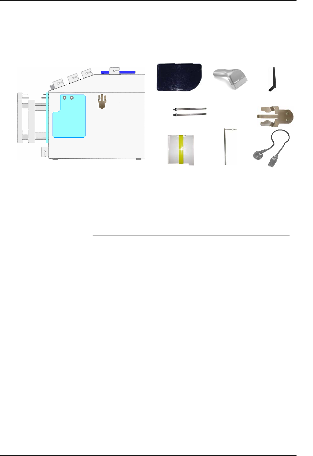
Picture 1: Parts included in the packing.
2.1 Unpacking Archimede
Remove Archimede from its packing. Take care not to crash the load cells.
Check that no part is damaged.
• Archimede is supplied with:
• Upper bag-holder plate and side scale-holders.
• Magnetic filter-holder. Pacemakers and floppy disk must keep away at least of 10 cm.
• WLAN antenna.
• Profile plate 2, 3, 4.
• Support bar.
• Power cable.
• Barcode reader.
2.2 Positioning Archimede
• Environmental conditions may affect Archimede operation. The following conditions
should therefore be avoided or minimized:
• High temperatures, elevated humidity, proximity of free flames.
• Direct sunlight exposure.
• Elevated dust accumulation.
• Proximity of flammable substances.
• Unstable and non-flat surfaces or slippy.
• Separation distance of 20 cm must be maintained between the WLAN antenna and
human bodies
2.3 Assembling scale, filter holders and antenna.
Lean the plastic plate on the upper scale holder. Screw the side scale holders paying attention
to the load cells: the load cells are mechanically protected but, they should not be hit with
force. Screw antenna and place it in vertical position. The filter holder is magnetic, and can be
put in the most suitable position to support the filter during the procedures requiring filter use.
Barcode
Power cable
Upper bag holder
Side scale holders Magnetic filter holder
Profile plate Support bar
INSTALLATION
Page 14 of 105 User Manual Revision 1.05
2.4 Switching on Archimede
The power cord must be plugged into a grounded power receptacle. When using an extension
cord, make sure it is properly grounded. Any rupture of the ground lead inside or outside the
instrument or a loose ground connection may result in hazardous operating conditions for the
operating personnel. Intentional disconnection of the grounding is not permitted.
The correct value of line voltage and line fuses are indicated on the rear plate of the
instrument.
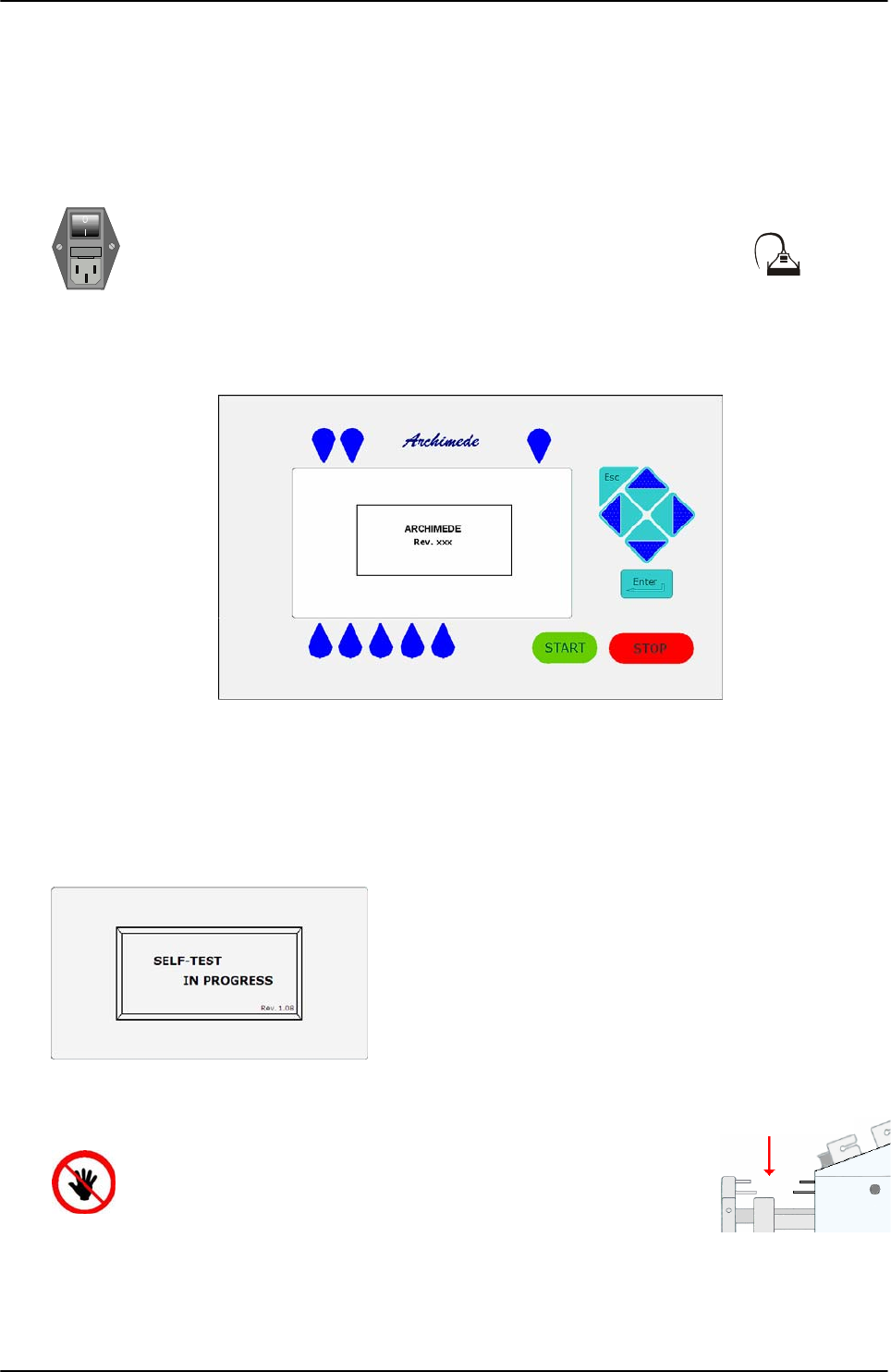
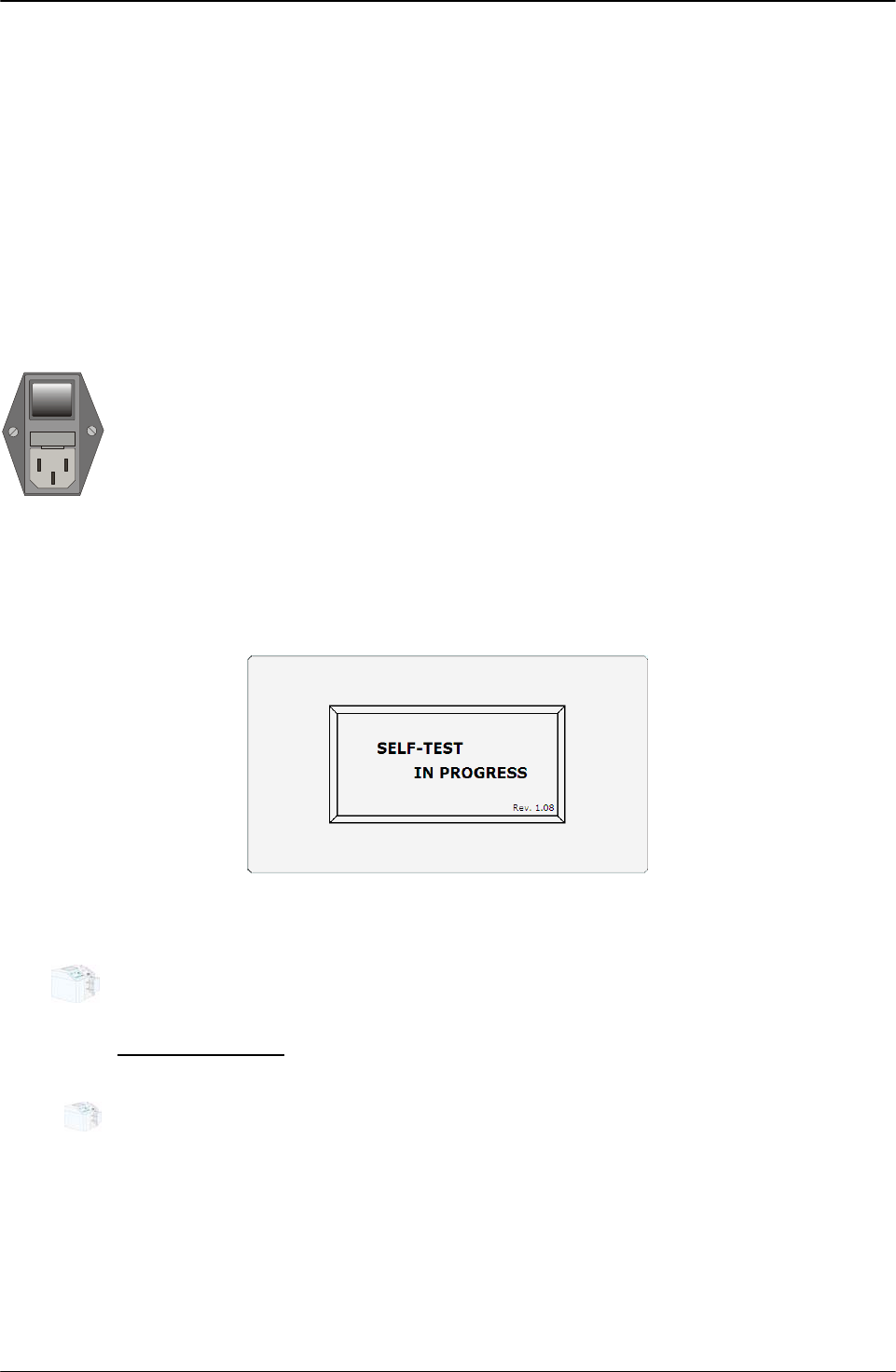
Check that mains power switch on rear left is in 0 position. Then
plug the Barcode Reader into the socket marked with
Plug the power cord and turn the main switch on.
Picture 2: Archimede display
If Archimede is not in Stand Alone mode but is connected with ArchimedeLINK in WLAN, before
proceed with the other controls it is necessary to set WLAN parameters. This configuration is
described in the service manual at the paragraph configuration WLAN.
When the display lights on, instrument model and firmware software revision number should
appear.
After verifying and initializing all data stored,
Archimede performs a self-check of all measurement
systems. In case of malfunction the display shows the
problem detected and the possible remedy.
Picture 3: Screen shot “Self Test”
ATTENTION: DO NOT PUT YOUR HANDS IN THE FRONTAL PRESS
PLATE WORKING AREA.
Press Plate Area
INSTALLATION
User Manual Revision 1.05 Page 15 of 105
2.5 Instrument Setup
All sensitive data are preset in a non volatile RAM. They can be modified using ArchimedeLINK.
Date and time are managed by a dedicated circuit that can operate for at least 60 days even
without main power. However, if Archimede does not operate in stand alone mode, date and
time are automatically updated when switching the instrument on, and get synchronized to
ArchimedeLINK. When using the instrument for the first time, date and time need to be
checked only if the system is not integrated with ArchimedeLINK.
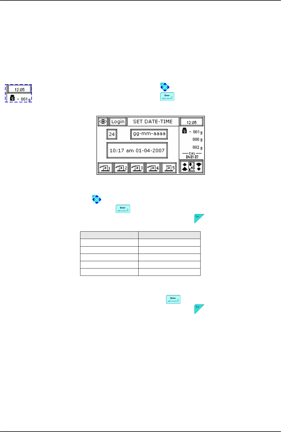
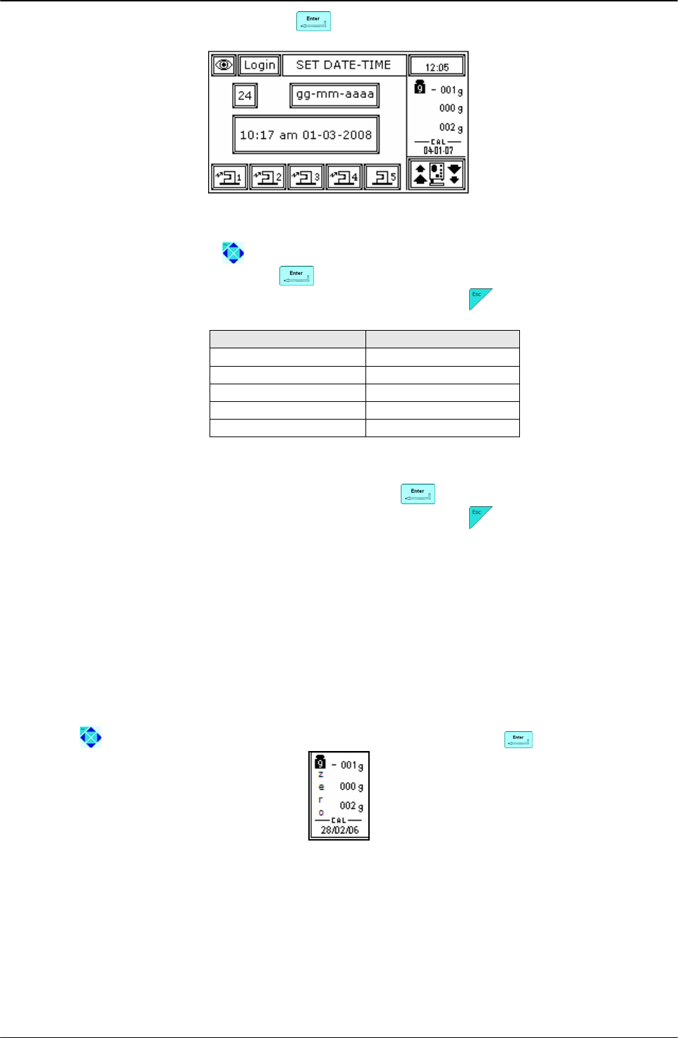
2.5.1 Date and Time
Using direction key-buttons highlight the display area indicating
current date and time. Press to enter modify mode.
Picture 4: Date and time menu.
Set date and time using keys , up and down key to increase or decrease value, left and
right to change the digit to modify and to confirm setting.
If you don’t want to confirm the date and time change, press key .
FORMAT READING
12 0-24
24 0-12 am/pm
dd-mm-yyyy 01-04-2008
mm-dd-yyyy 04-01-2008
yyyy-mm-dd 2008-04-01
Picture 5: Date and time format list.
Set current date and time, and confirm setting with key .
If you don’t want to confirm the date and time change, press key .
INSTALLATION
Page 16 of 105 User Manual Revision 1.05
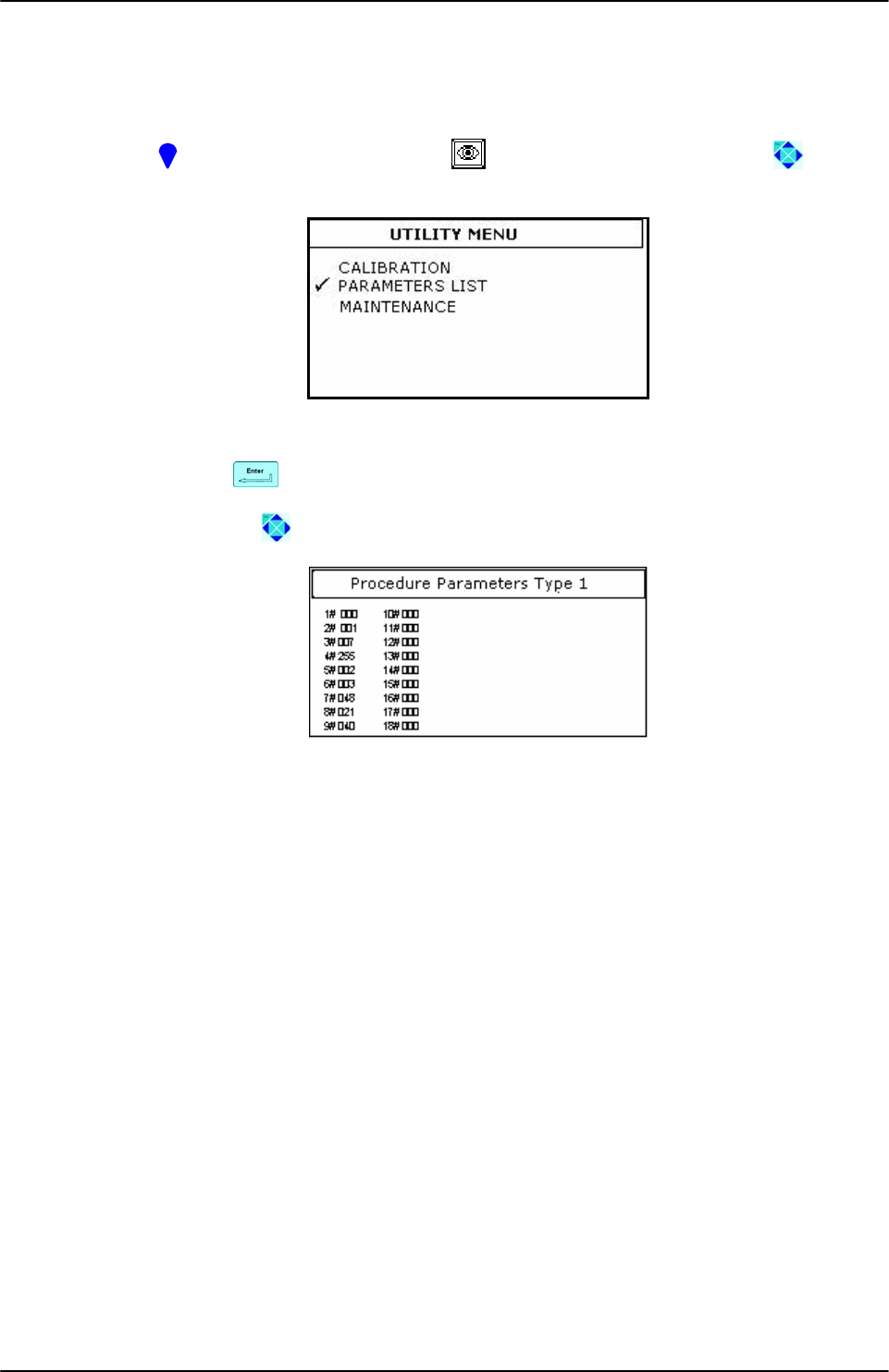
2.5.2 Procedures Setup Check
This check allows to verify all procedure parameters, and should be performed by the
application specialist or service engineering. Procedure parameters and their meaning are
described and can be set through ArchimedeLINK. The procedure is continuously displayed to
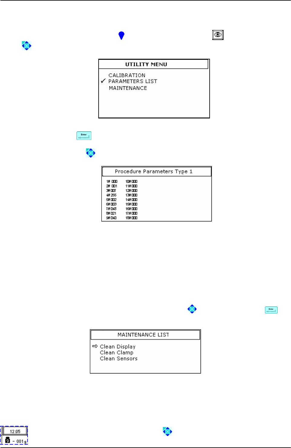
enable users (above all those working in stand alone mode) to verify its correctness. To enter
this menu press key-button above the icons and use direction key button to select
PARAMETER LIST.
Picture 6: Utility menu.
Confirm setting with key .
Using direction key-buttons it is possible to select the desired procedures.
Picture 7: Parameters procedures list
Archimedes due to its versatility enables automation combined with ease of use. It’s setup with
a minimum of standard procedures installed, implemented and modified through
ArchimedeLINK with the help of a technical application.
GENERAL DESCRIPTION
User Manual Revision 1.05 Page 17 of 105
3 GENERAL DESCRIPTION
Archimede consists of two parts:
• The electronic part includes a built-in microcontroller of the latest generation. Through
this microcontroller the instrument can store the procedures data, control graphic
display, drives motors, scales, sensors, clamps, sealer group and RFID reader.
• The mechanical part includes an axial system enabling movement of plate and buffy-
coat separation system.
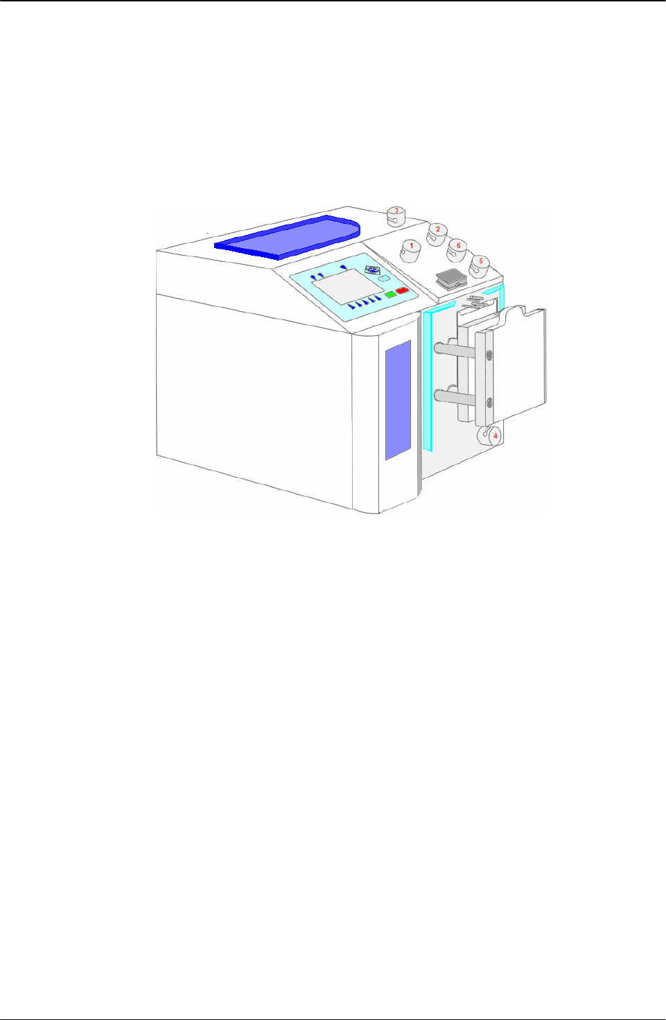
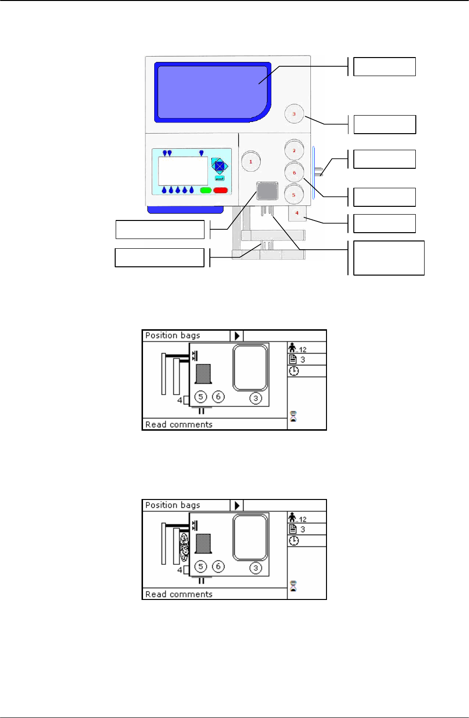
Picture 8: Global view
3.1 Upper Panel
The upper panel is designed to house tubes and collection bags. It includes:
• Upper scale, with removable plate; weight capacity 0-2000 grams with ± 1 g
resolution.
• Photometer for red blood cells detection. It consists of a 540 nm optical system and a
couple of IR sensors for air bubbles detection. A reflection optical systems detects cover
state (open/closed) and tube presence.
• Three sealing head clamps: “Top”, “Plasma”, and “Buffy Coat”; one normal clamp for
“Sag.M”.
• One proportional valve for plasma flow control.
• Holder for additional bag.
3.2 Front Panel
The front panel is designed to hold the bag from which the emocomponents are to be
extracted. It includes:
• Mobile separation plate controlled by one stepper motor and two sensors: the first
sensor detects the distance between plate and profile plate, the second sensor detects
the applied force.
• Fix plate provided with holders where the bag in use can be hanged.
• Primary bag support with bars for stainless-steel cannula breaking.
• Optical device for detection of buffy coat level. It consists of ten IR sensors linearity
placed.
• Clamp “Bottom” with sealing head.
• Sensor for detection of the type of plate in use.
GENERAL DESCRIPTION
Page 18 of 105 User Manual Revision 1.05
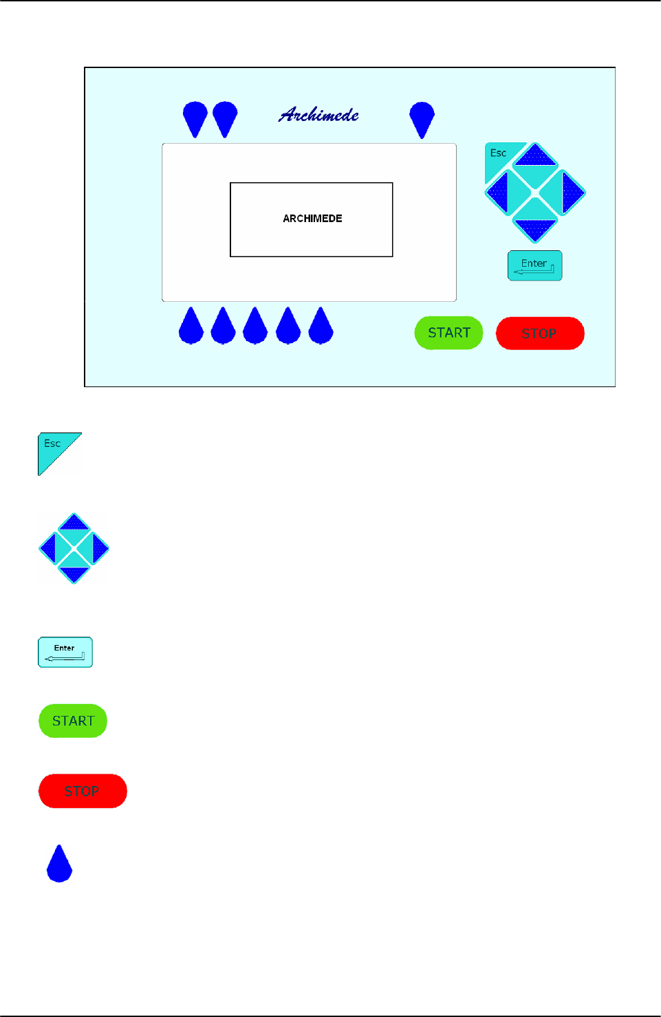
3.2.1 Keyboard
Some of the keyboard key-buttons are multifunction.
Picture 9: Keyboard
Allows to stop some functions and go back to the upper menu level.
Direction key-buttons: allow to move inside a menu and to change the
value of the selected function.
Allows to confirm the change or the selection.
Allows to start the separation procedure.
Allows to stop the ongoing procedure or application after confirmation.
Allows to start the displayed function.
GENERAL DESCRIPTION
User Manual Revision 1.05 Page 19 of 105
3.2.2 Backlight Display
The screen is a wide LCD 240 x 128 graphic display. It is backlit to improve reading in poorly
illuminated rooms.
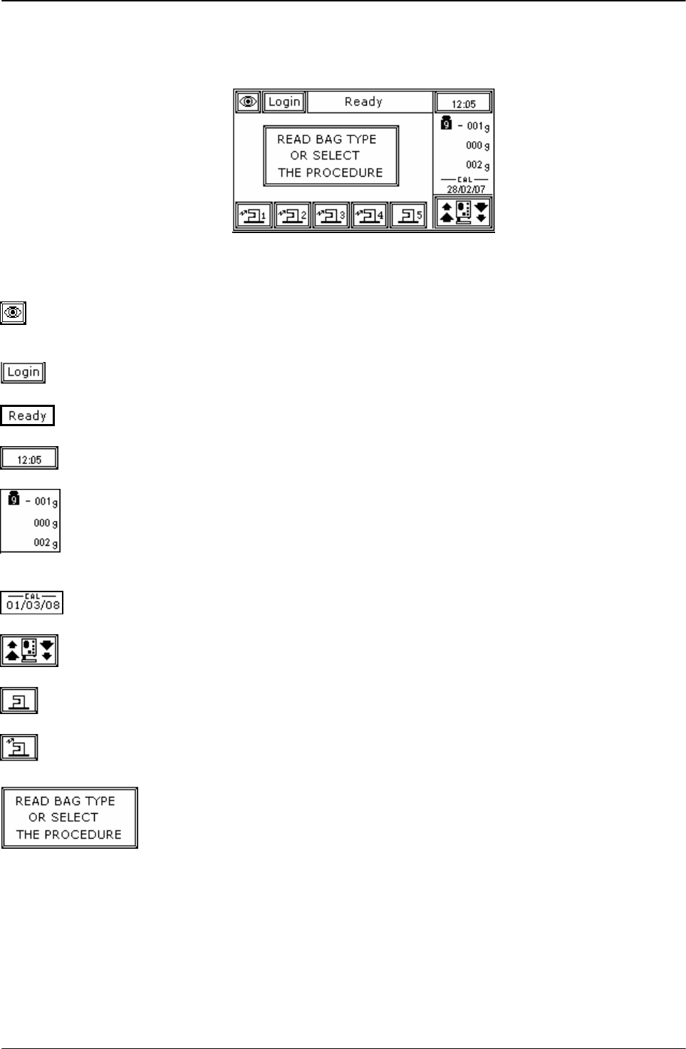
Picture 10: Main menu
Here is the meaning of the displayed functions:
This menu allows to enter submenus to have parameters and
maintenance actions displayed.
Press to login operator by bar code reader.
The instrument status is displayed in this area.
Current time is displayed in this area.
This menu allows to set the tare and to have front scale, upper scale and
side weight displayed.
Date of the last scales calibration is displayed in this area.
This function allows to move back and forth the pressing plate.
This function allows to open and close the selected clamp.
The arrow appears when the sealing is activated.
This function allows to enter the menu to select the desired procedure.
The procedure can be selected manually or through
BC reading of the type of bag.
GENERAL DESCRIPTION
Page 20 of 105 User Manual Revision 1.05
3.3 Rear Panel
The rear side includes the main power socket and two connectors that enable data exchange
with the barcode reader and with a host computer.
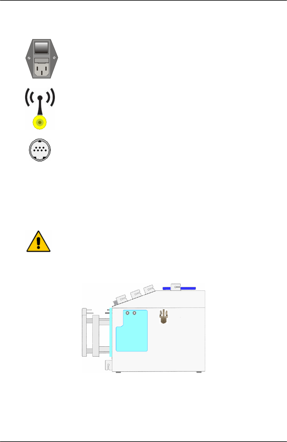
Power supply group including: power socket, On-Off switch, and fuse
holder.
Antenna for WLAN connection to ArchimedeLINK.
PS2 connector. Allows connection to barcode reader.
Yellow led it is:.
• Lit; when Archimede is not connected in WLAN.
• Flash: when Archimede search WLAN.
• Off: when Archimede is connected in WLAN.
Green led. It is not activated.
Designed by manufacturer for exclusive connection to the instrument
according to the prescriptions contained in the specific documentation of
that instrument and to EN60950 Regulation.
3.4 Side Panel
Picture 11: Lateral view
The right-side panel includes the support for lateral scale and the magnetic and removable
filter support. The filter support is to be used if required by the selected procedure.
0
I

GENERAL DESCRIPTION
User Manual Revision 1.05 Page 21 of 105
3.5 Meaning of Procedure Parameters
During the separation procedure Archimede operation is affected by several parameters. Some
of these parameters are fix, that is, preset by the management program. Other parameters
are variable, that is, settable by an application engineer through an external PC.
All variable parameters are factory preset and saved in a non-volatile memory with elevated
retention capacity.
Fix parameters are used to monitor all the events with top priority alarm, i.e.: time necessary
to enable all actuators very long, Sag. M dispensing time very long, etc.
In order to obtain a better management, procedure parameters are divided into group, defined
by their meaning:
General control
Parameters for procedure security control activation.
1 TUBES CHECK:
During the procedure, checks that tubes are properly inserted into the clamps enabled
for the ongoing procedure.
21 Sag.M. quantity:
Sag.M. amount already inside in the bag for RBC.
25 Main bag weight:
Weight of primary bag.
38 PLT FILTRATE FLOW ALARM :
Minimum flow that should pass through the filter. Below this value an alarm of
obstructed filter is activated.
41 Profile plate number:
Number of profile plate use in the procedure.
43 Primary Bag Positioning with Blade Ready for Weighing:
Enables blade coming out to move primary bag away from front panel and allow correct
weighing.
44 Scale Stability Check:
Enables check of weight stability as detected by enabled scales.
45 Check Correlation Distance Weight:
Check correlation between thickness bag and emocomponent weight.
46 Enable scale reading:
Must be inhibit in Archimede light version.
Initial phase
Parameters for Breaking Cannulas phase.
2 CANNULAS BREAKING ENABLING:
Enables the routine controlling breaking of the primary bag cannulas.
3 CANNULAS BREAKING THRESHOLD:
Force in xx.x Kg beyond which the plate stops and waits for cannulas breaking.
4 MOTOR SPEED DURING CANNULAS BREAKING:
Plate forward moving speed during cannulas breaking step.
5 CANNULAS BREAKING HYSTERESIS:
Value used to calculate the force value below which the system exits out of the cannulas-
breaking routine. V = (force measured at breaking position) – (current force).
24 MOTOR SPEED DURING FILTER PRIMING:
Plate forward moving speed during filter priming.
Optical sensor management
Parameters for manage optical sensors of Archimede (IR and RBC).

GENERAL DESCRIPTION
Page 22 of 105 User Manual Revision 1.05
6 NUMBER OF IR SENSOR USED TO ENABLE HB SENSOR:
Number identifying the IR sensor dedicated to RBC sensor activation.
RBC TARGET LEVEL: (PROCEDURE 8)
Value of IR - HB sensor to intercept the level of RBC.
7 MINIMUM OPTICAL GAP BETWEEN RBC AND PLASMA:
Value minimal of difference of reading between RBC and plasma with which it comes
controlled the bag before and during the procedure.
8 HB SENSOR SENSIBILITY:
Sensibility HB sensor.
10 IR SENSOR ACTION THRESHOLD:
Threshold value for action of IR sensors.
15 NUMBER OF IR SENSOR USED FOR CHECK BUFFY COAT LEVEL:
Decimal number identifying the IR sensor buffy coat level position.
HAEMATOCRIT SELECTION: (PROCEDURE 13)
Allows you to set the desired level of haematocrit, based on this value system displays the
number of IR LED concerned.
26 CLAMP CLOSURE DELAY TIME AFTER ERYTHROCITES LEVEL DETECTION
Delay time for clamp closure after detecting erythrocites level [0-25]s.
42 Air Elimination:
Allows to enable or inhibit the air elimination routine from plasma.
47 SELECTION OF IR CORRESPONDING TO UPPER AND LOWER BAG SIDE:
Allows to select the calibration sensors to be used to define the system’s optical
sensitivity. For optimum operation of the optical system, always select sensors within
lower and higher reflection area of the label. If this is not possible because the label is on
both sides, select so that the sensors can detect both plasma and RBCs.
Force management
Parameters for the force regulation system during the procedure.
9 MAXIMUM FORCE:
Value of the maximum force applied during the procedure; the plate stops if the force
exceeds this limit.
13 MOTOR SPEED IN AUTOLEARNING PHASE:
Plate moving speed used in the first phase for the management of force .
Seal management
Parameters the select witch clamps will seal and how the selected clamp will seal.
11 SEALING MODE:
Selection of the sealing mode. In automatic mode, the system automatically seals the
bags when the procedure is over. In manual mode, bags sealing must be confirmed.
12 SEALING CLAMPS SELECTION:
Selection of clamps to be used for sealing when the procedure is over. Clamps are
numbered as follows: 1 Top, 2 Plasma, 4 Buffy, 8 Bottom. The value to be set in this
position is the value corresponding to the sum of the clamps used: for example, if bottom
and top are to be used, the value to be set is 9.
40 Clamps Number:
Value allowing to select the clamps to be used in the procedure.
Maximum flow of Sag. M. supplied, beyond which the dispensing force decreases.

GENERAL DESCRIPTION
User Manual Revision 1.05 Page 23 of 105
Emocomponent volume
Parameters that define the Buffy Coat and the Sag.M. target volume.
18 RBCS NOT DETECTED FINAL DISTANCE WARNING:
Final distance value beyond which the system, after confirmation, stops the procedure if
RBCs have not been detected.
BUFFY COAT VOLUME:
Desired buffy coat volume.
INSUFFICIENT DISPENSED VOLUMES FINAL DISTANCE WARNING:
Final distance value beyond which the system, after confirmation, stops the procedure if
the set volumes have not been dispensed.
20 SAG. M. AMOUNT:
Sag. M. in [g] to be dispensed in the final step of the procedure.
22 BUFFY COAT AMOUNT WITHOUT BLADE SEPARATION:
Buffy coat [g] top be dispensed before mechanical blade separation.
23 BUFFY COAT ALARM DISTANCE:
Value of the distance beyond which the system, after confirmation, stops the procedure if
the desired buffy coat amount has not been collected.
29 ALIQUOT WEIGHT 1: ( UPPER SCALE)
Weight 1 desired for aliquot separation procedure.
14 ALIQUOT 2 WEIGHT: (UPPER SCALE)
Weight 2 desired for aliquot separation procedure.
30 PLASMA-PLT WEIGHT:
Value of the amount of plasma-plt to be separated.
37 BUFFY COAT TOTAL WEIGHT:
Total buffy coat weight.
39 ALIQUOT 3 WEIGHT: (LATERAL SCALE)
Weight 3 desired for aliquot separation procedure.
Secondary Emocomponent volume
Parameters that define the auto recover, wash or dilution and aliquot separation target
volume.
19 EXCESS PLASMA FOR FILTER:
Excess plasma [g] to be collected after the system has detected the buffy coat.
MANUAL DISPENSING:
Enables manual platelets recovery after detecting RBCs.
32 SENSIBILITY OF FLOW VALVE:
Adjust sensitivity of flow valve feedback. (Clamp 6)
34 PLASMA FOR BC DILUTION:
Amount of plasma to be added to the buffy coat when its separator is enabled.
35 Delay for BUFFY COAT LINE CLEANING WITH SAG.M.:
Delay for cleaning deviation of Buffy Coat line with Sag.M.
36 PLASMA AMOUNT FOR BUFFY COAT TUBE CLEANING:
Amount of plasma to be dispensed by gravity in the buffy coat bag.
GENERAL DESCRIPTION
Page 24 of 105 User Manual Revision 1.05
3.6 Procedure Parameters Display
Archimede is equipped with a long-retention internal memory. Up to 18 procedures can be
stored, with up to 40 parameters each.
To display procedure parameter press key-button above the icons and use direction key
button to select PARAMETER LIST.
Picture 12: Utility menu.
Confirm setting with key .
Using direction key-buttons it is possible to select the desired procedures.
Picture 13: Parameters procedures list
All procedures parameter values have been optimized in various testing centres. However,
parameter values can be changed by the application engineer through ArchimedeLINK to
improve the desired procedure.
3.7 Maintenance Display
Maintenance actions can be displayed only when Archimede is connected to ArchimedeLINK. In
this case, maintenance actions can be managed reporting to ArchimedeLINK any information,
including operator name and date of execution. It is also possible to schedule the desired
maintenance actions according to the Blood Transfusional Centre protocol. To confirm the
action performed, select maintenance type using the arrow , confirm by pressing and
read the operator code.
Picture 14: Maintenance list
3.8 Date and Time
Although the display normally shows only hours and minutes, Archimede is provided with a
built-in calendar used to send to ArchimedeLINK procedure data, including date and time.
Using direction key-buttons highlight the display area indicating
GENERAL DESCRIPTION
User Manual Revision 1.05 Page 25 of 105
current date and time. Press to enter modify mode.
Picture 15: Date and time menu.
Set date and time using keys , up and down key to increase or decrease value, left and
right to change the digit to modify and to confirm setting.
If you don’t want to confirm the date and time change, press key .
FORMAT READING
12 0-24
24 0-12 am/pm
dd-mm-yyyy 01-03-2008
mm-dd-yyyy 03-01-2008
yyyy-mm-dd 2008-03-01
Picture 16: Date and time format list.
Set current date and time, and confirm setting with key .
If you don’t want to confirm the date and time change, press key .
If the Blood Transfusional Centre uses ArchimedeLINK, date and time are automatically
updated when the instrument is switched on or at the first connection of the day. The PC date
and time are the reference data.
3.9 Scales
Archimede is provided with one front scale, one upper scale, and one side scale. All of them
have a weighing capacity up to 2 Kg with ± 1 g resolution. The scales are electronically
calibrated using a certified standard weight as a reference. The calibration date is highlighted
in the lower display area dedicated to weights. Calibration is performed using ArchimedeLINK.
The procedure is usually performed by a trained engineer authorized by the manufacturer.
Before using the system as a scale, it is necessary to set the tare value. Move the cursor using
the arrows until the display shows “zero” in the scales area. Press to zero all values.
The bag or product you have to weight can be hanged to the front scale or to the side scale, or
placed on the upper scale.
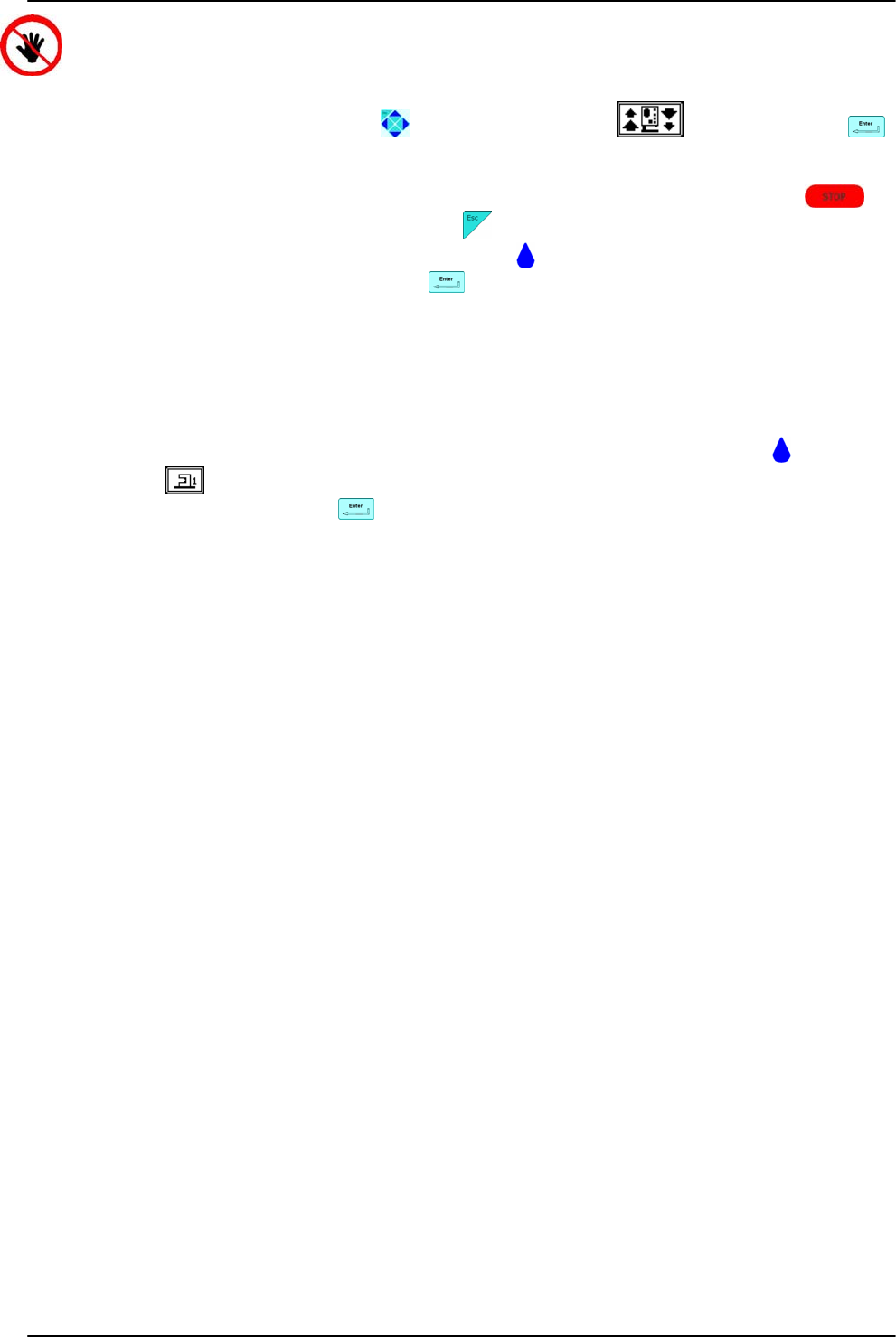
3.10 Manual Control of Plate Forward Moving
The plate can be manually moved forward and backward. This can be useful both if you want
to press a bag manually, and if you want to check that the movement axial system is working
correctly.
GENERAL DESCRIPTION
Page 26 of 105 User Manual Revision 1.05
CAUTION: DO NOT PUT YOUR HANDS IN THE PLATE WORKING AREA.
To enter this mode, use the arrows to highlight the icon , and then press ..
Now move the arrows up and down to move the plate in the desired direction. The forward
moving is always controlled by the maximum applied force, while the backward moving is
controlled by open plate limit switch. To stop the plate and keep the position press ; to
exit and put the plate in standby position press .
This mode also allows to enable clamps by pressing ; if the clamp is closed and the tube is
in position it is possible to seal by pressing .
Clamp number 5 of Sag. M. is not provided with sealing head, therefore cannot be used as a
sealer.
3.11 Clamps Manual Control
All mounted clamps can be manually controlled with the exception of the flow clamp. This can
be useful during the use of manual plate movement and to seal tubes to the bags.
The clamps positions change from open to closed and vice versa by pressing the key-button
under the icon . If the highlighted clamp has to be used as a sealer, insert the tube to be
sealed in the clamp and press . The sealing cycle is inhibited in case the electronic
protection implemented in the CSU detects the presence of moisture on the sealing clamp.
Clamp 5 of Sag. M. is not provided with sealing head and therefore cannot be used as a sealer.
USING ARCHIMEDE
User Manual Revision 1.05 Page 27 of 105
4 USING ARCHIMEDE
Using Archimede in separation mode is simple thanks to the built-in microcontroller. The
microcontroller constantly checks the following parameters: buffy coat level, RBCs presence,
weights, distance between plate and profile plate, separation speed, separation force,
maximum settable force, correct program performance.
If connected to ArchimedeLINK, Archimede sends all sensor and procedure data, including
those acquired by the barcode reader. In stand alone mode data are store into a FIFO memory
and should be sent automatically to ArchimedeLINK on next connection.
4.1 Switching on
The switch on procedure includes a complete self-check of the system. Before switching
Archimede on it is therefore necessary to remove any bag and check that the bags holders are
free and correctly placed.
After plugging the power cable, turn on the main switch on instrument rear.
The display should be back lighted and show “ARCHIMEDE”. If not, check that the
power cable is well plugged and that the power socket in use is powered.
If the display does not light up, please see Troubleshooting section.
4.2 System Self-check
Every time it is turned on, Archimede performs a self-check to verify proper system operation.
Picture 17: Screen shot “Self-Test in progress”
The actions performed following a negative check depend on the connection mode
Stand Alone or ArchimedeLINK.
E2prom Memory
Check of data integrity concerning calibration and procedure parameters.
If data are incorrect, the system, after confirmation, will initialize them and
restore the factory set values.
Procedure data are restore to factory set values, while calibration data will require
a new calibration.
0
I

USING ARCHIMEDE
Page 28 of 105 User Manual Revision 1.05
Clock
Date and time check.
If date and time values are incompatible with the format, the system, after
confirmation, will initialize them at 00:00:00 01/03/08.
Synchronization with data and time of ArchimedeLINK Server.
Scales
Tare check of all scales.
If the tare values are not within the preset limits, an error alarm will be sent and
displayed.
If the problem persists, please see the Troubleshooting section.
Same as in stand alone mode.
Plate motor
Check of motor movement and limit switch.
If limit switches are not enabled within the preset travel limits, an error alarm will
be sent and displayed. If the problem persists, please see the Troubleshooting
section.
Same as stand alone mode.
Buffy-coat separation motor
Check of motor movement and limit switch.
If limit switches are not activated within the preset travel limits, an error alarm
will be sent and displayed. If the problem persists, please see the Troubleshooting
section.
Same as stand alone mode.
IR sensors
IR sensors check and self-calibration.
If IR sensors have an elevated dark current or a low sensibility, an error alarm will
be sent and displayed. If the problem persists, please see the Troubleshooting
section.
Same as stand alone mode.
Force sensor
Force sensor check.
If the force detected by the sensor is over the preset limits, an error alarm will be
sent and displayed. If the problem persists, please see the Troubleshooting
section.
Same as stand alone mode.
HB sensor
HB sensor check and self-calibration.
If the HB sensor has an elevated dark current or a low sensibility, an error alarm
will be sent and displayed. If the problem persists, please see the Troubleshooting
section.
Same as stand alone mode.

USING ARCHIMEDE
User Manual Revision 1.05 Page 29 of 105
CSU
Check of sealing unit and tubes detector.
If the CSU state is not “ready”, and if there are moisture or tubes within clamps,
an error alarm will be sent and displayed. If the problem persists, please see the
Troubleshooting section.
Same as stand alone mode
Flow control clamp
Actuator movement check.
If the limit switch is not activated within the preset travel limits, an error alarm
will be sent and displayed. If the problem persists, please see the Troubleshooting
section.
Same as stand alone mode.
USING ARCHIMEDE
Page 30 of 105 User Manual Revision 1.05
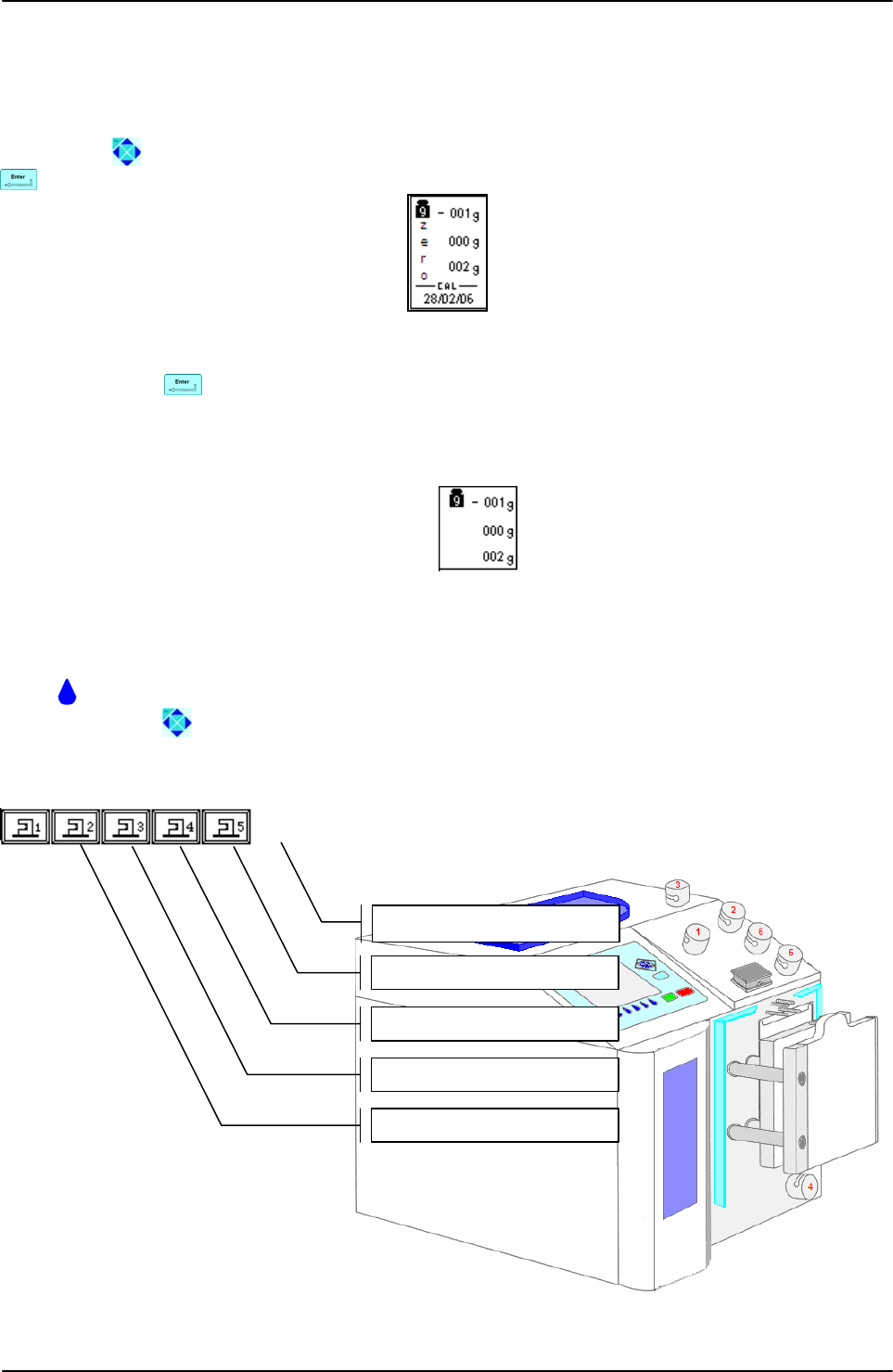
4.3 Use as a scale
Archimede can be used as a weighing system thanks to its three load cells. The maximum
measurable weight is 2 Kg with 1 g resolution.
Before using the system as a scale, it is necessary to calculate the tare. Move the cursor using
the arrows until the word “zero” is displayed in the scales area of the screen and press
to zero the values.
Picture 18: Scale tare
Now use the arrows to move the cursor to another option; this will avoid performing another
tare by pressing key-button unintentionally
Take the product you wish to weigh and hang it to the front or side scale, or put it on the
upper scale.
Weights are displayed in the following order:
Picture 19: Reading scale area
4.4 Use as a sealing unit
Archimede can be used as a sealing unit thanks to its four built-in sealing heads.
Press key-button below the sealing head that you wish to use or highlight the sealing head
using the arrows .
Location of the sealing heads is as follows:
Picture 20: Archimede view
[
4
]
SEALING HEAD
[
3
]
SEALING HEAD
[
2
]
SEALING HEAD
[
1
]
SEALING HEAD
[5] NON-SEALING HEAD
Front scale
Upper scale
Side scale
USING ARCHIMEDE
User Manual Revision 1.05 Page 31 of 105
To perform sealing with the selected sealing head, press key-button. If you don’t want to
seal but, you want to open or close the selected clamp, press . Sealing operation will be
shown on left side of the clamp by the symbol .
In case any error occurs, this will be displayed in the notice window of the screen:
• Clean sealing head: the CSU has detected some moisture; it is necessary to clean
sealing head and tube and check for leakages.
• Insert tube: the tube sensor has detected that the tube is missing or incorrectly
inserted in the sealing head clamp.
• CSU busy: the CSU is busy with a sealing cycle; retry after a few seconds.
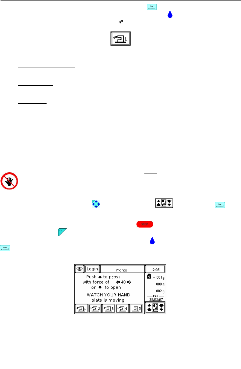
4.5 Use as manual separator
Archimede can also be used as a manually controlled separator.
In this mode the enabled checks are the following:
• Position sensor determining the plate standby position.
• Force sensor determining plate stop if the applied force exceeds the set value. When
the applied force decreases below the value calculated according to the hysteresis, the
plate starts again. The values set for force and hysteresis are those set during the first
active procedure.
ATTENTION: THE FORCE SENSOR IS ENABLED ONLY WHEN THE PLATE MOVES TOWARDS
THE INSTRUMENT BODY.
CAUTION: DO NOT PUT YOUR HANDS IN THE PLATE WORKING AREA WHEN THE PLATE IS
MOVING.
To enter this mode, use the arrows to highlight the icon and then press . Now
press the arrows up or down to move the plate in the desired direction, and press the arrows
left or right to change the applied force with fix increments of 5 units.
To stop the plate and maintain the position press ; to exit and move the plate to
standby position press .
In this mode you can also enable the clamps by pressing key-button, and seal by pressing
key-button.
Clamp 5 of Sag. M. is not provided with sealing head and cannot be used as a sealer.
Picture 21: Manual movement window
USING ARCHIMEDE
Page 32 of 105 User Manual Revision 1.05
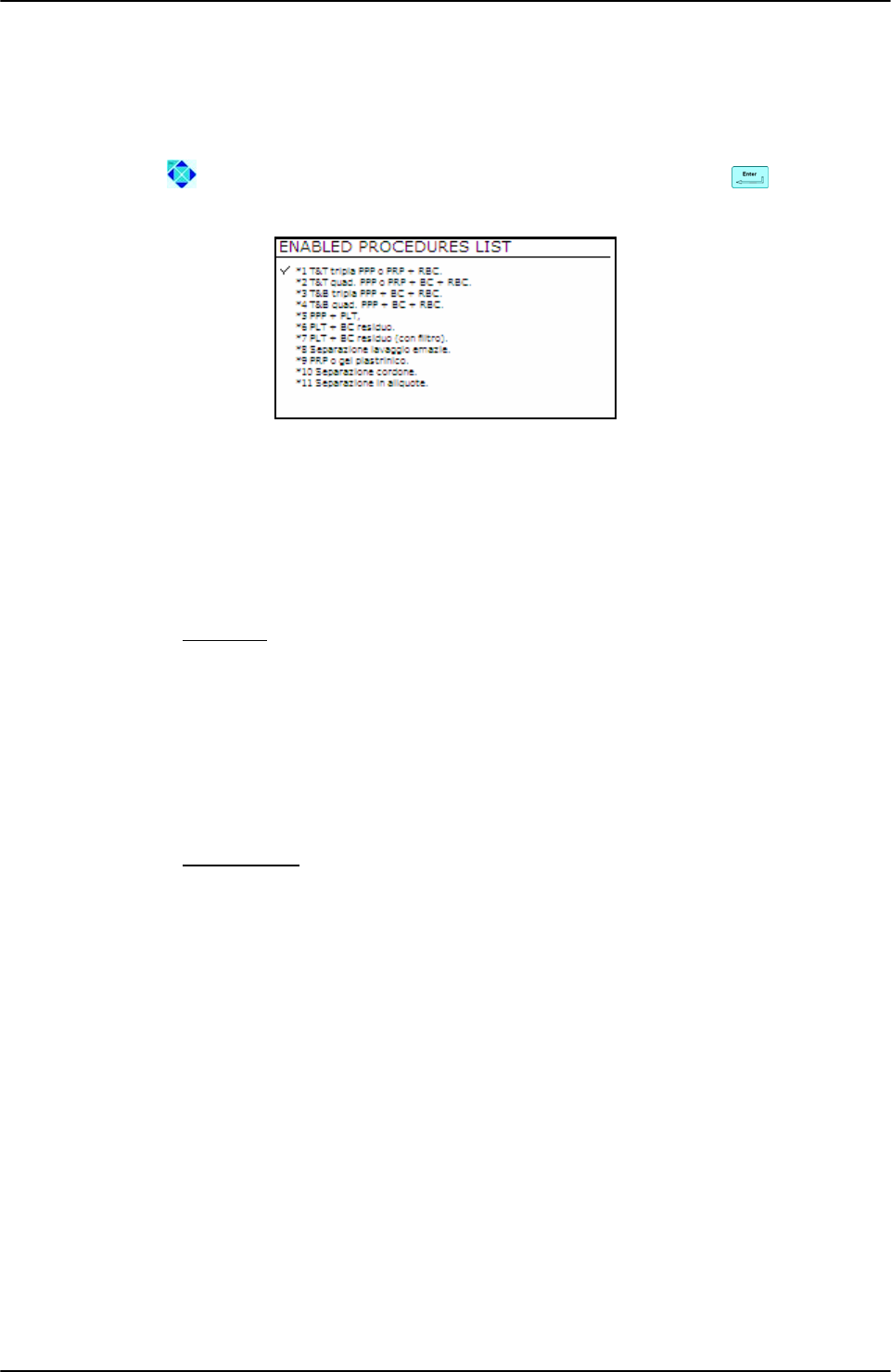
4.6 Separation Procedure
Archimede can store up to 18 procedures. The operator can perform a manual selection or an
automatic selection if the system is connected to ArchimedeLINK.
• Manual mode: To speed up procedures selection, the system can be configured to show
only the procedures enabled. In this way, only the procedures most frequently used in the
blood transfusional center will be displayed.
Using the arrows highlight the procedure you intend to use, then press to start the
procedure.
Picture 22: Enable procedures list
• Automatic mode: Using ArchimedeLINK it is possible to associate a bag type to a
procedure type. In this way, from the main menu you will only have to read the bag type
barcode and ArchimedeLINK will transmit to Archimede what type of procedure it has to
run.
The separation procedures presently available are:
PRIMARY
# 1 T & T triple PPP or PRP + RCC.
# 2 T & T quadruple PPP or PRP BC + RCC.
# 3 Top & Bottom triple PPP+BC+RCC.
# 4 Top & Bottom quadruple PPP+BC+RCC.
# 10 [a] Cord separation.
# 11 [b] Aliquot separation.
# 13 [d] Procedure Top & Top RBC with PPP + PPP.
SECONDARY
# 5 PPP + PLT.
# 7 PLT + residual BC with filter.
# 8 Erythrocytes washing separation.
USING ARCHIMEDE
User Manual Revision 1.05 Page 33 of 105
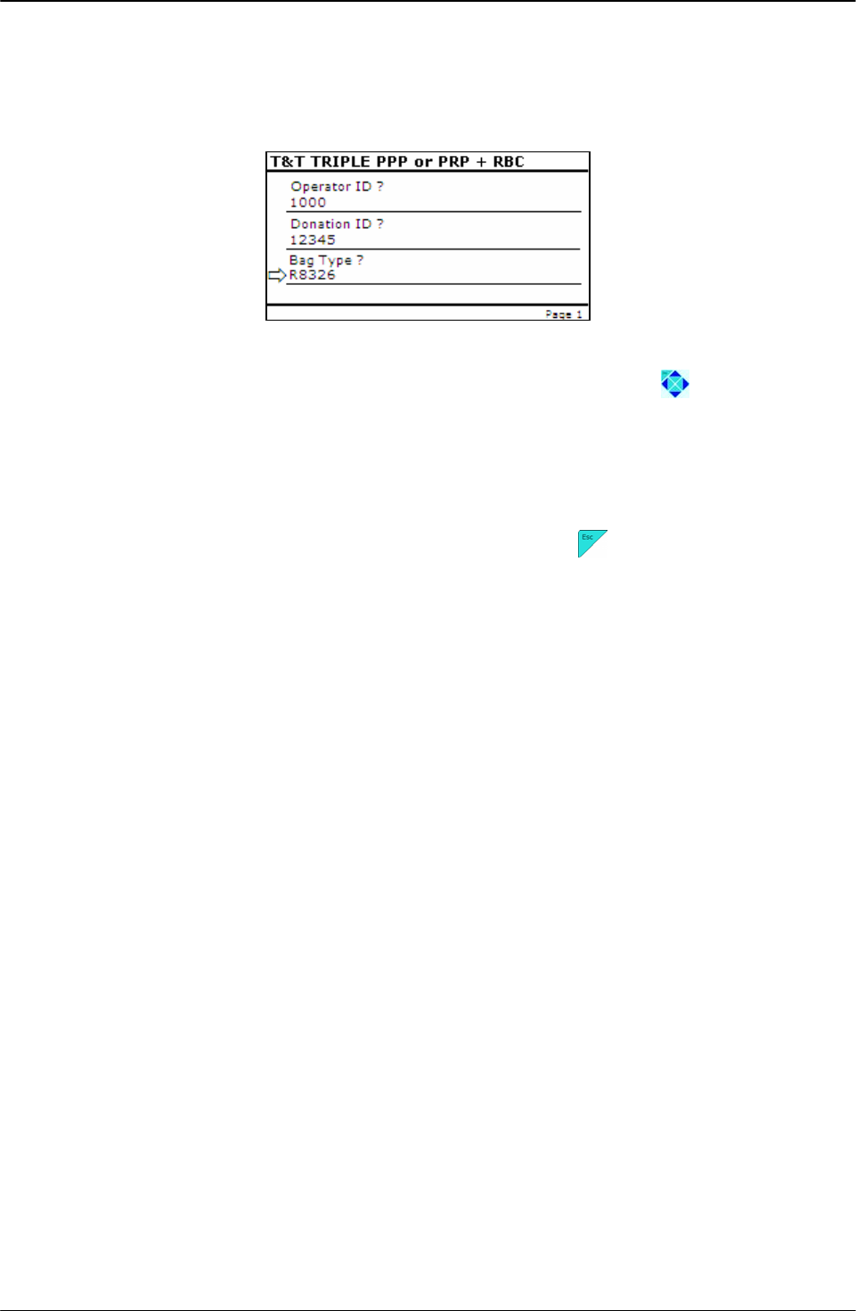
4.6.1 Questions
This mode (not available in stand alone mode) allows complete procedures traceability. With
ArchimedeLINK it is possible to define a series of questions to be asked soon after choosing
the procedure to be used. The replies will be checked according to various criteria: length,
barcode type, character type, authorized operators IDs, donors IDs, bag lot validation.
Picture 23: Questions view
To reply to the question indicated by the arrow, read the barcode of the item concerned. If you
need to read a reply again, move the arrow indicating the question using key-buttons.
Once the system has selected the type of procedure to be used, it is no longer possible to
modify the reply to donor ID and operator ID. Actually, the choice criteria of the procedure
take into consideration both operator’s privileges and status of primary and secondary
separation. Example: if a bag has already been processed as primary-secondary procedure,
ArchimedeLINK will not allow the separation unless an operator having the due privileges
forces it to do so.
To clear the series of questions and return to main menu, press .
When all questions have been replied to, the initial display of the selected procedure will
automatically appear.

USING ARCHIMEDE
Page 34 of 105 User Manual Revision 1.05
4.6.2 PROCEDURE 1 T & T triple PPP or PRP + RCC.
This procedure is suitable for triple bags containing Sag. M. It allows erythrocytes separation
(RCC) and platelets poor plasma (PPP).
Parameters used:
1 During the procedure, checks that tubes are properly inserted into the clamps enabled
for the ongoing procedure.
2 Enables the routine controlling breaking of the primary bag cannulas.
3 Force in xx.x Kg beyond which the plate stops and waits for cannulas breaking.
4 Plate forward moving speed during cannulas breaking step.
5 Value used to calculate the force value below which the systems exits the cannulas
breaking routine. V =(force measured at breaking position) – (current force).
6 Number identifying the IR sensor dedicated to RBC sensor enabling.
7 Value minimal of difference of reading between RBC and plasma with which it comes
controlled the bag before and during the procedure
8 Sensibility HB sensor.
9 Value of the maximum force applied during the procedure; the plate stops if the force
exceeds this limit.
11 Selection of the sealing mode. In automatic mode, the system automatically seals the
bags when the procedure is over. In manual mode, bags sealing must be confirmed.
12 Selection of clamps to be used for sealing when the procedure is over. Clamps are
numbered as follows: 1 Top, 2 Plasma, 4 Buffy, 8 Bottom. The value to be set in this
position is the value corresponding to the sum of the clamps used: for example, if
bottom and top are to be used, the value to be set is 9.
13 Plate moving speed used in the first phase for the management of force
18 Value of the distance beyond which the system, after confirmation, stops the procedure if
no RBCs have been detected.
19 Excess plasma [g] to be collected after the system has detected the buffy coat.
20 Sag. M. amount [g] to be dispensed in the final step of procedure.
25 Tara sacca primaria. Valore utilizzato per calcolare la quantità di prodotto rimasto nella
sacca primaria. [peso attuale-tara]
26 Threshold value used to detect air bubbles during procedures requiring its elimination.
40 Value allowing to select the clamps to be used in the procedure.
41 Number of the profile plate to be used with the ongoing procedure.
42 Enables the air elimination routine.
43 Primary bag positioning with blade ready for weighing.
44 Scale stability check.
45 Check Correlation Distance Weight.
46 Enable scale reading.
47 IR corresponding to higher and lower bag edge.
USING ARCHIMEDE
User Manual Revision 1.05 Page 35 of 105
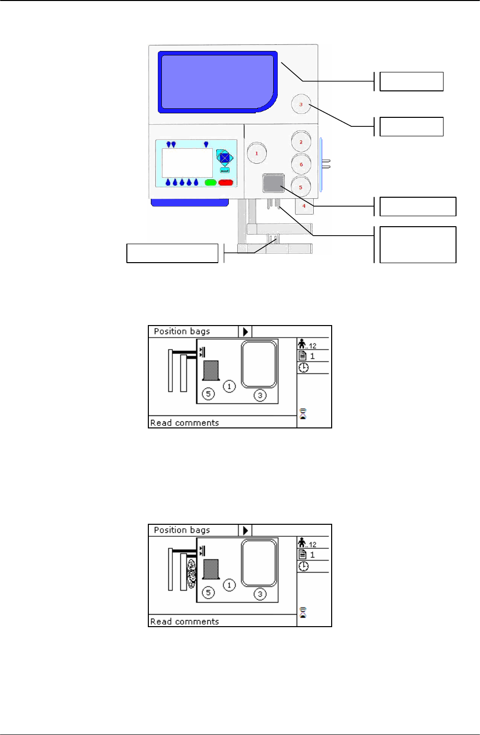
Position bags and tubes according to the below sequence. Be sure to avoid tensions and folds
that might cause flow obstruction or weighing errors.
Picture 24: Kit installation procedure T/T triple
NOTE: Tubes in the various kits have different lengths. To simplify kits management, the
firmware allows to configure which valves you wish to enable.
Picture 25: Position primary T/T triple bag.
Hang the primary bag to the bag holders on the front panel. The label containing bag data
should always be turned outside. After detecting the primary bag, the plate will move
backword to make positioning of Sag.M. bag easier, and the display will show the bag
icon.
Picture 26: Position plasma and Sag.M. T/T triple bags.
Hang the Sag. M. bag to the bag holders on the fix plate.
Insert the Sag. M. tube firmly into clamp 5.
Open the cover of HB sensor and insert the tube coming from the primary bag into the
reading area. Close the cover.
Insert the tube coming from the RBC sensor firmly into clamp 3.
Position the plasma bag on upper scale.
Primary bag
Scale 1
Sa
g
. M. ba
g
RBC Sensor
Clam
p
3
Scale 2
USING ARCHIMEDE
Page 36 of 105 User Manual Revision 1.05
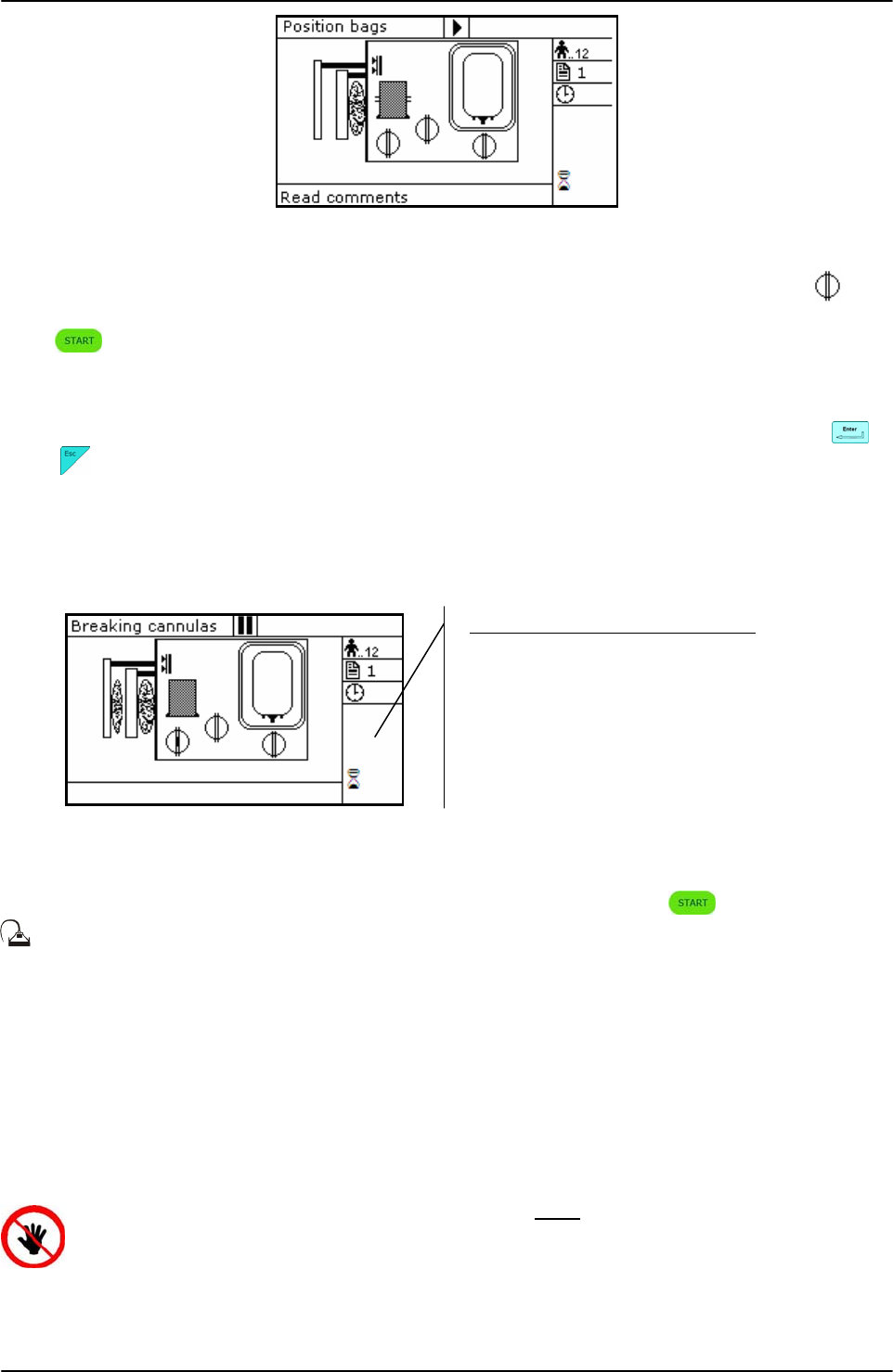
Picture 27: T/T Triple bags in position.
Archimede checks correct tubes positioning inside proper clamps by means of its optical
sensors. The tube is correctly inserted when the clamp number is replaced by the icon .
Press key-button to start the procedure.
If the primary bag expected weight check has been enabled through ArchimedeLINK and the
detected weight does not fall within the set limits, a warning will be displayed showing both
limits and current weight. After verifying the cause of the problem, confirm weight with or
press to leave the procedure. Furthermore, if the tube presence check is enabled the
display will show the clamp numbers where tubes are not correctly inserted and the procedure
will not start until all tubes are correctly inserted into the enabled clamps.
Now wait for the plate to get close to the bag. The plate will exert a force corresponding to the
value set in the procedure parameters.
Picture 28: Break cannulas view T/T triple procedure.
Break the cannules by forcing on their side upper part, and wait a few seconds for positive
pressure release. After detecting pressure decrease, Archimede automatically starts the
separation cycle. If pressure does not decrease below the set value, due to tube obstruction or
fluid clogging, it is anyway possible to force the cycle start by pressing keybutton.
During the procedure, possible comments can be read on the external part of the fix
front plate.
The graphic interface will now show the current operating phase number, and the weight value
of plasma collected. Archimede will check the erythrocytes level in the primary bag. When this
level reaches the selected IR sensor, the display will show it in the area of the RBC-pressing
plate. The photometer detecting the presence of erythrocytes will now check, in real time, the
plasma flow. When the erythrocytes amount exceeds the value set in procedure parameters,
the photometry will display “RBC” on the sensor cover icon and, if dispensation of excess
plasma is not provided, the separation process will stop and the plate will move backwards to
allow Sag. M. dispensing.
ATTENTION: THE FORCE SENSOR IS ENABLED ONLY WHEN THE PLATE MOVES TOWARDS
THE INSTRUMENT BODY.
CAUTION: DO NOT PUT YOUR HANDS IN THE PLATE WORKING AREA WHEN THE PLATE IS
MOVING.
If air elimination is enabled, the system will send the air contained in the primary bag into the
Sag.M. bag both at the initial and final stage.
Parameters of the ongoing phase:
#13: Plate forward moving speed
#18: Action distance
#8: RBC action threshold
#19: Excess plasma for filter
#20: Sag. M. amount
USING ARCHIMEDE
User Manual Revision 1.05 Page 37 of 105
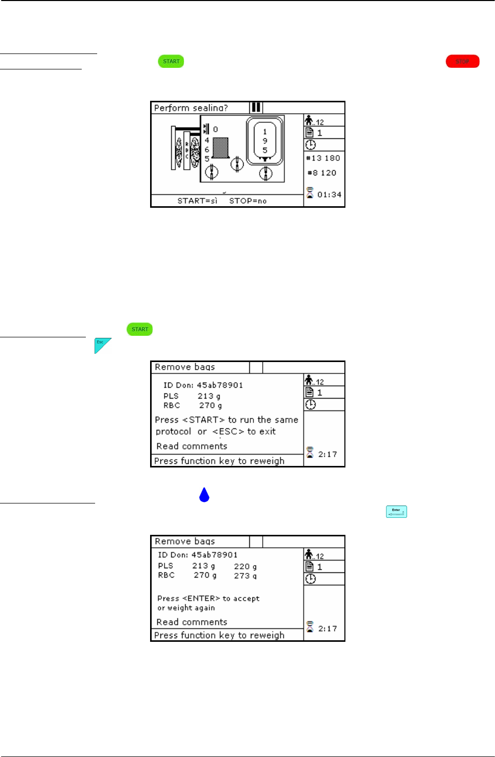
The sealing cycle depends on the value set in the procedure parameters;
Automatic sealing: sealing cycle of the selected clamps is performed automatically.
Manual sealing: press keybutton to seal the enabled lines, or press to
continue, after confirming, without sealing.
Picture 29: Sealing procedure T/T triple
Archimede will automatically send to ArchimedeLINK all events and data of the procedure
performed.
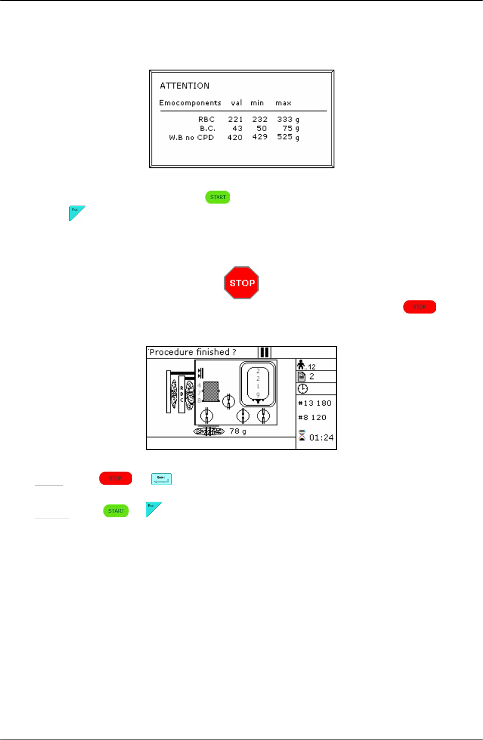
At the end of the procedure the display will show the detected weights. If they are not the
expected ones, because tubes are not correctly placed and distort scales’ readings, the
emocomponents can be weighed again after correcting tubes’ position and the new weights
can be sent to ArchimedeLINK again.
Correct weights: press keybutton to continue with the same type of separation or press
to go back to the page listing the procedures.
Picture 30: Viewing weights T / T triple.
Incorrect weights: press one of the keybuttons to weigh emocomponents again. To accept
the new values and send them to ArchimedeLINK press
Picture 31: Reweigh T/T quadruple.
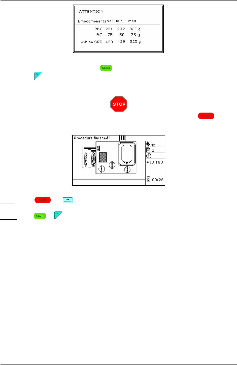
With ArchimedeLINK the normal limits check can be activated. If it is enabled and the detected
weights do not fall within the set limits, the display will show the emocomponents’ detected
weights and the allowed limits. Press any key to continue.
USING ARCHIMEDE
Page 38 of 105 User Manual Revision 1.05
Picture 32: T/T quadruple with weight out of normal range.
Now remove tubes and bags and press to continue with another separations of the same
type or press to exit.
If you need to interrupt the procedure either momentarily or definitively, press
keybutton.
Picture 33: Pause or Stop procedure T/T triple.
Stop: press or . Archimede will display the sealing page and send data to
ArchimedeLINK.
Pause: press or to continue the procedure.

USING ARCHIMEDE
User Manual Revision 1.05 Page 39 of 105
4.6.3 PROCEDURE 2 T & T quadruple PPP or PRP BC + RCC.
This procedure is suitable for quadruple bags containing Sag. M. It allows to separate
erythrocytes (RCC), platelets poor plasma (PPP) and buffy coat.
Parameters used:
1 During the procedure, checks that tubes are properly inserted into the clamps enabled for
the ongoing procedure.
2 Enables the routine controlling breaking of the primary bag cannulas.
3 Force in xx.x Kg beyond which the plate stops and waits for cannulas breaking.
4 Plate forward moving speed during cannulas breaking step.
5 Value used to calculate the force value below which the systems exits the cannulas
breaking routine. V =(force measured at breaking position) – (current force).
6 Number identifying the IR sensor dedicated to RBC sensor enabling.
7 Value minimal of difference of reading between RBC and plasma with which it comes
controlled the bag before and during the procedure
8 Sensibility HB sensor.
9 Value of the maximum force applied during the procedure; the plate stops if the force
exceeds this limit.
11 Selection of the sealing mode. In automatic mode, the system automatically seals the
bags when the procedure is over. In manual mode, bags sealing must be confirmed.
12 Selection of clamps to be used for sealing when the procedure is over. Clamps are
numbered as follows: 1 Top, 2 Plasma, 4 Buffy, 8 Bottom. The value to be set in this
position is the value corresponding to the sum of the clamps used: for example, if bottom
and top are to be used, the value to be set is 9.
13 Plate moving speed used in the first phase for the management of force.
16 Plasma to dilute Buffy Coat.
18 Value of the distance beyond which the system, after confirmation, stops the procedure if
no RBCs have been detected.
19 Excess plasma [g] to be collected after the system has detected the buffy coat.
20 Sag. M. amount [g] to be dispensed in the final step of procedure.
22 Buffy coat amount [g] to be dispensed before mechanical separation.
23 Value of the distance beyond which the system, after confirmation, stops the procedure if
the desired buffy coat amount has not been collected.
25 Tare of the primary bag. This value is used to calculate the product amount left in the
primary bag. [current weight - tare]
34 Amount of plasma to be dispensed in the buffy coat bag.
35 Delay for cleaning deviation of Buffy Coat line with Sag.M.
36 Amount of plasma to be dispensed by gravity in the buffy coat bag.
40 Value allowing to select the clamps to be used in the procedure.
41 Number of the profile plate to be used with the ongoing procedure.
42 Enabling of the air elimination routine.
43 Primary bag positioning with blade ready for weighing.
44 Scale stability check.
45 Check Correlation Distance Weight.
46 Enable scale reading.
47 IR corresponding to upper and lower bag edges.
USING ARCHIMEDE
Page 40 of 105 User Manual Revision 1.05
Position bags and tubes according to the below sequence. Be sure to avoid tensions and folds
that might cause flow obstruction or weighing errors.
Picture 34: Kit installation T/T quadruple procedure.
NOTE: Tubes in the various kits have different lengths. To simplify kits management, the
firmware allows to configure which valves you wish to enable.
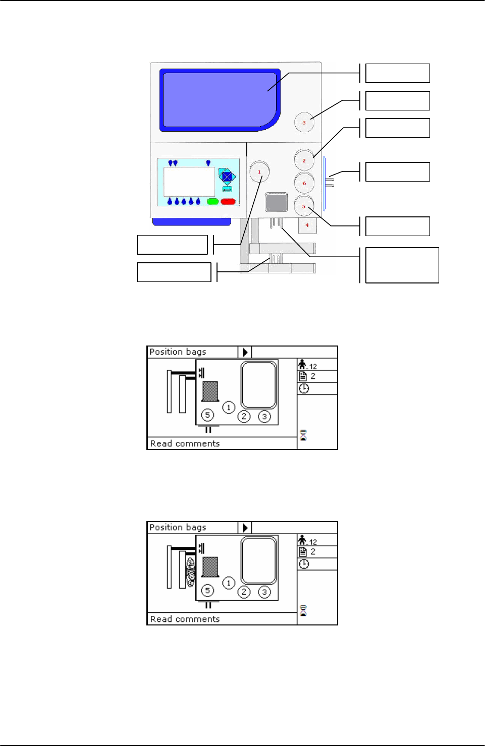
Picture 35: Position primary T/T triple bag.
Hang the primary bag to the bag holders on the front panel. The label containing bag data
should always be turned outside. After detecting the primary bag, the plate will move
backword to make positioning of Sag.M. bag easier, and the display will show the bag icon.
Picture 36: Position plasma, buffy coat and Sag.M. T/T quadruple bags.
Hang the Sag. M. bag to the bag holders on the fix plate.
Insert the Sag. M. tube firmly into clamp 5.
Open cover of HB sensor and insert the tube coming from the primary bag into the reading
area. Close the cover.
Insert the tube coming from the HB sensor firmly into clamp 1.
Insert buffy coat tube into clamp 3.
Insert the plasma tube into clamp 2.
Primari bag
Scale 1
Sa
g
. M. ba
g
Clam
p
2
Scale 2
Clam
p
3
Scale 3
Clam
p
1
Clam
p
5
USING ARCHIMEDE
User Manual Revision 1.05 Page 41 of 105
Position the plasma bag on upper scale.
Position the buffy coat bag on lateral scale.
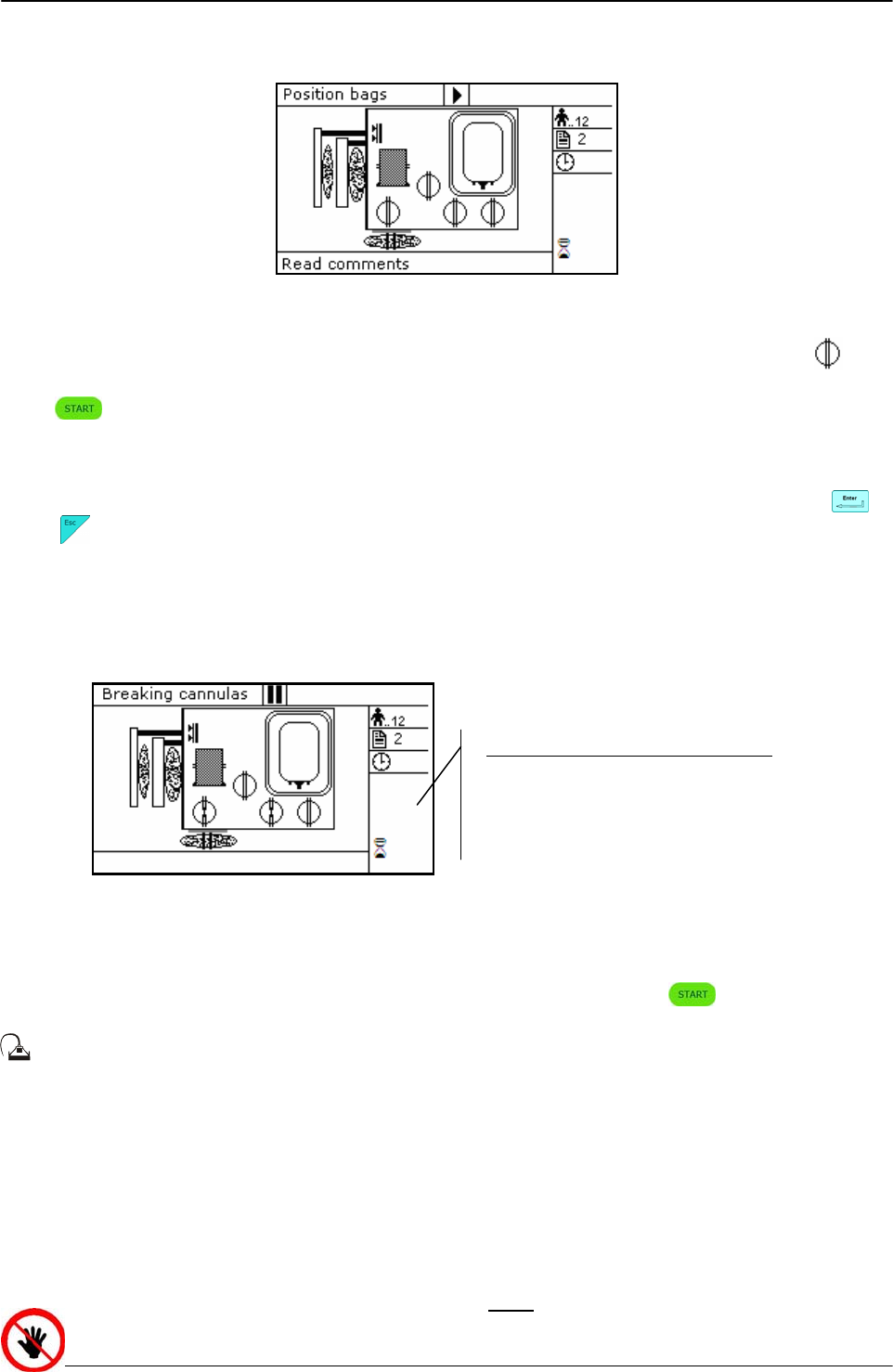
Picture 37: T/T quadruple bags in position
Archimede checks correct tubes positioning inside proper clamps by mens of its optical
sensors. The tube is correctly inserted when the clamp number is replaced by the icon .
Press key-button to start the procedure.
If the primary bag expected weight check has been enabled through ArchimedeLINK and the
detected weight does not fall within the set limits, a warning will be displayed showing both
limits and current weight. After verifying the cause of the problem, confirm weight with or
press to leave the procedure. Furthermore, if the tube presence check is enabled the
display will show the clamp numbers where tubes are not correctly inserted and the procedure
will not start until all tubes are correctly inserted into the enabled clapms
Now wait for the plate to get close to the bag. The plate will exert a force corresponding to the
value set in the procedure parameters.
Picture 38: Break cannulas view quadruple T/T procedure
Break the cannulas by forcing on their side upper part. Wait for a few seconds that positive
pressure is released. After detecting pressure decrease, Archimede automatically starts the
separation cycle. If pressure does not decrease below the set value, due to tube obstruction or
fluid clogging, it is anyway possible to force the cycle start by pressing keybutton.
During the procedure, possible comments can be read on the external part of the fix
front plate.
The graphic interface will now show the current operating phase number, and the weight value
of plasma collected. Archimede will check the erythrocytes level in the primary bag. When this
level reaches the selected IR sensor, the display will show it in the area of the RBC-pressing
plate; the plasma line will be closed and the buffy coat line will be opened. When the buffy
coat amount reaches the value set in the relevant procedure parameter, the system will enable
the mechanical separation group and let the set plasma (PPP) amount flow to clean the line.
When cleaning is over, buffy coat will be dispensed in the bag, and the plate will move back
words to allow Sag. M. dispensing.
ATTENTION: THE FORCE SENSOR IS ENABLED ONLY WHEN THE PLATE MOVES TOWARDS THE
INSTRUMENT BODY.
Parameters of the ongoing phase:
#8: RBC action threshold
#22 Buffy coat amount
#19: Excess plasma for filter
USING ARCHIMEDE
Page 42 of 105 User Manual Revision 1.05
CAUTION: DO NOT PUT YOUR HANDS IN THE PLATE WORKING AREA WHEN THE PLATE IS MOVING.
If air elimination is enabled, the system will send the air contanied in the primary bag to the
Sag. M. bag both at initial and final stage.
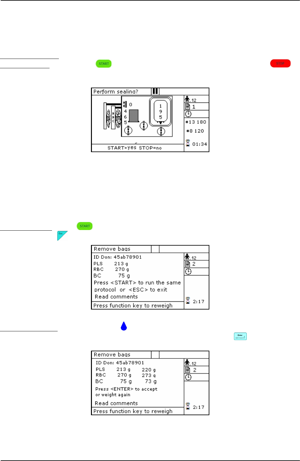
The sealing cycle depends on the value set in the procedure parameters:
Automatic sealing: sealing cycle of the selected clamps is performed automatically.
Manual sealing: press keybutton to seal the enabled lines, or press to
continue, after confirming, without sealing.
Picture 39: Sealing procedure T/T quadrupla
Archimede will automatically send to ArchimedeLINK all events and data of the procedure
performed.
At the end of the procedure the display will show the detected weights. If they are not the
expected ones, because tubes are not correctly placed and distort scales’ readings, the
emocomponents can be weighed again after correcting tubes’ position and the new weights
can be sent to ArchimedeLINK again.
Correct weights: press keybutton to continue with the same type of separation or press
to go back to the page listing the procedures.
Picture 40: Viewing weights T / T quadruple.
Incorrect weights: press one of the keybuttons to weigh emocomponents again. To accept
the new values and send them to ArchimedeLINK press
Picture 41: T/T quadruple with weight out of normal range.
USING ARCHIMEDE
User Manual Revision 1.05 Page 43 of 105
With ArchimedeLINK the normal limits check can be activated. If it is enabled and the detected
weights do not fall within the set limits, the display will show the emocomponents’ detected
weights and the allowed limits. Press any key to continue.
Picture 42: T/T quadruple with weight out of normal range
Now remove tubes and bags and press to continue with another separation of the same
type or press to exit.
If you need to interrupt the procedure either momentarily or definitively, press
keybutton.
Picture 43: Pause or Stop procedure T/T quadruple
Stop: press or . Archimede will display the sealing page and send data to
ArchimedeLINK.
Pause: press or to continue the procedure.

USING ARCHIMEDE
Page 44 of 105 User Manual Revision 1.05
4.6.4 PROCEDURE 3 Top & Bottom triple PPP+BC+RCC.
This procedure is indicated for triple top & bottom bags to obtain buffy coat (BC), erythrocytes
(RCC) and plasma (PRP).
Parameters used:
1 During the procedure, checks that tubes are properly inserted into the clamps enabled for
the ongoing procedure.
2 Enables the routine controlling breaking of the primary bag cannulas.
3 Force in xx.x Kg beyond which the plate stops and waits for cannulas breaking.
4 Plate forward moving speed during cannulas breaking step.
5 Value used to calculate the force value below which the systems exits the cannulas
breaking routine. V =(force measured at breaking position) – (current force).
7 Value minimal of difference of reading between RBC and plasma with which it comes
controlled the bag before and during the procedure
8 Sensibility HB sensor.
9 Value of the maximum force applied during the procedure; the plate stops if the force
exceeds this limit.
11 Selection of the sealing mode. In automatic mode, the system automatically seals the
bags when the procedure is over. In manual mode, bags sealing must be confirmed.
12 Selection of clamps to be used for sealing when the procedure is over. Clamps are
numbered as follows: 1 Top, 2 Plasma, 4 Buffy, 8 Bottom. The value to be set in this
position is the value corresponding to the sum of the clamps used: for example, if bottom
and top are to be used, the value to be set is 9.
13 Plate moving speed used in the first phase for the management of force
15 Number identifying the IR sensor dedicated to buffy coat level.
18 Buffy coat target value.
20 Sag. M. amount [g] to be dispensed in the final step of the procedure.
21 Sag.M. amount already present in RBC destination bag.
25 Tare of the primary bag. This value is used to calculate the product amount left in the
primary bag. [current weight - tare].
32 Sensibility flow valve. (Clamp 6)
36 Plasma amount to be dispensed in the buffy coat bag.
40 Value allowing to select the clamps to be used in the procedure.
41 Number of the profile plate to be used with the ongoing procedure.
42 Enables the air elimination routine.
43 Primary bag positioning with blade ready for weighing.
44 Scale stability check.
45 Check Correlation Distance Weight.
46 Enable scale reading.
47 IR corresponding to upper and lower bag edges.
USING ARCHIMEDE
User Manual Revision 1.05 Page 45 of 105
Position bags and tubes according to the below sequence. Be sure to avoid tensions and folds
that might cause flow obstruction or weighing errors.
Picture 44: Kit installation T/B triple procedure.
NOTE: Tubes in the various kits have different lengths. To simplify kits management, the
firmware allows to configure which valves you wish to enable.
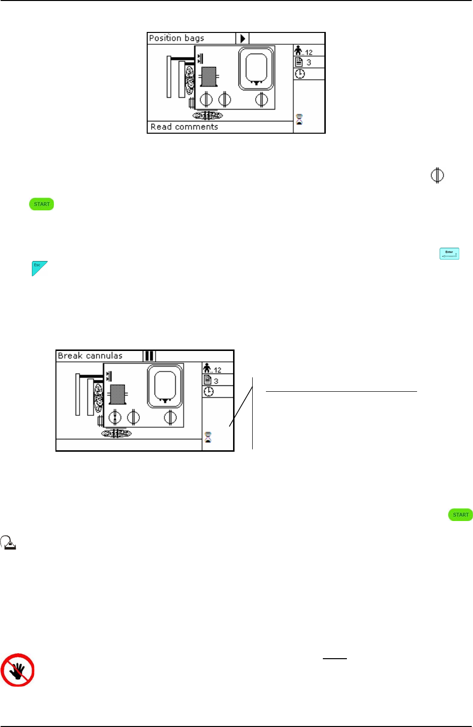
Picture 45: Position primary T/B triple bag.
Hang the primary bag to the bag holders on the front panel. The label containing bag data
should always be turned outside. After detecting the primary bag, the plate will move
backword to make positioning of Sag.M. bag easier, and the display will show the bag icon.
Picture 46: Position plasma, buffy coat and Sag.M. T/T triple bags.
If required, hang the Sag. M. bag to the bag holders on the fix plate and insert the Sag. M.
tube into clamp 5.
Open cover of HB sensor and insert the tube coming from the primary bag into the reading
area. Close the cover.
Insert the plasma tube firmly into the flow-valve.
Insert the tube coming from the flow-valve firmly into clamp 3.
Insert RBC tube into clamp 4.
Position the plasma bag on upper scale.
Primary bag
Scale 1
Sa
g
. M. ba
g
Scale 2
Scale 3
Clam
p
3
Clam
p
6
Clam
p
4
HB sensor
USING ARCHIMEDE
Page 46 of 105 User Manual Revision 1.05
Position the RBC bag on lateral scale.
Picture 47: T/B triple bags in position.
Archimede checks correct tubes positioning inside proper clamps by mens of its optical
sensors. The tube is correctly inserted when the clamp number is replaced by the icon .
Press key-button to start the procedure.
If the primary bag expected weight check has been enabled through ArchimedeLINK and the
detected weight does not fall within the set limits, a warning will be displayed showing both
limits and current weight. After verifying the cause of the problem, confirm weight with or
press to leave the procedure. Furthermore, if the tube presence check is enabled the
display will show the clamp numbers where tubes are not correctly inserted and the procedure
will not start until all tubes are correctly inserted into the enabled clapms
Now wait for the plate to get close to the bag. The plate will exert a force corresponding to the
value set in the procedure parameters.
Picture 48: Break cannulas view T/B triple procedure.
Brake the cannulas by forcing on the side upper part of the cannula. Wait for a few seconds
that positive pressure is released. After detecting pressure decrease, Archimede automatically
starts the separation cycle. If pressure does not decrease below the set value, due to tube
obstruction or fluid clogging, it is anywayt possible to force the cycle start by pressing
keybutton.
During the procedure, possible comments can be read on the external part of the fix
front plate.
The graphic interface will now show the current operating phase number, and the weight value
of plasma collected. Archimede will check the buffy coat level through IR sensors, flow valve
and valves 3 and 4. The distance sensor will stop the separation process when the plate
reaches the distance set in the procedure parameters. When this process is over, the plate will
move back words to allow Sag. M. dispensing if required.
ATTENTION: THE FORCE SENSOR IS ENABLED ONLY WHEN THE PLATE MOVES
TOWARDS THE INSTRUMENT BODY.
CAUTION: DO NOT PUT YOUR HANDS IN THE PLATE WORKING AREA WHEN THE
PLATE IS MOVING.
Parameters of the ongoing phase:
#18: B.C target
#8: RBC action threshold
#20: Sag. M. amount
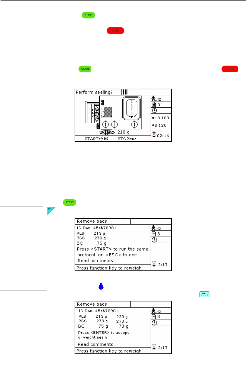
USING ARCHIMEDE
User Manual Revision 1.05 Page 47 of 105
Air elimination depends on procedure parameters setting:
Manual air elimination: press keybutton to open clamp 3, put plasma bag in vertical
position and remove air manually by pressing on the bag. When
finished, press keybutton to close clamp 3, and re-position
plasma bag to detect weight.
The sealing cycle depends on the value set in the procedure parameters:
Automatic sealing: sealing cycle of the selected clamps is performed automatically.
Manual sealing: press keybutton to seal the enabled lines, or press to
continue, after confirming, without sealing.
Picture 49: Sealing procedure T/B tripe
Archimede will automatically send to ArchimedeLINK all events and data of the procedure
performed.
At the end of the procedure the display will show the detected weights. If they are not the
expected ones, because tubes are not correctly placed and distort scales’ readings, the
emocomponents can be weighed again after correcting tubes’ position and the new weights
can be sent to ArchimedeLINK again.
Correct weights: press keybutton to continue with the same type of separation or press
to go back to the page listing the procedures.
Picture 50: Viewing weights T / B triple.
Incorrect weights: press one of the keybuttons to weigh emocomponents again. To accept
the new values and send them to ArchimedeLINK press keybutton.
Picture 51: Reweigh T/B triple
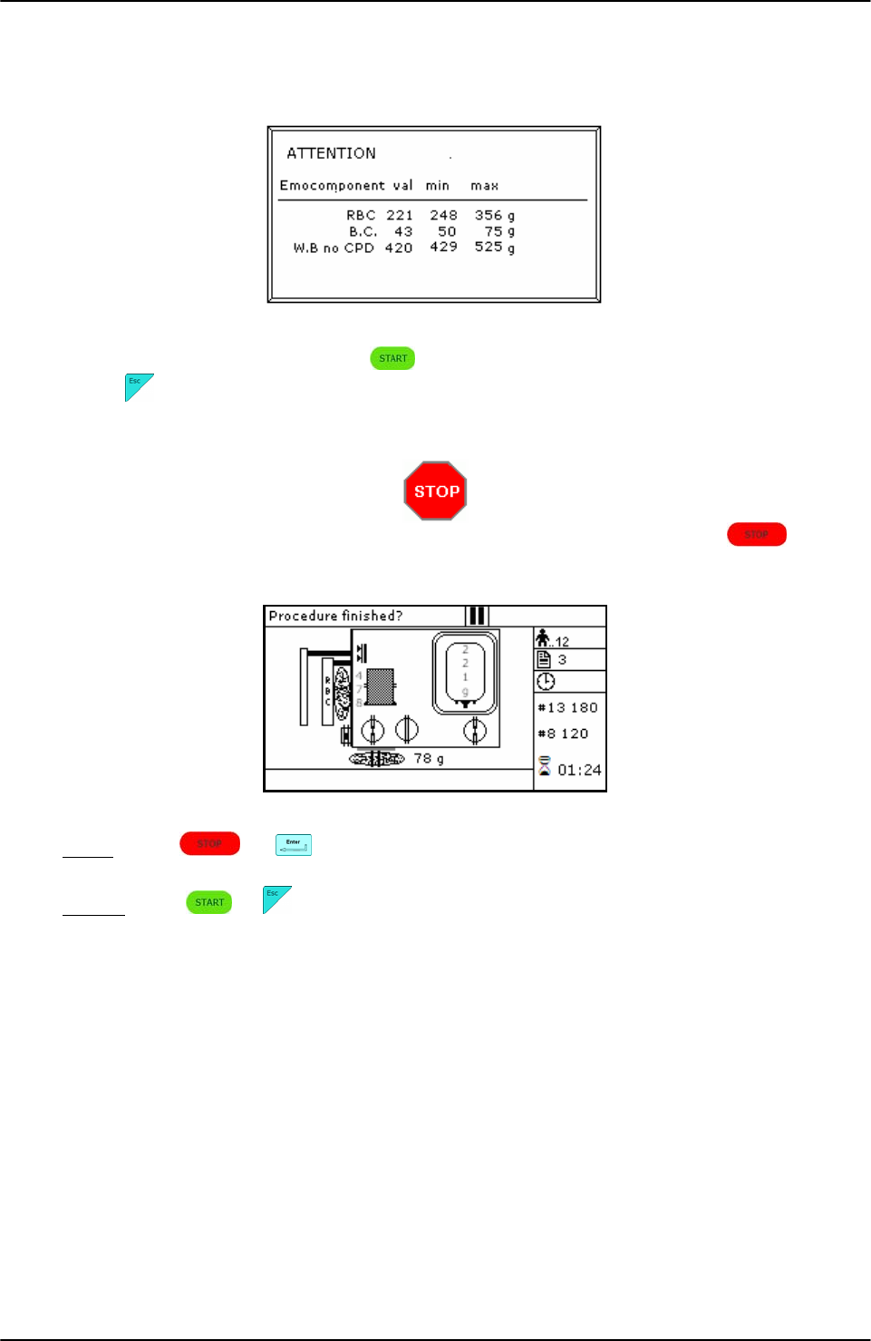
USING ARCHIMEDE
Page 48 of 105 User Manual Revision 1.05
With ArchimedeLINK the normal limits check can be activated. If it is enabled and the detected
weights do not fall within the set limits, the display will show the emocomponents’ detected
weights and the allowed limits. Press any key to continue.
Picture 52: T/B triple with weight out of normal range.
Now remove tubes and bags and press to continue with another separation of the same
type or press to exit.
If you need to interrupt the procedure either momentarily or definitively, press
keybutton.
Picture 53: Pause or Stop procedure T/B triple
Stop: press or . Archimede will display the sealing page and send data to
ArchimedeLINK.
Pause: press or to continue the procedure.

USING ARCHIMEDE
User Manual Revision 1.05 Page 49 of 105
4.6.5 PROCEDURE 4 Top & Bottom quadruple PPP+BC+RCC.
This procedure is indicated for quadruple top & bottom bags to obtain buffy coat (BC),
erythrocytes (RCC) and two plasma (PPP) one PPP for single buffy coat.
Parameters used:
1 During the procedure, checks that tubes are properly inserted into the clamps enabled for
the ongoing procedure.
2 Enables the routine controlling breaking of the primary bag cannulas.
3 Force in xx.x Kg beyond which the plate stops and waits for cannulas breaking.
4 Plate forward moving speed during cannulas breaking step.
5 Value used to calculate the force value below which the systems exits the cannulas
breaking routine. V =(force measured at breaking position) – (current force).
7 Value minimal of difference of reading between RBC and plasma with which it comes
controlled the bag before and during the procedure
8 Sensibility HB sensor.
9 Value of the maximum force applied during the procedure; the plate stops if the force
exceeds this limit.
11 Selection of the sealing mode. In automatic mode, the system automatically seals the
bags when the procedure is over. In manual mode, bags sealing must be confirmed.
12 Selection of clamps to be used for sealing when the procedure is over. Clamps are
numbered as follows: 1 Top, 2 Plasma, 4 Buffy, 8 Bottom. The value to be set in this
position is the value corresponding to the sum of the clamps used: for example, if bottom
and top are to be used, the value to be set is 9.
13 Plate moving speed used in the first phase for the management of force.
15 Number identifying the IR sensor dedicated to buffy coat level.
18 Buffy coat target value.
20 Sag. M. amount [g] to be dispensed in the final step of procedure.
21 Sag.M. amount already present in RBC destination bag.
25 Tare of the primary bag. This value is used to calculate the product amount left in the
primary bag [current weight - tare].
32 Flow valve sensibility. (Clamp 6)
34 Plasma amount to be added to second plasma bag.
36 Plasma amount to be dispensed by gravity in the buffy coat bag.
40 Value allowing to select the clamps to be used in the procedure.
41 Number of the profile plate to be used with the ongoing procedure.
42 Enables the air elimination routine.
43 Primary bag positioning with blade ready for weighing.
44 Scale stability check.
45 Check Correlation Distance Weight.
46 Enable scale reading.
47 IR corresponding to upper and lower bag edges.
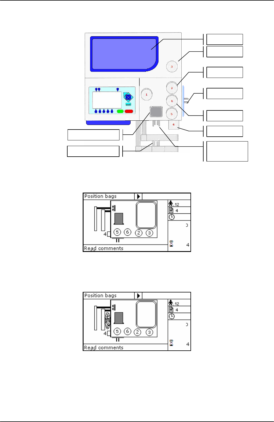
USING ARCHIMEDE
Page 50 of 105 User Manual Revision 1.05
Position bags and tubes according to the below sequence. Be sure to avoid tensions and folds
that might cause flow obstruction or weighing errors.
Picture 54: Kit installation T/B quadruple procedure
NOTE: Tubes in the various kits have different lengths. To simplify kits management, the
firmware allows to configure which valves you wish to enable.
Picture 55: Position primary T/B quadrupla bag.
Hang the primary bag to the bag holders on the front panel. The label containing bag data
should always be turned outside. After detecting the primary bag, the plate will move
backword to make positioning of Sag.M. bag easier, and the display will show the bag icon.
Picture 56: Position plasma, buffy coat and Sag.M. T/B quadruple bags.
If required, hang the Sag. M. bag to the bag holders on the fix plate and insert the Sag. M.
tube into clamp 5.
Open cover of HB sensor and insert the tube coming from the primary bag into the reading
area. Close the cover.
Insert the plasma tube firmly into the flow-valve. (clamp 6)
Insert the plasma tube coming from the flow-valve firmly into clamp 3.
Position the plasma bag on upper scale.
Insert the secondary plasma bag tube into clamp 2.
Primary bag
Scale 1
Sa
g
. M. ba
g
Scale 2
Scale 3
Clam
p
1
Clam
p
6
Clam
p
4
HB sensor
Clam
p
2
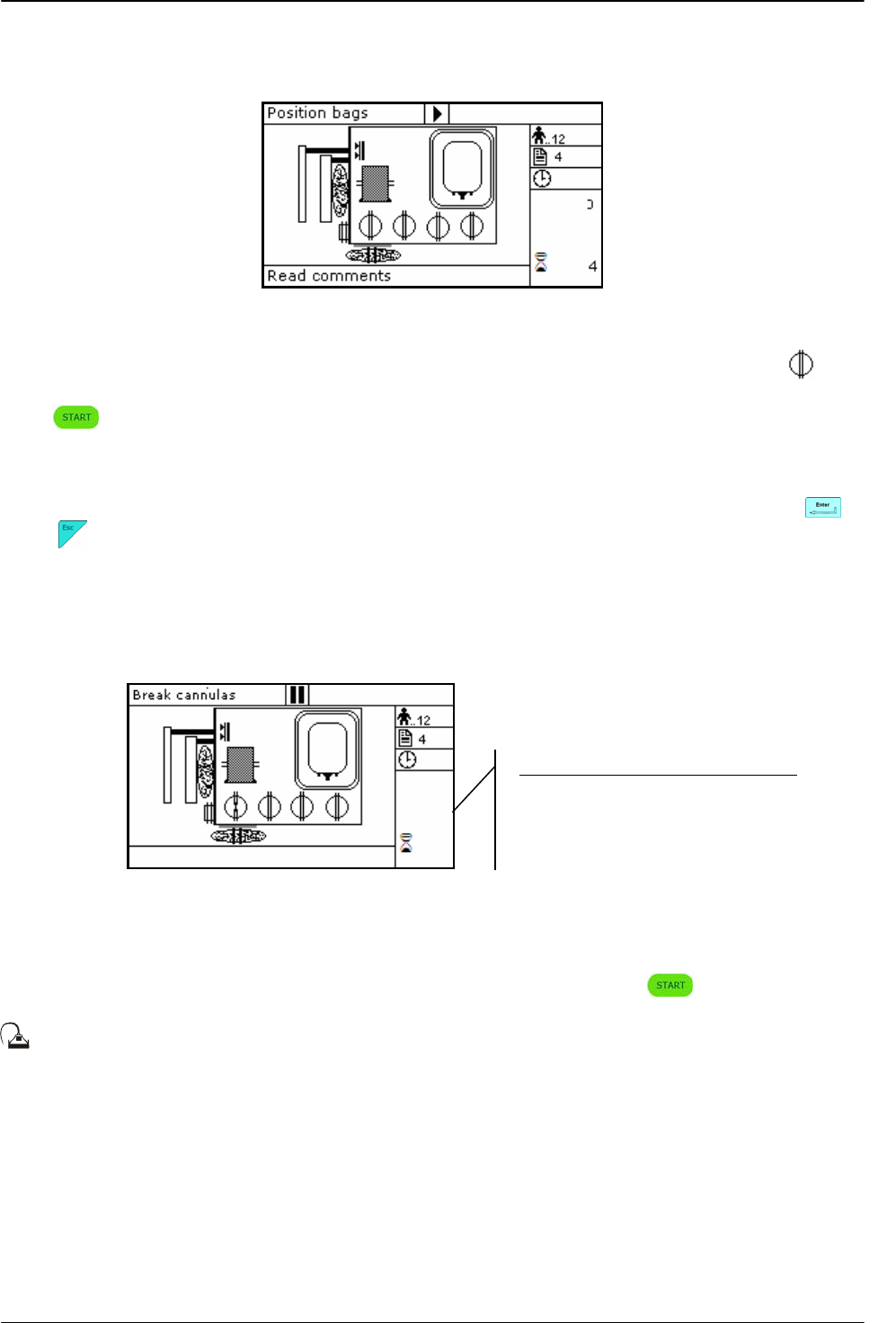
USING ARCHIMEDE
User Manual Revision 1.05 Page 51 of 105
Position the secondary plasma bag on upper scale.
Insert RBC tube into clamp 4.
Position the RBC bag on lateral scale.
Picture 57: T/B quadruple bags in position.
Archimede checks correct tubes positioning inside proper clamps by mens of its optical
sensors. The tube is correctly inserted when the clamp number is replaced by the icon .
Press key-button to start the procedure.
If the primary bag expected weight check has been enabled through ArchimedeLINK and the
detected weight does not fall within the set limits, a warning will be displayed showing both
limits and current weight. After verifying the cause of the problem, confirm weight with or
press to leave the procedure. Furthermore, if the tube presence check is enabled the
display will show the clamp numbers where tubes are not correctly inserted and the procedure
will not start until all tubes are correctly inserted into the enabled clapms
Now wait for the plate to get close to the bag. The plate will exert a force corresponding to the
value set in the procedure parameters.
Picture 58: Break cannulas view T/B quadruple procedure.
Break the cannulas by forcing on their side upper part. Wait for a few seconds that positive
pressure is released. After detecting pressure decrease, Archimede automatically starts the
separation cycle. If pressure does not decrease below the set value, due to tube obstruction or
fluid clogging, it is anyway possible to force the cycle start by pressing keybutton.
During the procedure, possible comments can be read on the external part of the fix
front plate.
The graphic interface will now show the current operating phase number, and the weight value
of plasma collected. Archimede will check the buffy coat level through IR sensors, flow valve
and valves 2, 3 and 4. The distance sensor will stop the separation process when the plate
reaches the distance set in the procedure parameters. When this process is over, the plate will
move back words to allow Sag. M. dispensing if required.
Parameters of the ongoing phase:
#18: B.C. target
#8: RBC action threshold
#20: Sag. M. amount
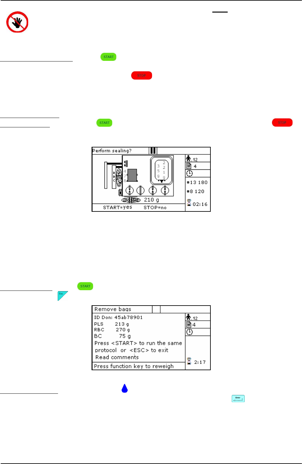
USING ARCHIMEDE
Page 52 of 105 User Manual Revision 1.05
ATTENTION: THE FORCE SENSOR IS ENABLED ONLY WHEN THE PLATE MOVES
TOWARDS THE INSTRUMENT BODY.
CAUTION: DO NOT PUT YOUR HANDS IN THE PLATE WORKING AREA WHEN THE
PLATE IS MOVING.
Air elimination depends on procedure parameters setting:
Manual air elimination: press keybutton to open clamp 3, put plasma bag in vertical
position and remove air manually by pressing on the bag. When
finished, press keybutton to close clamp 3, and re-position
plasma bag to detect weight.
The sealing cycle depends on the value set in the procedure parameters:
Automatic sealing: sealing cycle of the selected clamps is performed automatically.
Manual sealing: press keybutton to seal the enabled lines, or press to
continue, after confirming, without sealing.
Picture 59: Sealing Procedure T/B quadruple
Archimede will automatically send to ArchimedeLINK all events and data of the procedure
performed.
At the end of the procedure the display will show the detected weights. If they are not the
expected ones, because tubes are not correctly placed and distort scales’ readings, the
emocomponents can be weighed again after correcting tubes’ position and the new weights
can be sent to ArchimedeLINK again.
Correct weights: press keybutton to continue with the same type of separation or press
to go back to the page listing the procedures.
Picture 60: Viewing weight T/B quadruple
Incorrect weights: press one of the keybuttons to weigh emocomponents again. To accept
the new values and snd them to ArchimedeLINK press
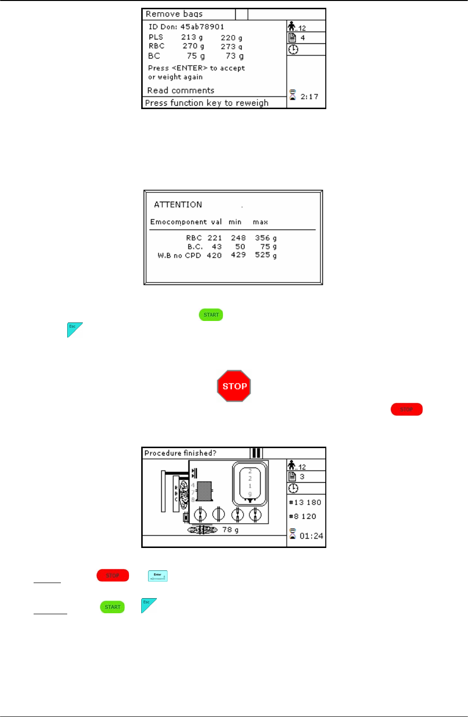
USING ARCHIMEDE
User Manual Revision 1.05 Page 53 of 105
Picture 61: Reweight T/B quadruple
With ArchimedeLINK the normal limits check can be activated. If it is enabled and the detected
weights do not fall within the set limits, the display will show the emocomponents’ detected
weights and the allowed limits. Press any key to continue.
Picture 62: T/B quadruple with weight out of normal range.
Now remove tubes and bags and press to continue with another separation of the same
type or press to exit.
If you need to interrupt the procedure either momentarily or definitively, press
keybutton.
Picture 63: Pause or Stop procedure T/B quadruple.
Stop: press or . Archimede will display the sealing page and send data to
ArchimedeLINK.
Pause: press or to continue the procedure.

USING ARCHIMEDE
Page 54 of 105 User Manual Revision 1.05
4.6.6 PROCEDURE 5 Separation from PRP to PPP+PLT
This secondary procedure is for separate from PRP to result platelets poor plasma (PPP), and
platelets concentrate.
Parameters used:
1 During the procedure, checks that tubes are properly inserted into the clamps enabled for
the ongoing procedure.
2 Enables the routine controlling breaking of the primary bag cannulas.
3 Force in xx.x Kg beyond which the plate stops and waits for cannulas breaking.
4 Plate forward moving speed during cannulas breaking step.
5 Value used to calculate the force value below which the systems exits the cannulas
breaking routine. V =(force measured at breaking position) – (current force).
9 Value of the maximum force applied during the procedure; the plate stops if the force
exceeds this limit.
11 Selection of the sealing mode. In automatic mode, the system automatically seals the
bags when the procedure is over. In manual mode, bags sealing must be confirmed.
12 Selection of clamps to be used for sealing when the procedure is over. Clamps are
numbered as follows: 1 Top, 2 Plasma, 4 Buffy, 8 Bottom. The value to be set in this
position is the value corresponding to the sum of the clamps used: for example, if bottom
and top are to be used, the value to be set is 9.
13 Plate moving speed used in the first phase for the management of force.
18 Value of the final distance beyond which the procedure stops.
25 Tare of primary bag. This value is used to calculate the product amount left in the primary
bag [current weight - tare].
30 Plasma-plt weight.
40 Value allowing to select the clamps to be used in the procedure
41 Number of the profile plate to be used with the ongoing procedure.
42 Enables the air elimination routine.
43 Primary bag positioning with blade ready for weighing.
44 Scale stability check.
45 Check Correlation Distance Weight.
46 Enable scale reading.
47 IR coresponding to upper and lower bag edge.
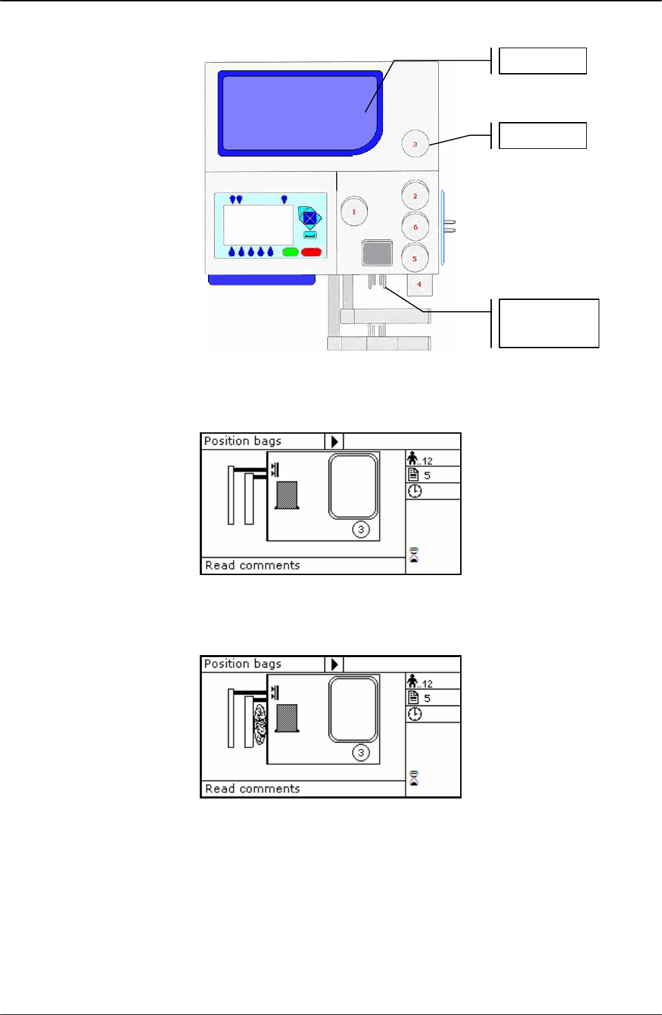
USING ARCHIMEDE
User Manual Revision 1.05 Page 55 of 105
Position bags and tubes according to the below sequence. Be sure to avoid tensions and folds
that might cause flow obstruction or weighing errors.
Picture 64: Kit installation procedure PRP to PPP+PLT
NOTE: Tubes in the various kits have different lengths. To simplify kits management, the
firmware allows to configure which valves you wish to enable.
Picture 65: Position primary bag procedure PRP to PPP + PRP
Hang the primary bag to the bag holders on the front panel. The label containing bag data
should always be turned outside.
Picture 66: Position PLT bag procedure PRP to PPP + PRP.
• Open HB sensor cover and put the tube coming from primary bag inside the reading area.
Close cover.
Insert the plasma tube firmly into clamp 3.
Position the plasma bag on upper scale.
Primari bag
Scale 1
Clam
p
3
Scale 2
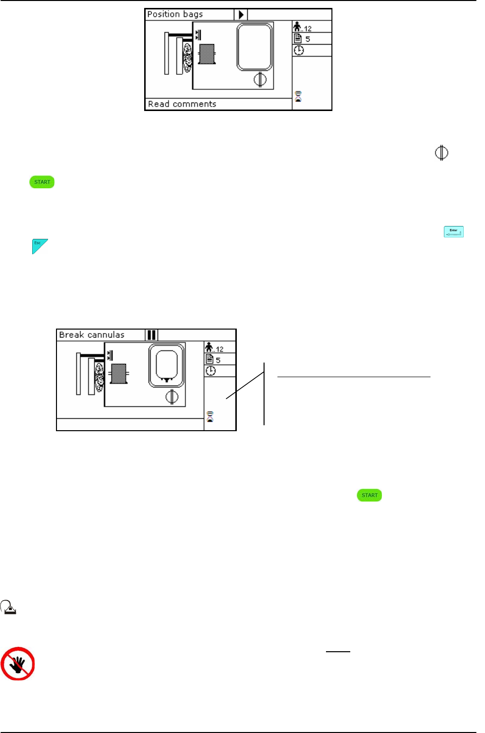
USING ARCHIMEDE
Page 56 of 105 User Manual Revision 1.05
Picture 67: PRP to PPP + PRP bags in position.
Archimede checks correct tubes positioning inside proper clamps by mens of its optical
sensors. The tube is correctly inserted when the clamp number is replaced by the icon .
Press key-button to start the procedure.
If the primary bag expected weight check has been enabled through ArchimedeLINK and the
detected weight does not fall within the set limits, a warning will be displayed showing both
limits and current weight. After verifying the cause of the problem, confirm weight with or
press to leave the procedure. Furthermore, if the tube presence check is enabled the
display will show the clamp numbers where tubes are not correctly inserted and the procedure
will not start until all tubes are correctly inserted into the enabled clapms
Now wait for the plate to get close to the bag. The plate will exert a force corresponding to the
value set in the procedure parameters.
Picture 68: Break cannulas view procedure PRP to PPP + PRP
Break the cannulas by forcing on their side upper part. Wait for a few seconds that positive
pressure is released. After detecting pressure decrease, Archimede automatically starts the
separation cycle. If pressure does not decrease below the set value, due to tube obstruction or
fluid clogging, it is anyway possible to force the cycle start by pressing keybutton.
The graphic interface will now show the current operating phase number, and the weight value
of plasma collected. The operating phase depends on the distance set in the procedure
parameters.
Archimede will check the plate distance. The distance sensor will stop the separation process
when the plate reaches the distance set in the procedure parameters, and the plate will move
back words to standby position.
During the procedure, possible comments can be read on the external part of the fix
front plate.
ATTENTION: THE FORCE SENSOR IS ENABLED ONLY WHEN THE PLATE MOVES
TOWARDS THE INSTRUMENT BODY.
CAUTION: DO NOT PUT YOUR HANDS IN THE PLATE WORKING AREA WHEN THE
PLATE IS MOVING.
Parameters of the ongoing phase:
#18: Action distance between phases
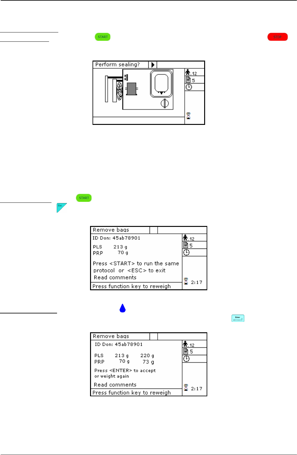
USING ARCHIMEDE
User Manual Revision 1.05 Page 57 of 105
The sealing cycle depends on the value set in the procedure parameters:
Automatic sealing: sealing cycle of the selected clamps is performed automatically.
Manual sealing: press keybutton to seal the enabled lines, or press to
continue, after confirming, without sealing.
Picture 69: Sealing procedure PRP to PPP + PRP
Archimede will automatically send to ArchimedeLINK all events and data of the procedure
performed.
At the end of the procedure the display will show the detected weights. If they are not the
expected ones, because tubes are not correctly placed and distort scales’ readings, the
emocomponents can be weighed again after correcting tubes’ position and the new weights
can be sent to ArchimedeLINK again.
Correct weights: press keybutton to continue with the same type of separation or press
to go back to the page listing the procedures.
Picture 70: Viewing weight PRP to PPP + PRP.
Incorrect weights: press one of the keybuttons to weigh emocomponents again. To accept
the new values and send them to ArchimedeLINK press
Picture 71: Reweight procedure PRP to PPP + PRP.
With ArchimedeLINK the normal limits check can be activated. If it is enabled and the detected
weights do not fall within the set limits, the display will show the emocomponents’ detected
weights and the allowed limits. Press any key to continue.
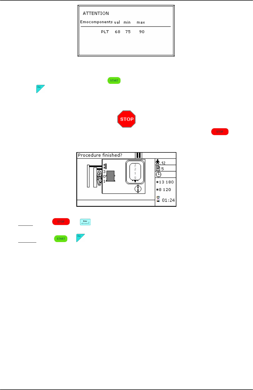
USING ARCHIMEDE
Page 58 of 105 User Manual Revision 1.05
Picture 72: Procedure PRP to PPP + PRP with weight out of normal range..
Now remove tubes and bags and press to continue with another separation of the same
type or press to exit.
If you need to interrupt the procedure either momentarily or definitively, press
keybutton.
Picture 73: Pause or Stop procedure PRP to PPP + PRP.
Stop: press or . Archimede will display the sealing page and send data to
ArchimedeLINK.
Pause: press or to continue the procedure.

USING ARCHIMEDE
User Manual Revision 1.05 Page 59 of 105
4.6.7 PROCEDURE 7 Single or Pool of Buffy for PLT + residual BC with filter
This procedure allows to collect platelets and filtrate.
Parameters used:
1 During the procedure, checks that tubes are properly inserted into the clamps enabled for
the ongoing procedure.
2 Enables the routine controlling breaking of the primary bag cannulas.
3 Force in xx.x Kg beyond which the plate stops and waits for cannulas breaking.
4 Plate forward moving speed during cannulas breaking step.
5 Value used to calculate the force value below which the systems exits the cannulas
breaking routine. V =(force measured at breaking position) – (current force).
6 Number identifying the IR sensor dedicated to RBC sensor enabling.
8 Sensibility HB sensor.
9 Value of the maximum force applied during the procedure; the plate stops if the force
exceeds this limit.
10 Threshold value for action of IR sensors.
11 Selection of the sealing mode. In automatic mode, the system automatically seals the
bags when the procedure is over. In manual mode, bags sealing must be confirmed.
12 Selection of clamps to be used for sealing when the procedure is over. Clamps are
numbered as follows: 1 Top, 2 Plasma, 4 Buffy, 8 Bottom. The value to be set in this
position is the value corresponding to the sum of the clamps used: for example, if bottom
and top are to be used, the value to be set is 9.
13 Plate moving speed used in the first phase for the management of force.
18 Value of the distance beyond which the system, after confirmation, stops the procedure if
no RBCs have been detected.
19 Excess plasma [g] to be dispensed after the HB sensor has detected RBCs. If manual
dispensing is enabled, the system allows manual product dispensing.
24 Motor speed during filter priming.
25 Tare of the primary bag. This value is used to calculate the product amount left in the
primary bag [current weight - tare]
38 Minimum flow that should pass through the filter. Below this value an alarm of obstructed
filter is activated.
40 Value allowing to select the clamps to be used in the procedure.
41 Number of the profile plate to be used with the ongoing procedure.
42 Enables the air elimination routine.
43 Primary bag positioning with blade ready for weighing.
44 Scale stability check.
45 Check Correlation Distance Weight.
46 Enable scale reading.
47 IR corresponding to upper and lower bag edge.
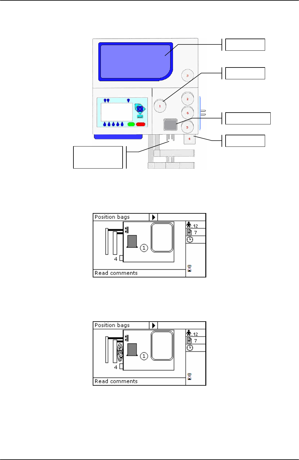
USING ARCHIMEDE
Page 60 of 105 User Manual Revision 1.05
Position bags and tubes according to the below sequence. Be sure to avoid tensions and folds
that might cause flow obstruction or weighing errors.
Picture 74: Kit installation procedure PLT with filter
NOTE: Tubes in the various kits have different lengths. To simplify kits management, the
firmware allows to configure which valves you wish to enable.
Picture 75: Position primary bag separation PLT with filter.
Hang the primary bag to the bag holders on the front panel. The label containing bag data
should always be turned outside.
Picture 76: Position PLT bag separation PLT with filter.
Insert the tube coming from the primary bag into clamp 4.
Open cover of HB sensor and insert the tube coming from filter into the reading area. Close
the cover.
Insert the tube coming from the HB sensor firmly into clamp 1.
Position the PLT bag on upper scale.
Primary bag
Scale 1
HB Sensor
Scale 2
Clam
p
1
Clam
p
4
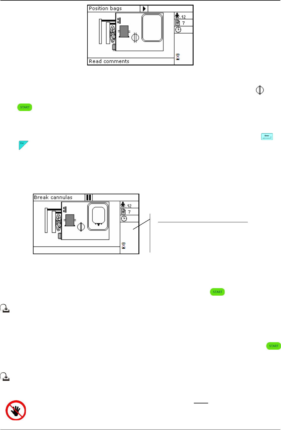
USING ARCHIMEDE
User Manual Revision 1.05 Page 61 of 105
Picture 77: Bag PLT with filter in position.
Archimede checks correct tubes positioning inside proper clamps by mens of its optical
sensors. The tube is correctly inserted when the clamp number is replaced by the icon .
Press key-button to start the procedure.
If the primary bag expected weight check has been enabled through ArchimedeLINK and the
detected weight does not fall within the set limits, a warning will be displayed showing both
limits and current weight. After verifying the cause of the problem, confirm weight with or
press to leave the procedure. Furthermore, if the tube presence check is enabled the
display will show the clamp numbers where tubes are not correctly inserted and the procedure
will not start until all tubes are correctly inserted into the enabled clapms
Now wait for the plate to get close to the bag. The plate will exert a force corresp0onding to
the value set in the procedure parameters.
Picture 78: Break cannulas view procedure PLT with filter.
Break the cannulas by forcing on their side upper part. Wait for a few seconds that positive
pressure is released. After detecting pressure decrease, Archimede automatically starts the
separation cycle. If pressure does not decrease below the set value, due to tube obstruction or
fluid clogging, it is anyway possible to force the cycle start by pressing keybutton.
During the procedure, possible comments can be read on the external part of the fix
front plate.
The graphic interface will now show the current operating phase number, and the weight value
of PLT collected. Archimede will check the flow and stop the plate in case of filter obstruction
or RBC presence in the HB sensor. In case of filter obstruction, the operator can press
and continue until the new warning, while in case of RBC presence the system will stop the
collection process and move the plate back to home position.
During the procedure, possible comments can be read on the external part of the fix
front plate.
ATTENTION: THE FORCE SENSOR IS ENABLED ONLY WHEN THE PLATE MOVES
TOWARDS THE INSTRUMENT BODY.
CAUTION: DO NOT PUT YOUR HANDS IN THE PLATE WORKING AREA WHEN THE
PLATE IS MOVING.
Parameters of the ongoing phase:
#13: Plate forward moving speed
#18: Action distance between phases
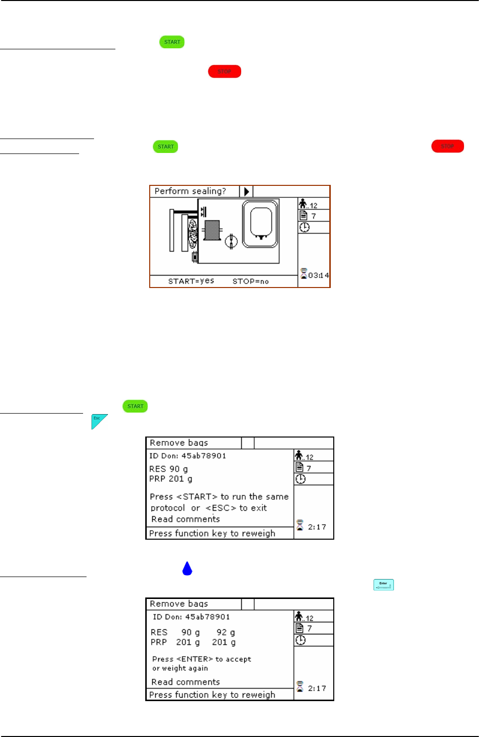
USING ARCHIMEDE
Page 62 of 105 User Manual Revision 1.05
Air elimination depends on procedure parameters setting:
Manual air elimination: press keybutton to open clamp 3, put plasma bag in vertical
position and remove air manually by pressing on the bag. When
finished, press keybutton to close clamp 3, and re-position
plasma bag to detect weight.
The sealing cycle depends on the value set in the procedure parameters:
Automatic sealing: sealing cycle of the selected clamps is performed automatically.
Manual sealing: press keybutton to seal the enabled lines, or press to
continue, after confirming, without sealing.
Picture 79: Sealing procedure PLT with filter.
Archimede will automatically send to ArchimedeLINK all events and data of the procedure
performed.
At the end of the procedure the display will show the detected weights. If they are not the
expected ones, because tubes are not correctly placed and distort scales’ readings, the
emocomponents can be weighed again after correcting tubes’ position and the new weights
can be sent to ArchimedeLINK again.
Correct weights: press keybutton to continue with the same type of separation or press
to go back to the page listing the procedures.
Picture 80: Viewing weight PLT with filter.
Incorrect weight: press one of the keybuttons to weigh emocomponents again. To accept
the new values and send them to ArchimedeLINK press
Picture 81: Reweight procedure PLT with filter.
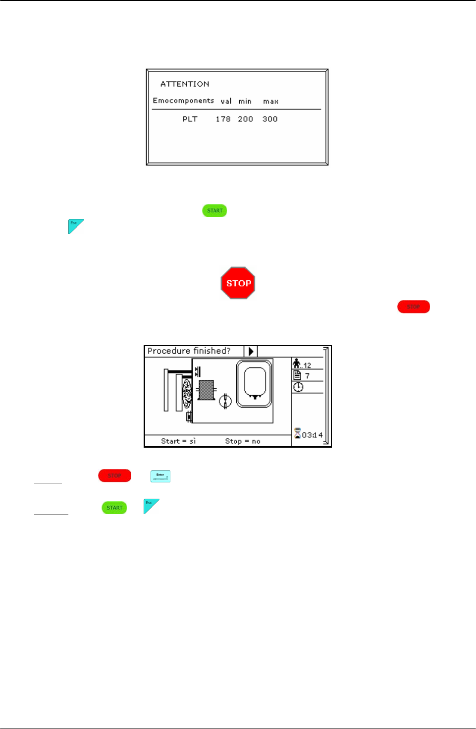
USING ARCHIMEDE
User Manual Revision 1.05 Page 63 of 105
With ArchimedeLINK the normal limits check can be activated. If it is enabled and the detected
weights do not fall within the set limits, the display will show the emocomponents’ detected
weights and the allowed limits. Press any key to continue.
Picture 82: Procedure PLT with filter with weight out of normal range.
Now remove tubes and bags and press to continue with another separation of the same
type or press to exit.
If you need to interrupt the procedure either momentarily or definitively, press
keybutton.
Picture 83: Pause or Stop procedure PLT with filter.
Stop: press or . Archimede will display the sealing page and send data to
ArchimedeLINK.
Pause: press or to continue the procedure.

USING ARCHIMEDE
Page 64 of 105 User Manual Revision 1.05
4.6.8 PROCEDURA 8 Separation of Erythrocytes Washing
This procedure allows to separate the washing fluid from erythrocytes subjected to a washing
procedure.
Parameters used:
1 During the procedure, checks that tubes are properly inserted into the clamps enabled for
the ongoing procedure.
2 Enables the routine controlling breaking of the primary bag cannulas.
3 Force in xx.x Kg beyond which the plate stops and waits for cannulas breaking.
4 Plate forward moving speed during cannulas breaking step.
5 Value used to calculate the force value below which the systems exits the cannulas
breaking routine. V =(force measured at breaking position) – (current force).
6 Number identifying the IR sensor dedicated to RBC sensor enabling.
7 Value minimal of difference of reading between RBC and plasma with which it comes
controlled the bag before and during the procedure
8 Sensibility HB sensor.
9 Value of the maximum force applied during the procedure; the plate stops if the force
exceeds this limit.
11 Selection of the sealing mode. In automatic mode, the system automatically seals the
bags when the procedure is over. In manual mode, bags sealing must be confirmed.
12 Selection of clamps to be used for sealing when the procedure is over. Clamps are
numbered as follows: 1 Top, 2 Plasma, 4 Buffy, 8 Bottom. The value to be set in this
position is the value corresponding to the sum of the clamps used: for example, if bottom
and top are to be used, the value to be set is 9.
13 Plate moving speed used in the first phase for the management of force.
18 Value of the distance beyond which the system, after confirmation, stops the procedure if
no RBCs have been detected.
40 Value allowing to select the clamps to be used in the procedure.
41 Number of the profile plate to be used with the ongoing procedure.
43 Primary bag positioning with blade ready for weighing.
44 Scale stability check.
45 Check Correlation Distance Weight.
46 Enable scale reading.
47 IR corresponding to upper and lower bag edges.
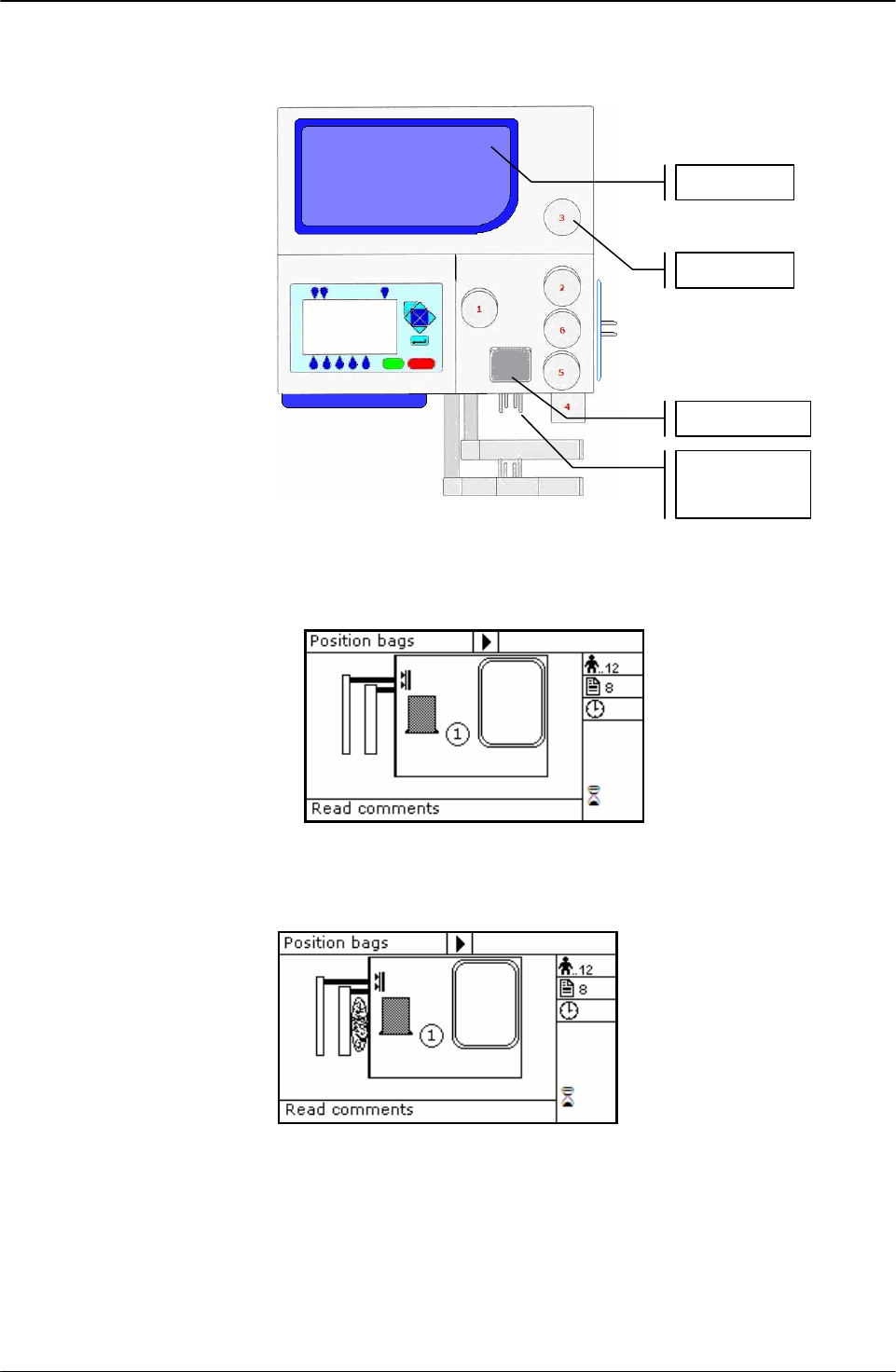
USING ARCHIMEDE
User Manual Revision 1.05 Page 65 of 105
Position bags and tubes according to the below sequence. Be sure to avoid tensions and folds
that might cause flow obstruction or weighing errors.
Picture 84: Kit installation procedure erythrocytes washing.
NOTE: Tubes in the various kits have different lengths. To simplify kits management, the
firmware allows to configure which valves you wish to enable.
Picture 85: Position primary bag erythrocytes washing.
Hang the primary bag to the bag holders on the front panel. The label containing bag data
should always be turned outside.
Picture 86: Position erythrocytes washing bag.
Open cover of HB sensor and insert the tube coming from the primary bag into the reading
area. Close the cover.
Insert the tube coming from the HB sensor firmly into clamp 1.
Position the washing fluid bag on upper scale.
Primari bag
Scale 1
HB Sensor
Clam
p
3
Scale 2
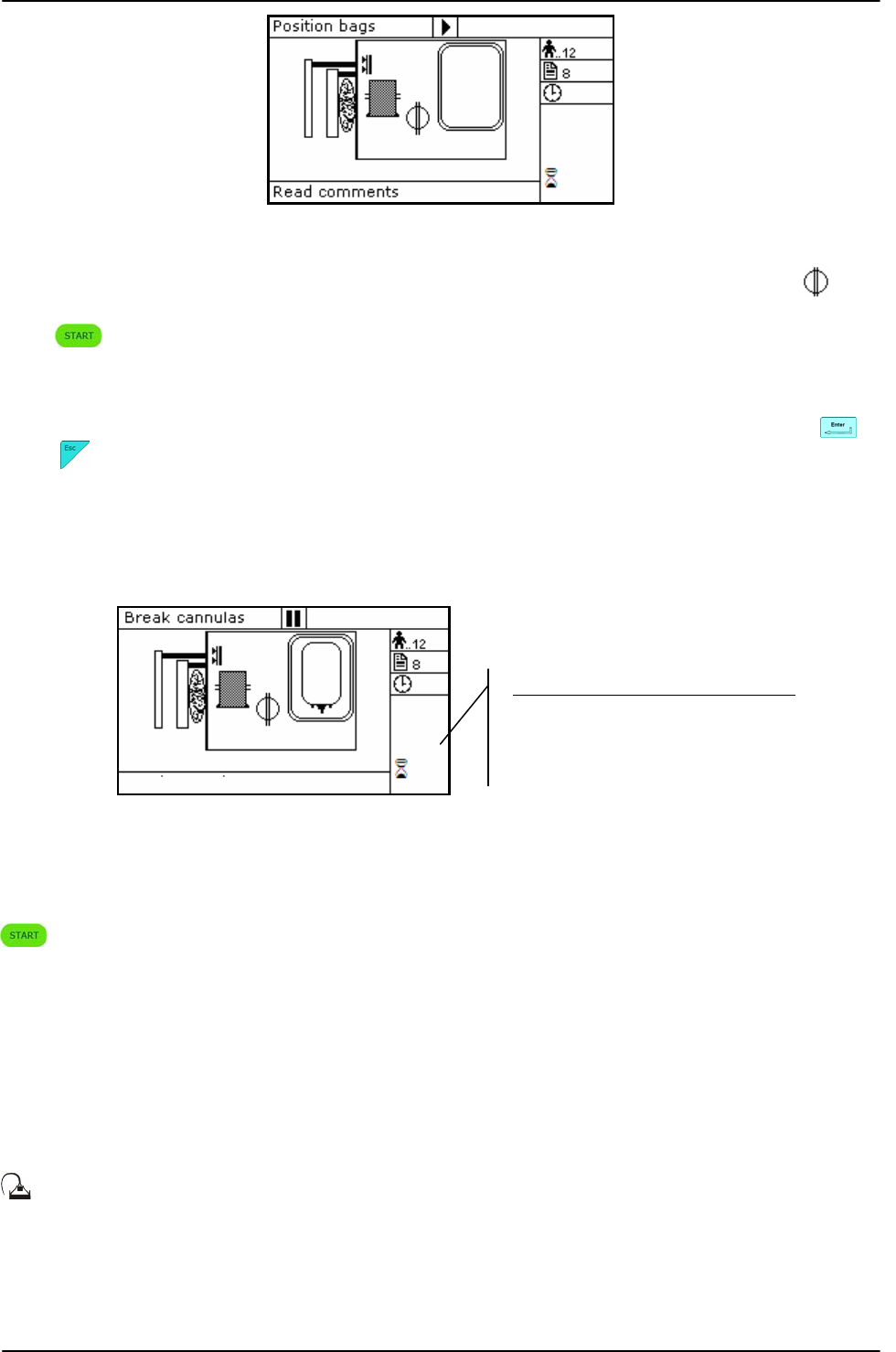
USING ARCHIMEDE
Page 66 of 105 User Manual Revision 1.05
Picture 87: Erythrocytes washing bag in position.
Archimede checks correct tubes positioning inside proper clamps by mens of its optical
sensors. The tube is correctly inserted when the clamp number is replaced by the icon .
Press key-button to start the procedure.
If the primary bag expected weight check has been enabled through ArchimedeLINK and the
detected weight does not fall within the set limits, a warning will be displayed showing both
limits and current weight. After verifying the cause of the problem, confirm weight with or
press to leave the procedure. Furthermore, if the tube presence check is enabled the
display will show the clamp numbers where tubes are not correctly inserted and the procedure
will not start until all tubes are correctly inserted into the enabled clapms
Now wait for the plate to get close to the bag. The plate will exert a force corresponding to the
value set in the procedure
Picture 88: Break cannulas view erythrocytes washing procedure
Break the cannulas by forcing on the side upper part of the cannula itself. Wait for a few
seconds that positive pressure is released. After detecting pressure decrease, Archimede
automatically starts the separation cycle. If pressure does not decrease below the set value,
due to tube obstruction or fluid clogging, it is anyway possible to force the cycle by pressing
keybutton.
The graphic interface will now show the current operating phase number, and the washing
solution weight collected. Archimede will check the erythrocytes level in the primary bag.
When this level reaches the selected IR sensor, the display will show “RBC” in the pressing
plate area.
The photometer detecting the presence of erythrocytes will now check, in real time, the
washing liquid flow. When the erythrocytes amount exceeds the value set in procedure
parameters, the photometry will display “RBC” on the sensor cover icon, the relative valve will
stop, and the plate will move backwards to standby position.
During the procedure, possible comments can be read on the external part of the fix
front plate.
Parameters of the ongoing phase:
#13: Plate forward moving speed
#18: Action distance between phases
#8: RBC action threshold
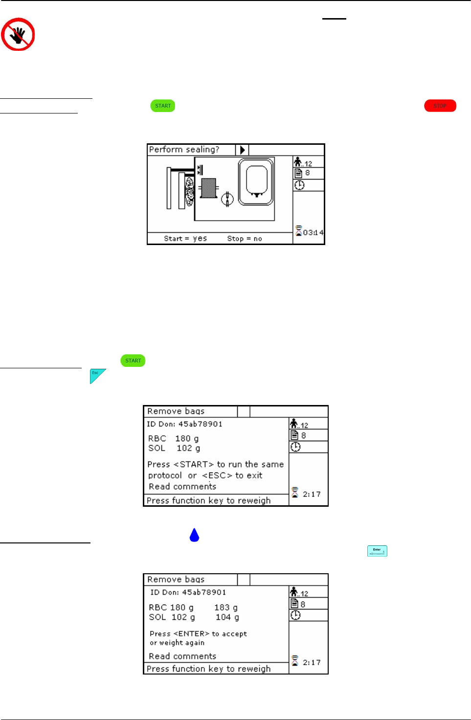
USING ARCHIMEDE
User Manual Revision 1.05 Page 67 of 105
ATTENTION: THE FORCE SENSOR IS ENABLED ONLY WHEN THE PLATE MOVES
TOWARDS THE INSTRUMENT BODY.
CAUTION: DO NOT PUT YOUR HANDS IN THE PLATE WORKING AREA WHEN THE
PLATE IS MOVING.
The sealing cycle depends on the value set in the procedure parameters:
Automatic sealing: sealing cycle of the selected clamps is performed automatically.
Manual sealing: press keybutton to seal the enabled lines, or press to
continue, after confirming, without sealing.
Picture 89: Sealing erythrocytes washing procedure.
Archimede will automatically send to ArchimedeLINK all events and data of the procedure
performed.
At the end of the procedure the display will show the detected weights. If they are not the
expected ones, because tubes are not correctly placed and distort scales’ readings, the
emocomponents can be weighed again after correcting tubes’ position and the new weights
can be sent to ArchimedeLINK again.
Correct weights: press keybutton to continue with the same type of separation or press
to go back to the page listing the procedures.
Picture 90: Viewing weight erythrocytes washing .
Incorrect weights: press one of the keybuttons to weigh emocomponents again. To accept
the new values and send them to ArchimedeLINK press
Picture 91: Reweight procedure erythrocytes washing.
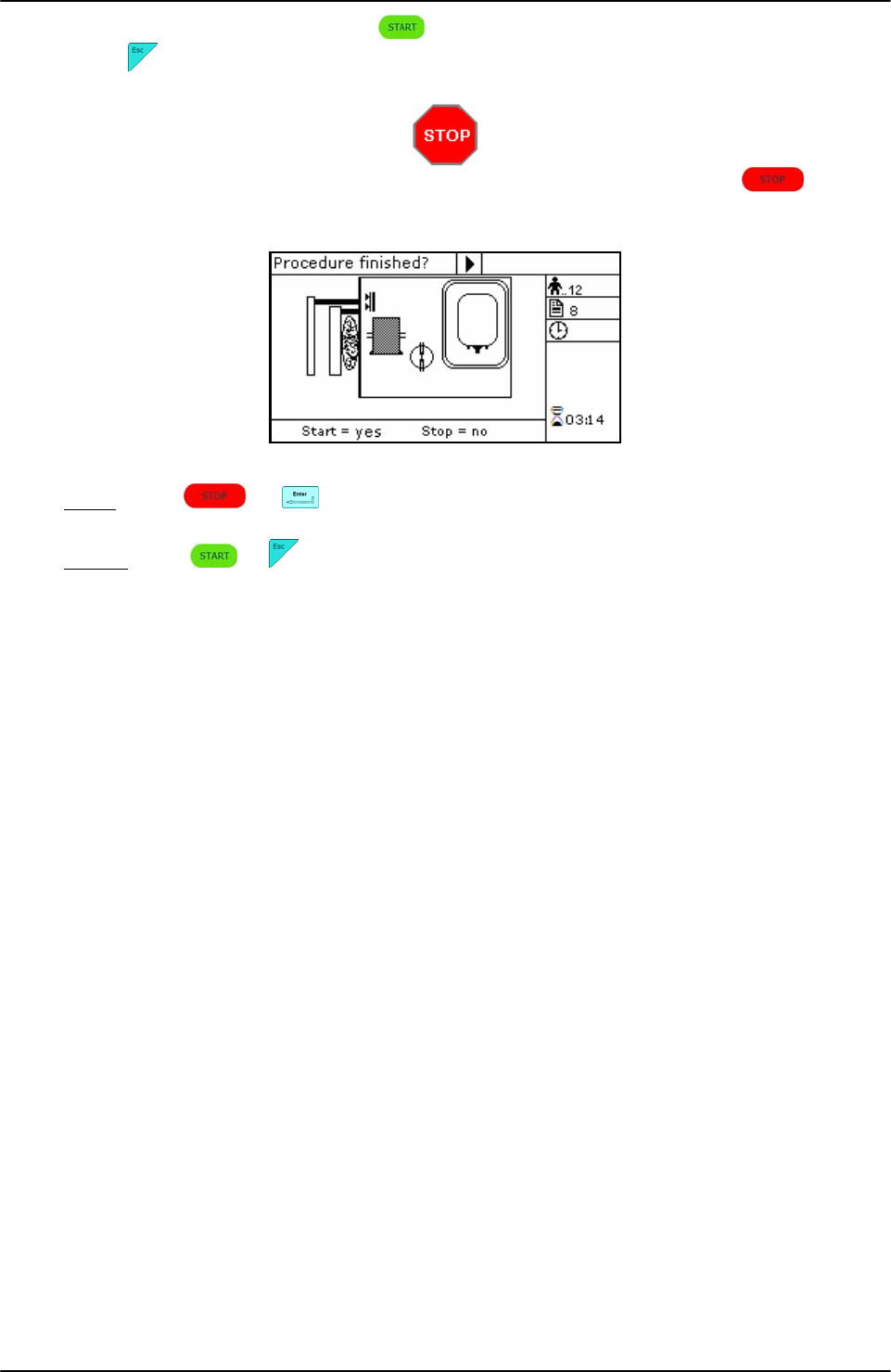
USING ARCHIMEDE
Page 68 of 105 User Manual Revision 1.05
Now remove tubes and bags and press to continue with another separation of the same
type or press to exit.
If you need to interrupt the procedure either momentarily of definitively, press
keybutton.
Picture 92: Pause or Stop in procedure erythrocytes washing .
Stop: press or . Archimede will display the sealing page and send data to
ArchimedeLINK.
Pause: press or to continue the procedure.

USING ARCHIMEDE
User Manual Revision 1.05 Page 69 of 105
4.6.9 PROCEDURE 10 [a]UMBILICAL CORD
This procedure is indicated for quadruple top & bottom bag to obtain erythrocytes (RCC),
plasma (PPP), and buffy coat (BC) diluted with plasma added through a press.
Parameters used:
1 During the procedure, checks that tubes are properly inserted into the clamps enabled for
the ongoing procedure.
2 Enables the routine controlling breaking of the primary bag cannulas.
3 Force in xx.x Kg beyond which the plate stops and waits for cannulas breaking.
4 Plate forward moving speed during cannulas breaking step.
5 Value used to calculate the force value below which the systems exits the cannulas
breaking routine. V =(force measured at breaking position) – (current force).
7 Value minimal of difference of reading between RBC and plasma with which it comes
controlled the bag before and during the procedure.
8 Sensibility HB sensor.
9 Value of the maximum force applied during the procedure; the plate stops if the force
exceeds this limit.
11 Selection of the sealing mode. In automatic mode, the system automatically seals the
bags when the procedure is over. In manual mode, bags sealing must be confirmed.
12 Selection of clamps to be used for sealing when the procedure is over. Clamps are
numbered as follows: 1 Top, 2 Plasma, 4 Buffy, 8 Bottom. The value to be set in this
position is the value corresponding to the sum of the clamps used: for example, if bottom
and top are to be used, the value to be set is 9.
13 Plate moving speed used in the first phase for the management of force.
15 Number identifying the IR sensor dedicated to buffy coat level.
18 Buffy coat target value.
25 Tare of the primary bag. This value is used to calculate the product amount left in the
primary bag [current weight - tare]
32 Sensibility flow valve. (Clamp 6)
40 Value allowing to select the clamps to be used in the procedure.
41 Number of the profile plate to be used with the ongoing procedure.
42 Enables the air elimination routine.
43 Primary bag positioning with blade ready for weighing.
44 Scale stability check.
45 Check Correlation Distance Weight.
46 Enable scale reading.
47 IR corresponding to upper and lower bag edges.
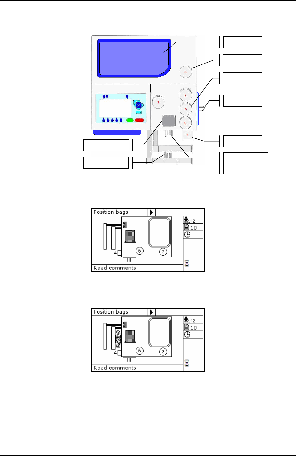
USING ARCHIMEDE
Page 70 of 105 User Manual Revision 1.05
Position bags and tubes according to the below sequence. Be sure to avoid tensions and folds
that might cause flow obstruction or weighing errors.
Picture 93: Kit installation procedure umbilical cord
NOTE: Tubes in the various kits have different lengths. To simplify kits management, the
firmware allows to configure which valves you wish to enable.
Picture 94: Position primary bag umbilical cord procedure.
Hang the primary bag to the bag holders on the front panel. The label containing bag data
should always be turned outside.
Picture 95: Position plasma, RBC bag of umbilical cord procedure.
Open cover of HB sensor and insert the tube coming from the primary bag into the reading
area. Close the cover.
Insert the tube coming from HB sensor into clamp 6.
Insert the tube coming from clamp 6 into clamp 3.
Position the plasma bag on upper scale.
Insert bottom tube into clamp 4.
Position the RBC bag on lateral scale.
Primary bag
Scale 1
Sa
g
. M. ba
g
Scale 2
Scale 3
Clam
p
1
Clam
p
6
Clam
p
4
HB sensor
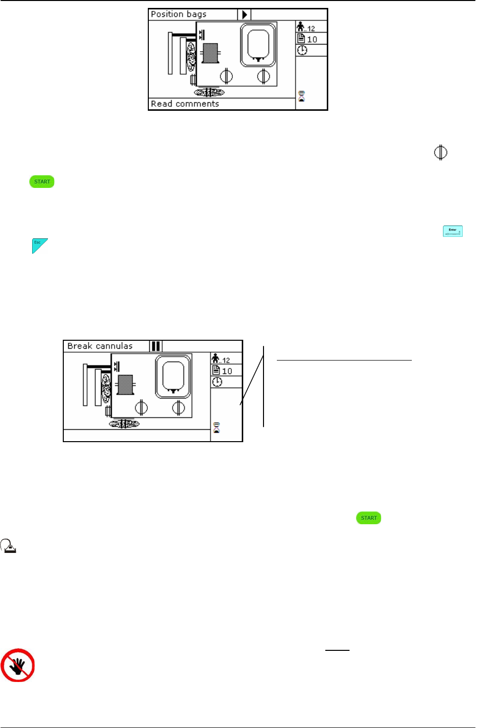
USING ARCHIMEDE
User Manual Revision 1.05 Page 71 of 105
Picture 96: Erythrocytes umbilical cord in position.
Archimede checks correct tubes positioning inside proper clamps by mens of its optical
sensors. The tube is correctly inserted when the clamp number is replaced by the icon .
Press key-button to start the procedure.
If the primary bag expected weight check has been enabled through ArchimedeLINK and the
detected weight does not fall within the set limits, a warning will be displayed showing both
limits and current weight. After verifying the cause of the problem, confirm weight with or
press to leave the procedure. Furthermore, if the tube presence check is enabled the
display will show the clamp numbers where tubes are not correctly inserted and the procedure
will not start until all tubes are correctly inserted into the enabled clapms
Now wait for the plate to get close to the bag. The plate will exert a force corresponding to the
value set in the procedure parameters.
Picture 97: Break cannulas view umbilical cord procedure.
Break the cannulas by forcing on their side upper part. Wait for a few seconds that positive
pressure is released. After detecting pressure decrease, Archimede automatically starts the
separation cycle. If pressure does not decrease below the set value, due to tube obstruction or
fluid clogging, it is anyway possible to force the cycle start by pressing keybutton.
During the procedure, possible comments can be read on the external part of the fix
front plate.
The graphic interface will now show the current operating phase number, and the weight value
of plasma collected. Archimede will check the buffy coat level through IR sensors, flow valve
and valves 3, and 4. The distance sensor will stop the separation process when the plate
reaches the distance set in the procedure parameters.
ATTENTION: THE FORCE SENSOR IS ENABLED ONLY WHEN THE PLATE MOVES
TOWARDS THE INSTRUMENT BODY.
CAUTION: DO NOT PUT YOUR HANDS IN THE PLATE WORKING AREA WHEN THE
PLATE IS MOVING.
The sealing cycle depends on the value set in the procedure parameters:
Parameters of ongoing phase:
#13: Plate forward moving speed
#18: Action distance between phases
#8: RBC action threshold
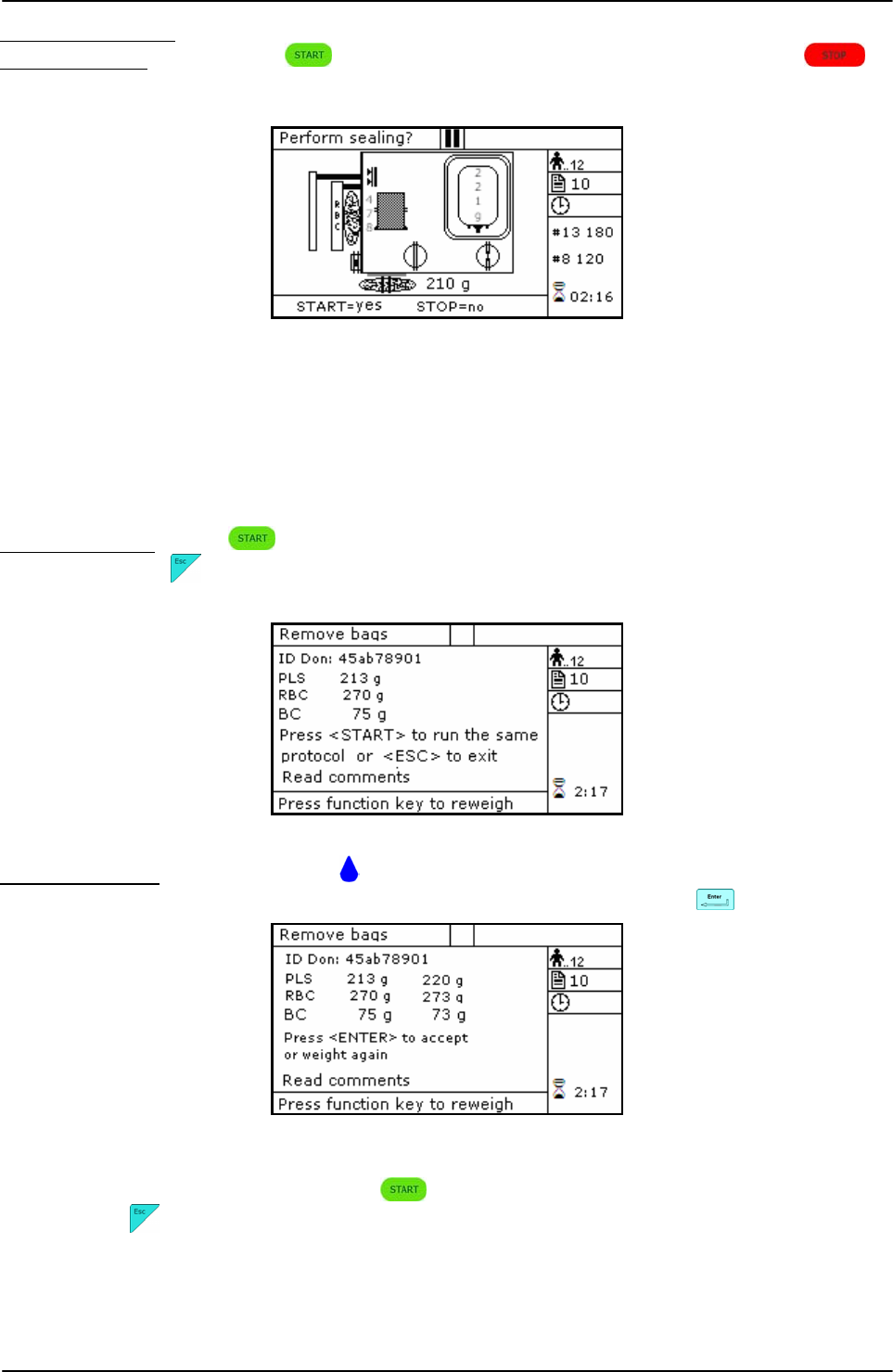
USING ARCHIMEDE
Page 72 of 105 User Manual Revision 1.05
Automatic sealing: sealing cycle of the selected clamps is performed automatically.
Manual sealing: press keybutton to seal the enabled lines, or press to
continue, after confirming, without sealing.
Picture 98: Sealing umbilical cord procedure.
Archimede will automatically send to ArchimedeLINK all events and data of the procedure
performed.
At the end of the procedure the display will show the detected weights. If they are not the
expected ones, because tubes are not correctly placed and distort scales’ readings, the
emocomponents can be weighed again after correcting tubes’ position and the new weights
can be sent to ArchimedeLINK again.
Correct weights: press keybutton to continue with the same type of separation or press
to go back to the page listing the procedures.
Picture 99: Viewing weight umbilical cord procedure
Incorrect weiths: press one of the keybuttons to weigh emocomponents again. To accept
the new values and send them to ArchimedeLINK press .
Picture 100: Reweight umbilical cord procedure.
Now remove tubes and bags and press to continue with another separation of the same
type or press to exit.
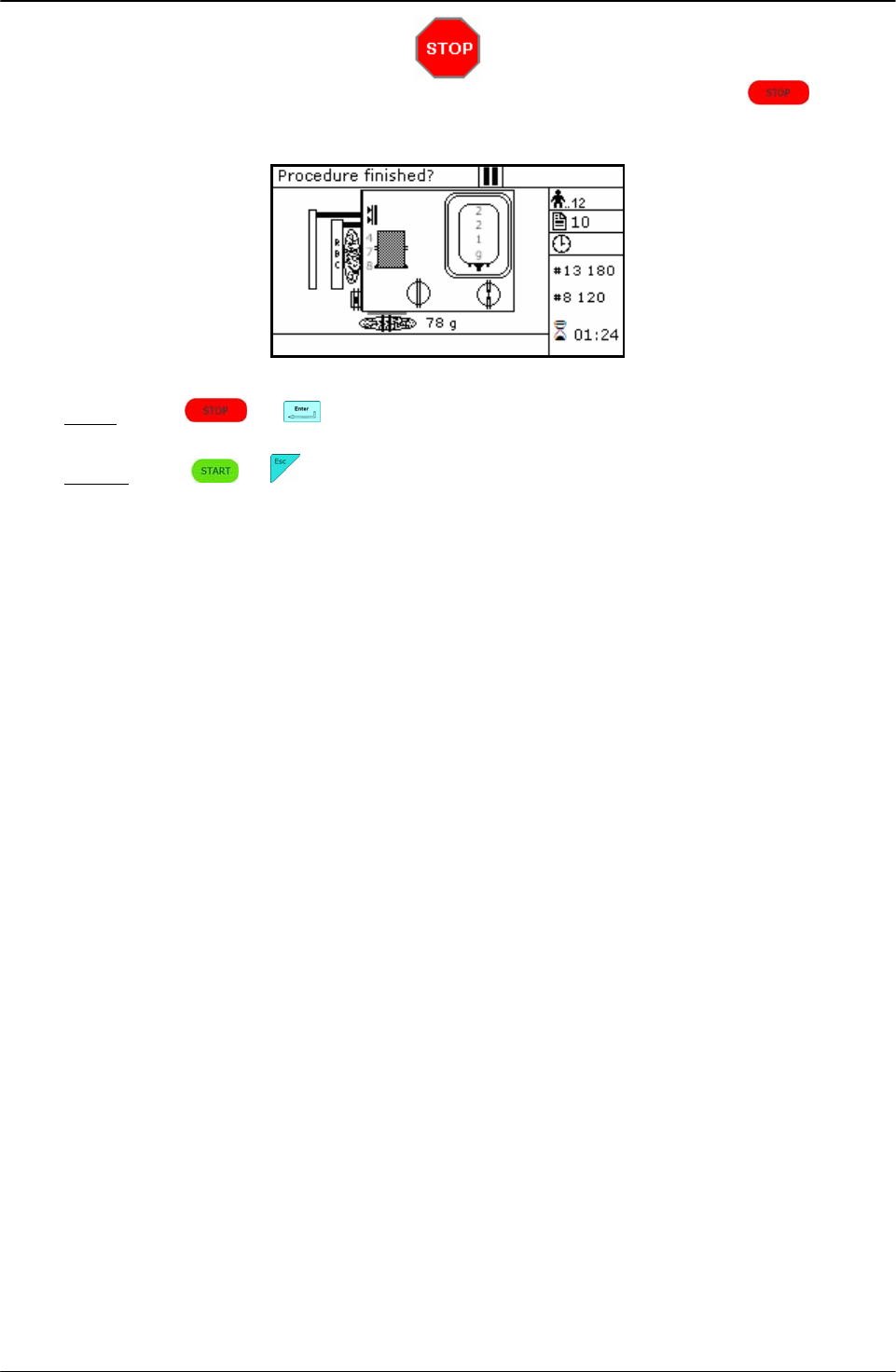
USING ARCHIMEDE
User Manual Revision 1.05 Page 73 of 105
If you need to interrupt the procedure either momentarily or definitively, press
keybutton.
Picture 101: Pause or Stop procedure umbilical cord.
Stop: press or . Archimede will display the sealing page and send data to
ArchimedeLINK.
Pause: press or to continue the procedure.

USING ARCHIMEDE
Page 74 of 105 User Manual Revision 1.05
4.6.10 PROCEDURE 11 [b] ALIQUOT SEPARATION
This procedure allows to separate emocomponents in the four available bags by weighing them
separately.
Parameters used:
1 During the procedure, checks that tubes are properly inserted into the clamps enabled for
the ongoing procedure.
2 Enables the routine controlling breaking of the primary bag cannulas.
3 Force in xx.x Kg beyond which the plate stops and waits for cannulas breaking.
4 Plate forward moving speed during cannulas breaking step.
5 Value used to calculate the force value below which the systems exits the cannulas
breaking routine. V =(force measured at breaking position) – (current force).
9 Value of the maximum force applied during the procedure; the plate stops if the force
exceeds this limit.
11 Selection of the sealing mode. In automatic mode, the system automatically seals the
bags when the procedure is over. In manual mode, bags sealing must be confirmed.
12 Selection of clamps to be used for sealing when the procedure is over. Clamps are
numbered as follows: 1 Top, 2 Plasma, 4 Buffy, 8 Bottom. The value to be set in this
position is the value corresponding to the sum of the clamps used: for example, if bottom
and top are to be used, the value to be set is 9.
13 Plate moving speed used in the first phase for the management of force.
14 Weight of aliquot 2. (Upper scale)
18 Value of the distance beyond which the system, after confirmation, stops the procedure if
the set volumes have not been dispensed.
25 Tare of the primary bag. This value is used to calculate the product amount left in the
primary bag [current weight - tare].
29 Weight of aliquot 1. (Upper scale)
39 Weight of aliquot 3. (Lateral scale)
40 Value allowing to select the clamps to be used in the procedure.
41 Number of the profile plate to be used with the ongoing procedure.
42 Enables the air elimination routine.
43 Primary bag positioning with blade ready for weighing.
44 Scale stability check.
45 Check Correlation Distance Weight.
46 Enable scale reading.
47 IR corresponding to upper and lower bag edges.
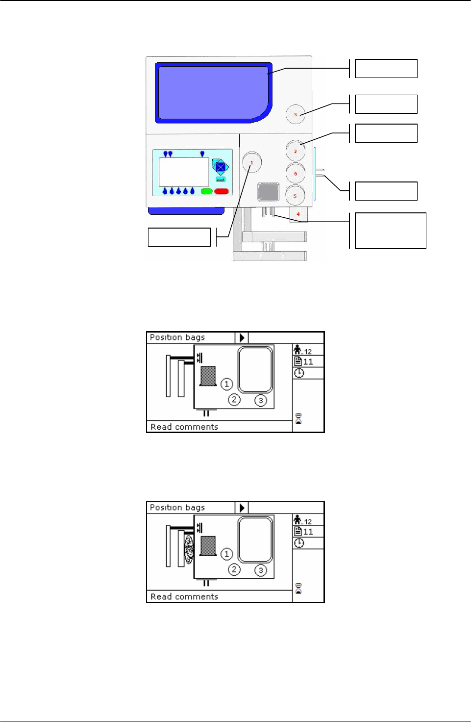
USING ARCHIMEDE
User Manual Revision 1.05 Page 75 of 105
Position bags and tubes according to the below sequence. Be sure to avoid tensions and folds
that might cause flow obstruction or weighing errors.
Picture 102: Kit installation aliquot separation procedure.
NOTE: Tubes in the various kits have different lengths. To simplify kits management, the
firmware allows to configure which valves you wish to enable.
Picture 103: Position primary bag aliquot separation procedure.
Hang the primary bag to the bag holders on the front panel. The label containing bag data
should always be turned outside.
Picture 104: Position aliquot separation procedure. bag.
Insert tubes from the bags on upper scale firmly into clamps 1 and 3.
Insert tubes from the bags on lateral scale firmly into clamp 2.
Primary bag
Scale 1
Clam
p
2
Scale 2
Clam
p
1
Clam
p
3
Scale 3
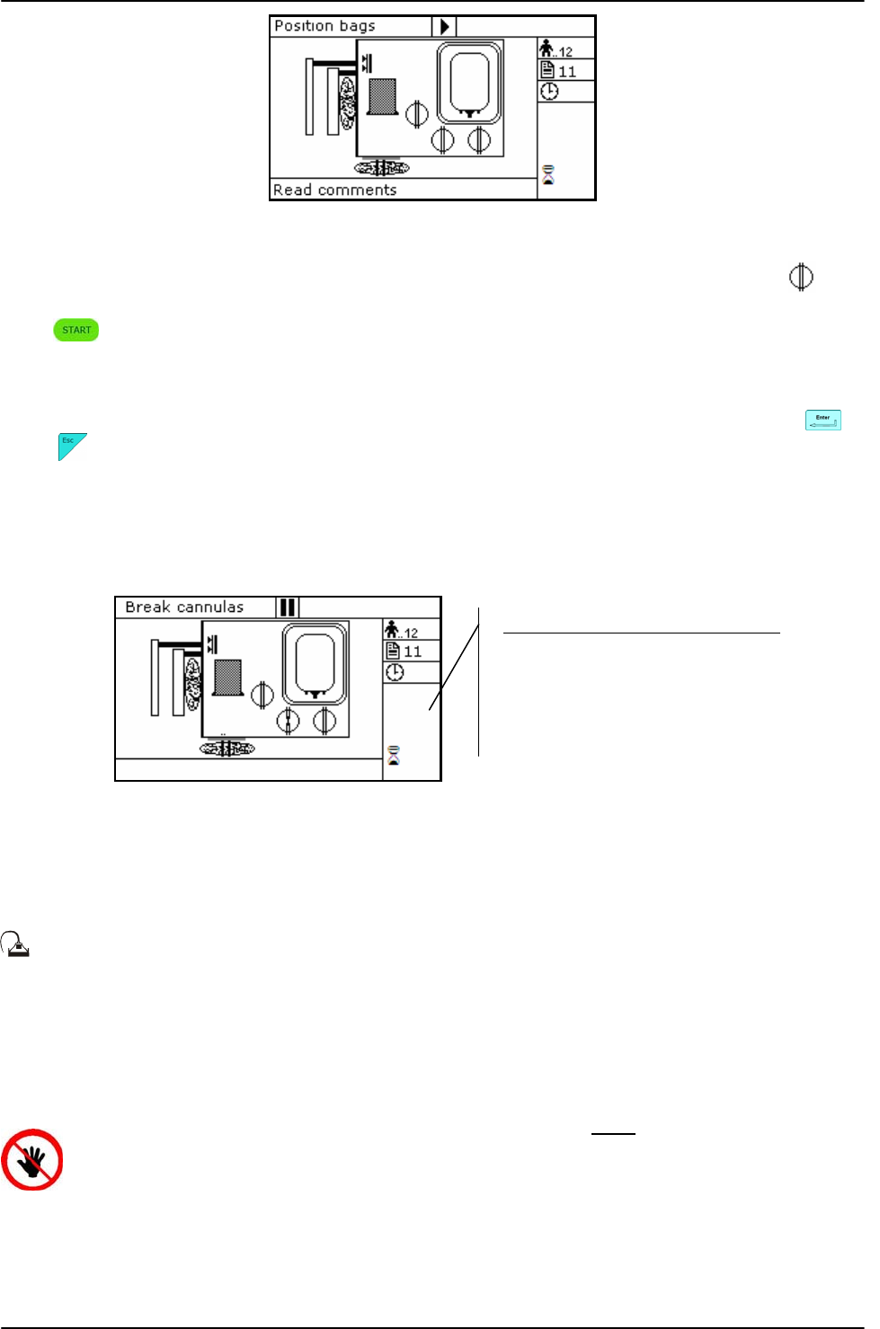
USING ARCHIMEDE
Page 76 of 105 User Manual Revision 1.05
Picture 105: Aliquot separation procedure bag in position.
Archimede checks correct tubes positioning inside proper clamps by mens of its optical
sensors. The tube is correctly inserted when the clamp number is replaced by the icon .
Press key-button to start the procedure.
If the primary bag expected weight check has been enabled through ArchimedeLINK and the
detected weight does not fall within the set limits, a warning will be displayed showing both
limits and current weight. After verifying the cause of the problem, confirm weight with or
press to leave the procedure. Furthermore, if the tube presence check is enabled the
display will show the clamp numbers where tubes are not correctly inserted and the procedure
will not start until all tubes are correctly inserted into the enabled clapms
Now wait for the plate to get close to the bag. The plate will exert a force corresponding to the
value set in the procedure parameters.
Picture 106: Break cannulas view aliquot separation procedure.
Break the cannulas by forcing on the side upper part of the cannula. Wait for a few seconds
that positive pressure is released.
During the procedure, possible comments can be read on the external part of the fix
front plate.
The graphic interface will now show the current operating phase number, and the weight value
of plasma collected. Archimede will check the bags weights. When the desired volume is
reached, the relevant clamp will be close. After the last aliquot the plate will move backwards
to standby position.
ATTENTION: THE FORCE SENSOR IS ENABLED ONLY WHEN THE PLATE MOVES
TOWARDS THE INSTRUMENT BODY.
CAUTION: DO NOT PUT YOUR HANDS IN THE PLATE WORKING AREA WHEN THE
PLATE IS MOVING.
At the end of the procedure the display will show the detected weights. If they are not the
expected ones, because tubes are not correctly placed and distort scales’ readings, the
Parameters of the ongoing phase:
#13: Plate forward moving speed.
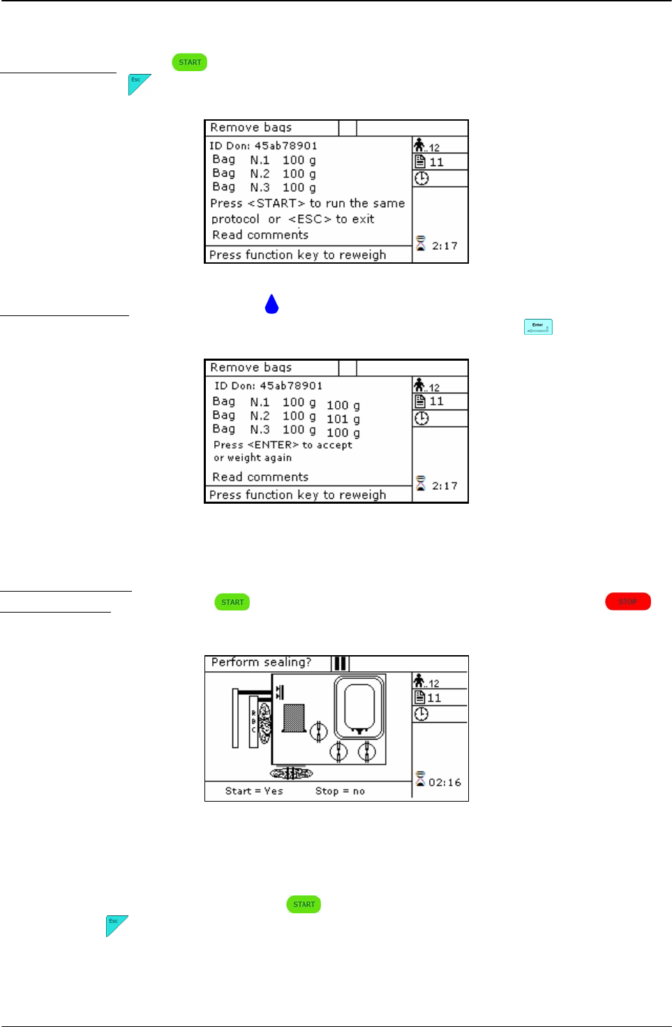
USING ARCHIMEDE
User Manual Revision 1.05 Page 77 of 105
emocomponents can be weighed again after correcting tubes’ position and the new weights
can be sent to ArchimedeLINK.
Correct weights: press keybutton to continue with the same type of separation or press
to go back to the page listing the procedures.
Picture 107: Viewing weight aliquot separation procedure.
Incorrect weights: prss one of the keybuttons to weigh emocomponents again. To accept
the new values and send them to ArchimedeLINK press
Picture 108: Reweight aliquot separation procedure.
The sealing cycle depends on the value set in the procedure parameters:
Automatic sealing: sealing cycle of the selected clamps is performed automatically.
Manual sealing: press keybutton to seal the enabled lines, or press to
continue, after confirming, without sealing.
Picture 109: Sealing in aliquot separation procedure
Archimede will automatically send to ArchimedeLINK all events and data of the procedure
performed.
Now remove tubes and bags and press to continue with another separation of the same
type ore press to exit.
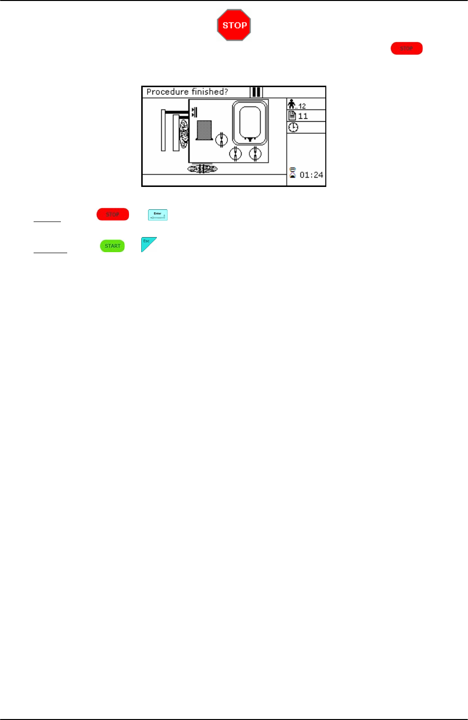
USING ARCHIMEDE
Page 78 of 105 User Manual Revision 1.05
If you need to interrupt the procedure either momentarily or definitively, press
keybutton.
Picture 110: Pause or Stop aliquot separation.
Stop: press or . Archimede will display the sealing page and send data to
ArchimedeLINK.
Pause: press or to continue the procedure.

USING ARCHIMEDE
User Manual Revision 1.05 Page 79 of 105
4.6.11 PROCEDURE 13 [d] T & T for RCC diluted in Plasma + Predefined HCT.
This procedure is suitable for triple bags to obtain diluted RCC in plasma with predefined
haematocrit (no additive solution) and PPP.
Parameters used:
1 During the procedure, checks that tubes are properly inserted into the clamps enabled for
the ongoing procedure.
2 Enables the routine controlling breaking of the primary bag cannulas.
3 Force in xx.x Kg beyond which the plate stops and waits for cannulas breaking.
4 Plate forward moving speed during cannulas breaking step.
5 Value used to calculate the force value below which the systems exits the cannulas
breaking routine. V =(force measured at breaking position) – (current force).
7 Value minimal of difference of reading between RBC and plasma with which it comes
controlled the bag before and during the procedure
9 Value of the maximum force applied during the procedure; the plate stops if the force
exceeds this limit.
11 Selection of the sealing mode. In automatic mode, the system automatically seals the
bags when the procedure is over. In manual mode, bags sealing must be confirmed.
12 Selection of clamps to be used for sealing when the procedure is over. Clamps are
numbered as follows: 1 Top, 2 Plasma, 4 Buffy, 8 Bottom. The value to be set in this
position is the value corresponding to the sum of the clamps used: for example, if bottom
and top are to be used, the value to be set is 9.
13 Plate moving speed used in the first phase for the management of force
15 Haematocrit target.
18 Value of the distance beyond which the system, after confirmation, stops the procedure if
no RBCs have been detected.
25 Tare of the primary bag. This value is used to calculate the product amount left in the
primary bag [current weight - tare]
40 Value allowing to select the clamps to be used in the procedure.
41 Number of the profile plate to be used with the ongoing procedure.
42 Enables the air elimination routine.
43 Primary bag positioning with blade ready for weighing.
44 Scale stability check.
45 Check Correlation Distance Weight.
46 Enable scale reading.
47 IR corresponding to upper and lower bag edges.
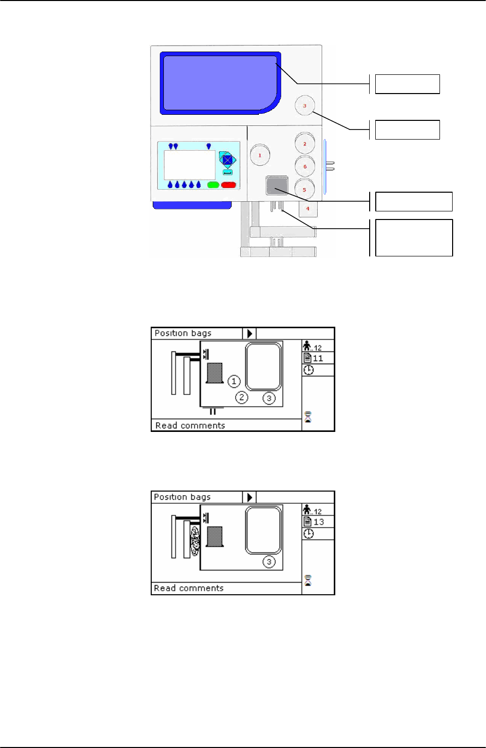
USING ARCHIMEDE
Page 80 of 105 User Manual Revision 1.05
Position bags and tubes according to the below sequence. Be sure to avoid tensions and folds
that might cause flow obstruction or weighing errors.
Picture 111: Kit installation procedure T & T with predefined HCT.
NOTE: .Tubes in the various kits have different lengths. To simplify kits management, the
firmware allows to configure which valves you wish to enable.
Picture 112: Position primary bag T & T with predefined HCT procedure.
Hang the primary bag to the bag holders on the front panel. The label containing bag data
should always be turned outside.
Picture 113: Position plasma bag T & T with predefined HCT procedure.
Open the cover of HB sensor and insert the tube coming from the primary bag into the
reading area. Close the cover.
Insert the tube coming from the HB sensor firmly into clamp 3.
Position the plasma bag on upper scale.
Primary bag
Scale 1
RBC Sensor
Clam
p
3
Scale 2
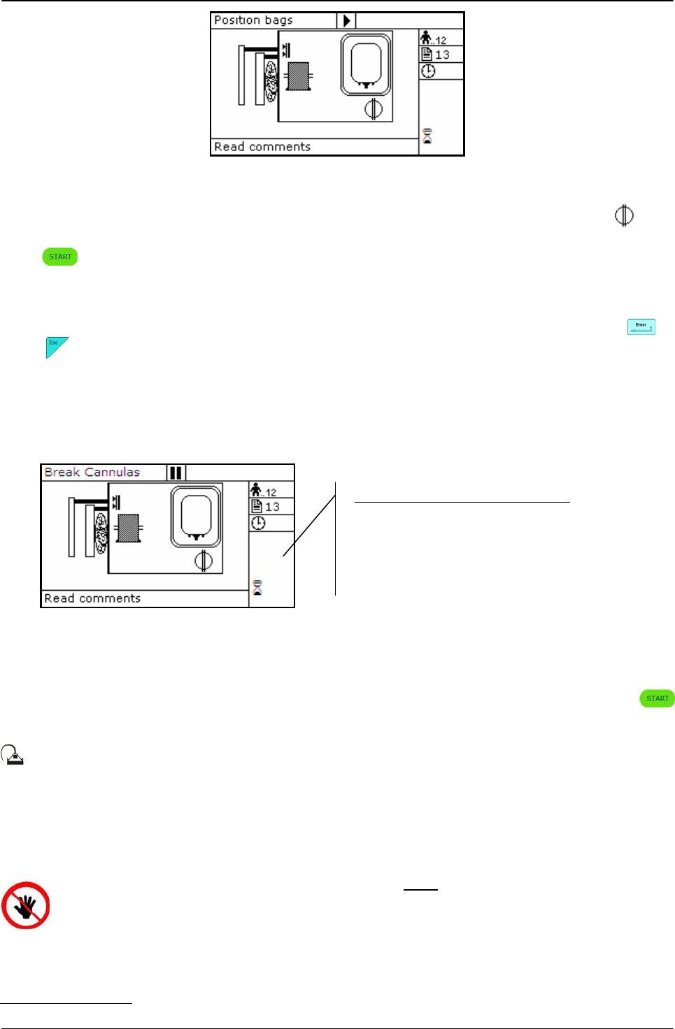
USING ARCHIMEDE
User Manual Revision 1.05 Page 81 of 105
Picture 114: T & T with predefined HCT procedure bag in position.
Archimede checks correct tubes positioning inside proper clamps by mens of its optical
sensors. The tube is correctly inserted when the clamp number is replaced by the icon .
Press key-button to start the procedure.
If the primary bag expected weight check has been enabled through ArchimedeLINK and the
detected weight does not fall within the set limits, a warning will be displayed showing both
limits and current weight. After verifying the cause of the problem, confirm weight with or
press to leave the procedure. Furthermore, if the tube presence check is enabled the
display will show the clamp numbers where tubes are not correctly inserted and the procedure
will not start until all tubes are correctly inserted into the enabled clapms
Now wait for the plate to get close to the bag. The plate will exert a force corresponding to the
value set in the procedure parameters.
Picture 115: Break cannulas view procedure T & T with predefined HCT.
Brake the cannulas by forcing on the side upper part of the cannula. Wait for a few seconds
that positive pressure is released. After detecting pressure decrease, Archimede automatically
starts the separation cycle. If pressure does not decrease below the set value, due to tube
obstruction or fluid clogging, it is anyway possible to force the cycle start by pressing
keybutton.
During the procedure, possible comments can be read on the external part of the fix
front plate.
The graphic interface will now show the current operating phase number, and the weight value
of plasma collected. Archimede will check the erythrocytes level and distance in primary bag.
When this level reaches the HCT target will stop and the plate will move backwards.
ATTENTION: THE FORCE SENSOR IS ENABLED ONLY WHEN THE PLATE MOVES TOWARDS
THE INSTRUMENT BODY.
CAUTION: DO NOT PUT YOUR HANDS IN THE PLATE WORKING AREA WHEN THE PLATE IS
MOVING.
The sealing cycle depends on the value set in the procedure parameters:
Automatic sealing: sealing cycle of the selected clamps is performed automatically.
Parameters of the ongoing phase:
#13: Plate forward moving speed
#18: Action distance
#15: Haematocrit target
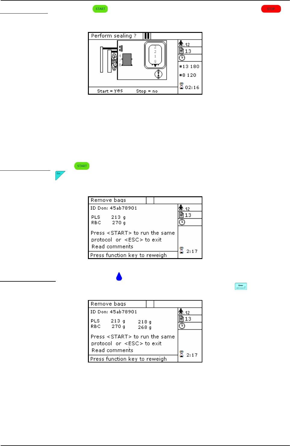
USING ARCHIMEDE
Page 82 of 105 User Manual Revision 1.05
Manual sealing: press keybutton to seal the enabled lines, or press to
continue, after confirming, without sealing.
Picture 116: Sealing procedure RCC T & T with predefined HCT.
Archimede will automatically send to ArchimedeLINK all events and data of the procedure
performed.
At the end of the procedure the display will show the detected weights. If they are not the
expected ones, because tubes are not correctly placed and distort scales’ readings, the
emocomponents can be weighed again after correcting tubes’ position and the new weights
can be sent to ArchimedeLINK again.
Correct weights: press keybutton to continue with the same type of separation or press
to go back to the page listing the procedures.
Picture 117: Viewing RCC T & T with predefined HCT procedure.
Incorrect weights: press one of the keybuttons to weigh emocomponents again. To accept
the new values and send them to ArchimedeLINK press
Picture 118: Reweight T & T with predefined HCT procedure.
With ArchimedeLINK the normal limits check can be activated. If it is enabled and the detected
weights do not fall within the set limits, the display will show the emocomponents’ detected
weights and the allowed limits. Press any key to continue.
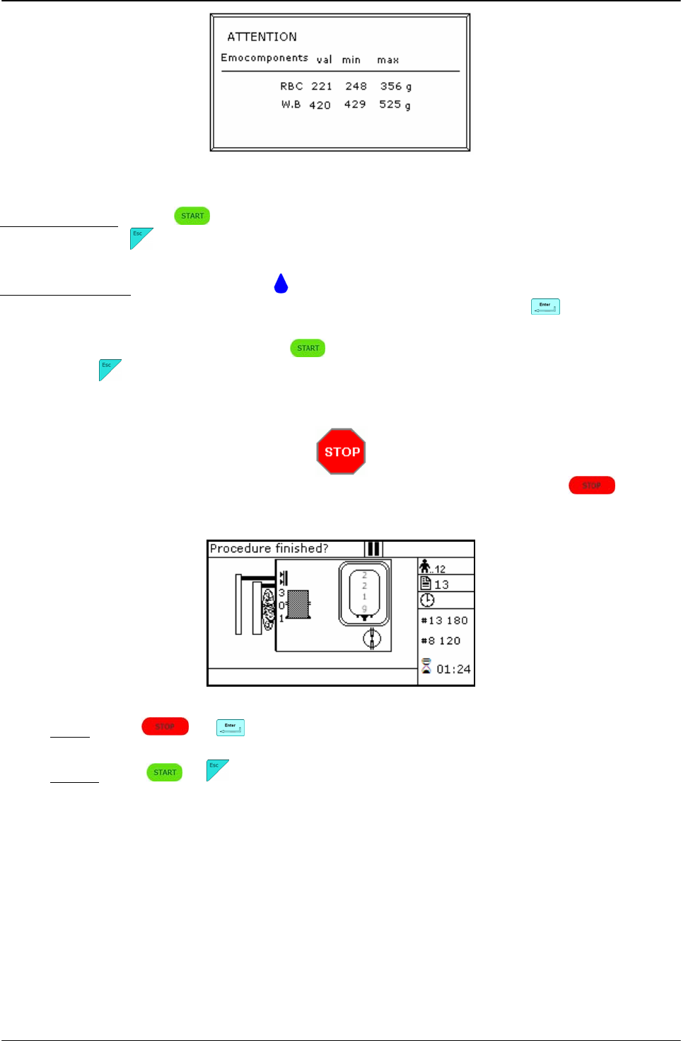
USING ARCHIMEDE
User Manual Revision 1.05 Page 83 of 105
Picture 119: RCC T & T with predefined HCT procedure with weight out of normal range.
Correct weights: press keybutton to continue with the same type of separation or press
to go back to the page listing the procedures.
Incorrect weights: press one of the keybuttons to weigh emocomponents again. To accept
the new values and send them to ArchimedeLINK press
Now remove tubes and bags and press to continue with another separation of the same
type or press to exit.
If you need to interrupt the procedure either momentarily or definitively, press
keybutton.
Picture 120: Pause or Stop procedure RCC T & T with predefined HCT.
Stop: press or . Archimede will display the sealing page and send data to
ArchimedeLINK.
Pause: press or to continue the procedure.

USING ARCHIMEDE
Page 84 of 105 User Manual Revision 1.05
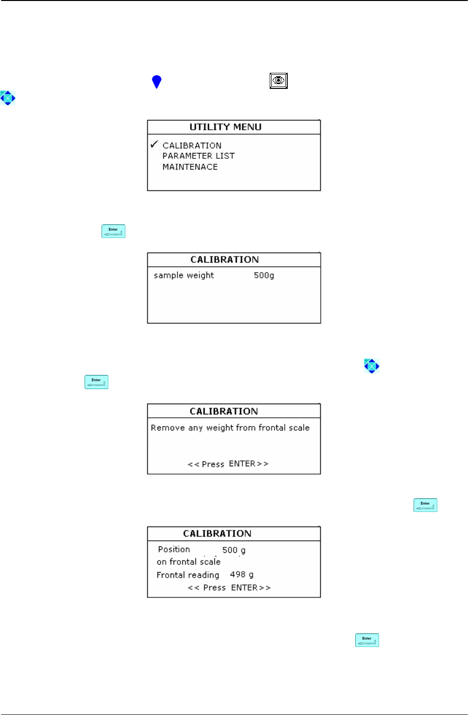
CALIBRATION
User Manual Revision 1.05 Page 85 of 105
5 SCALE CALIBRATION
Scale calibration can be performed only when Archimede has been switched on for a few
minutes. This is necessary for measuring sensors to reach thermal stabilization. A set of
certified sample weights is also necessary.
To enter calibration, press the keybutton above the icon, and select CALIBRATION using
direction keybuttons.
Picture 121: Calibration menu.
Confirm by pressing .
Picture 122: Calibration, sample weight setting.
Select the sample weight value you intend to use for calibration using keybuttons, then
confirm pressing .
Picture 123: First step calibration.
To perform tare, remove any weight from the front scale and then confirm pressing .
Picture 124: Second step calibration.
Position the selected sample weight. When the displayed value is stable to confirm.
Repeat the above steps with upper scale (2) and lateral scale (3).
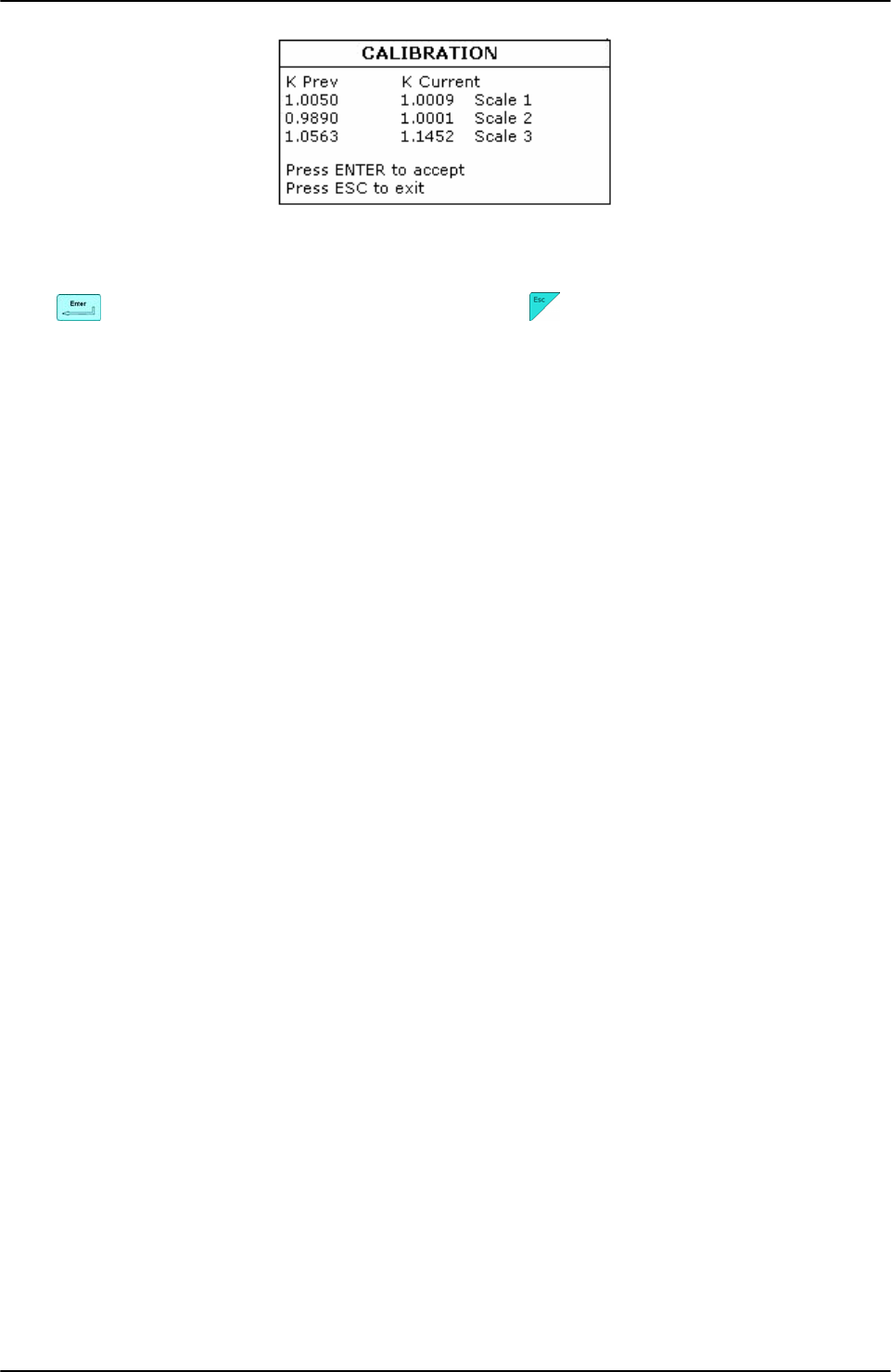
CALIBRATION
Page 86 of 105 User Manual Revision 1.05
Picture 125: Calibration, calibration factors display.
Verify calibration factors calculated for front scale (1), upper scale (2), and lateral scale (3).
Press to confirm factors and save them, or press to restore the previous calibration
factors.
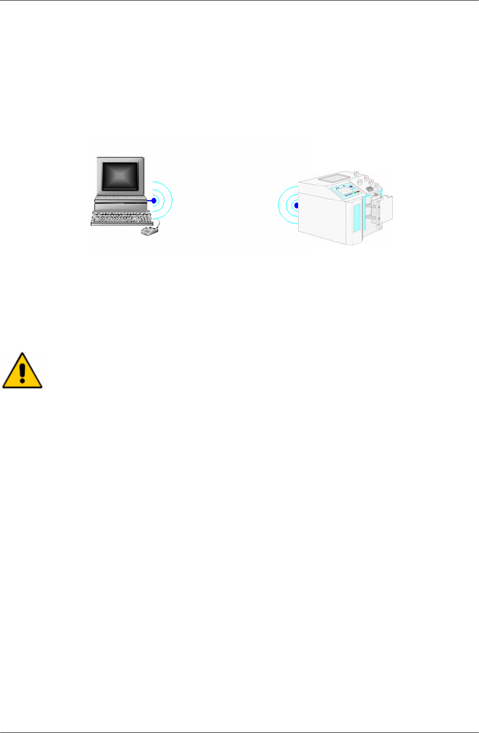
DATA TRANSFER
User Manual Revision 1.05 Page 87 of 105
6 DATA TRANSFER
When the WLAN option is installed, Archimede can dialogue in bidirectional mode with
ArchimedeLINK. This allows data transfer from more Archimede units, even if located several
meters distant from the PC where ArchimedeLINK server is installed. The maximum possible
distance is about 50 meters, depending on environment and disturbances that might be
present.
6.1 WLAN
Picture 126: WLAN connection
A 802.11 b/g wireless LAN should be installed on the PC to be used. Communication takes
place through the identification of Archimede’s univocal serial number. This allows
ArchimedeLINK to communicate with more units installed and switched on within a 50 meters
distance.
Designed by manufacturer for exclusive connection to the instrument according to
the prescriptions contained in the specific documentation of that instrument and to
EN60950 Regulation.
6.2 Firmware Update and Procedures Protocols
• The use of ArchimedeLINK allows to:
• Update Archimede’s internal firmware. Firmware updating should preferably be performed
by qualified engines authorized by manufacturer.
• Enter new procedures, up to a maximum of 18. New procedures creation should preferably
be performed by application engineers having detailed knowledge of the various procedure
parameters functions.
• Modify procedure parameters. This should be done by trained operators, or by application
engineers in order to avoid entering unsuitable values for the regular bag press operation.
• Verify correct operation of all peripheral units connected to Archimede. This operation
should be performed by qualified engineers authorized by manufacturer.
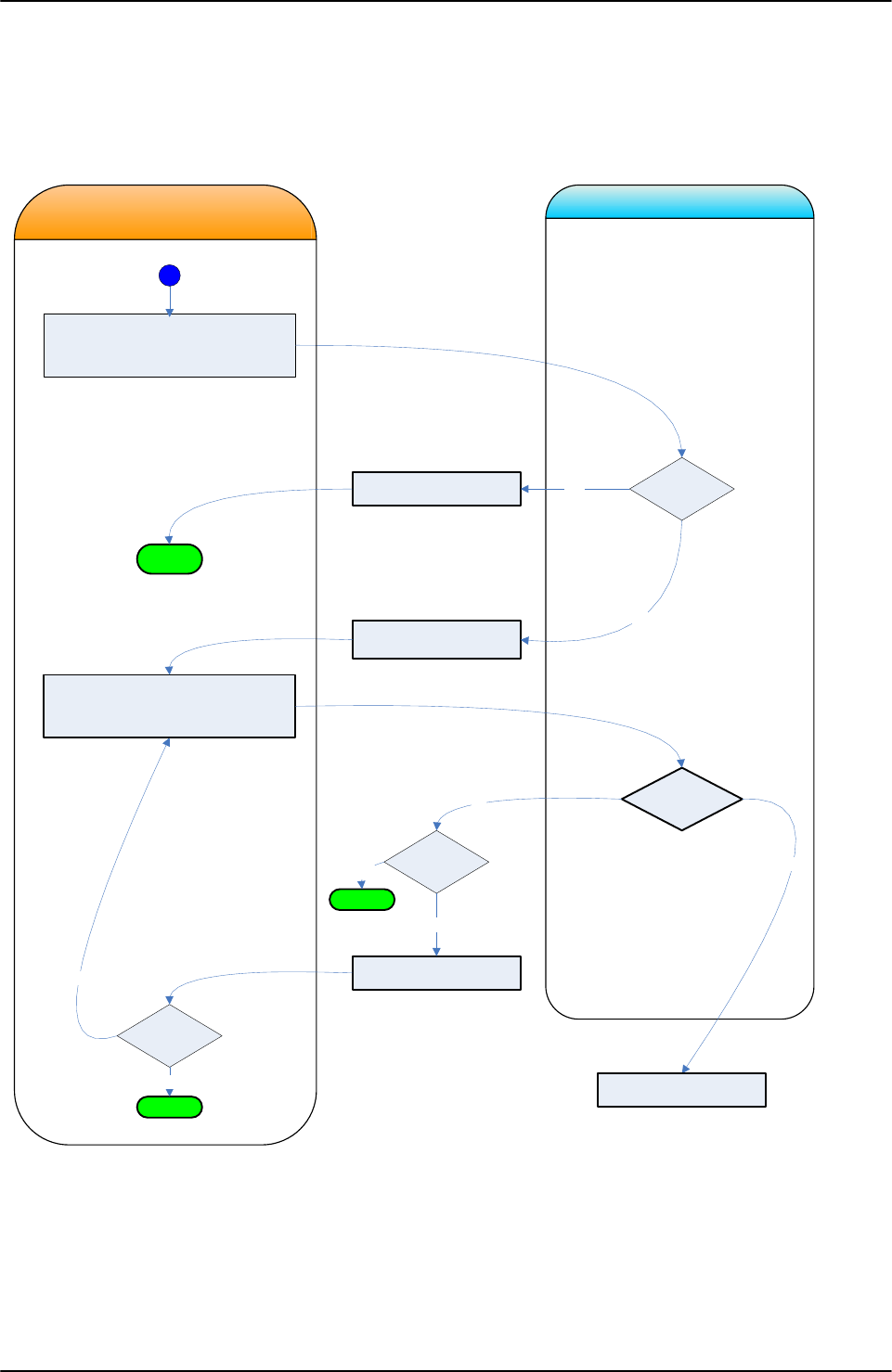
DATA TRANSFER
Page 88 of 105 User Manual Revision 1.05
6.3 Data transmission and reception
Data concerning the ongoing procedure are sent both during the procedure and at the end of
the procedure, with a round-up of all data acquired.
During the initial phase, Archimede sends Archimede‘s univocal serial number, the procedure
number and date and time of procedure beginning. In the final phase it sends all procedure
data and events or errors, if any.
STXID|……..|XOR|ETX
Send
Function Comand
STXID|ENQ|XOR|ETX
ID is serial number. Lenght max 4 digit zero
included.
SN NOK?
Busy?
STXID|NAK|XOR|ETX
STXID|ACK|XOR|ETX
OK for comunicazion
ArchimedeLINKComunication Request from
Archimede
Yes
Comand OK
No
Yes
Exit
STXID|NAK|XOR|ETX
Exit
No
3 NAK
Received ?
No
Yes
Exit
3 NAK
sent?
Yes
No
Manage request
Picture 127: Communication request from Archimede
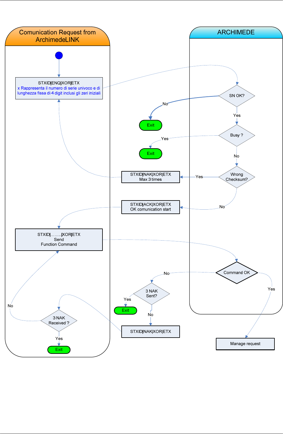
DATA TRANSFER
User Manual Revision 1.05 Page 89 of 105
Picture 128: Communication request from ArchimedeLINK

DATA TRANSFER
Page 90 of 105 User Manual Revision 1.05
6.3.1 Example of procedure data transmission:
Procedure preparation
# STXxxxx|0d|yy|XOR|ETX
STXxxxx|ACK|XOR|ETX
Procedure start
# STXxxxx|0e|yy|XOR|ETX
STXxxxx|ACK|XOR|ETX
Sealing in progress
# STXxxxx|0f|yy|XOR|ETX
STXxxxx|ACK|XOR|ETX
Procedure run and relevant data
# STXxxxx|0g|yy|OP|BC0|BC1|BC2|BC3|BC4|BC5|BC6|BC7|BC8|BC9|
hh:mm:ss|hh:mm:ss|hh:mm:ss|gg/mm/aa|
1111|2222|3333|cccc|ffff|ssss|hh:mm:ss|Events|Errors|XOR|ETX
STXxxxx|ACK|XOR|ETX
6.3.2 List of symbols used in the transmission protocol:
# Data transmission from Archimede to PC.
Data transmission from PC to Archimede.
STX Start of Text.
| Unit separator
ACK Acknowledge
XOR String control byte
ETX End of Text
xxxx Archimede‘s univocal serial number
0d Data string ID: procedure preparation
0e Data string ID: procedure start
0f Data string ID: sealing in progress
0g Data string ID: procedure run and relevant data
yy Procedure number
OP Operator code
BC 0,1,2,3,4,5,6,7,8,9 data read by barcode reader
hh:mm:ss 1st field procedure start time, 2nd field sealing start time, 3rd field time and
date procedure end
Weight of frontal scale
2222 Weight of upper scale
3333 Weight of lateral scale
cccc Amount of plasma used for cleaning
ffff Amount of plasma used for filter
ssss Amount of Sag.M.
Events Evens occurred during procedure
Errors Errors occurred during procedure

TROUBLESHOOTING
User Manual Revision 1.05 Page 91 of 105
7 TROUBLESHOOTING
Archimede checks continuously that the peripheral units connected work correctly. In case it
detects an error that cannot be eliminated through the dedicated algorithms, the instrument
displays the error.
7.1 Errors and Possible Solutions
Error 1A THE INSTRUMENT DOES NOT TURN ON.
Cause 1: Main power is lacking.
Remedy: Check that main voltage is present and that the power cord
is correctly plugged.
Cause 2: Fuse blown
Remedy: Replace burnt fuses with new ones of the type reported on
data plate.
Error 2A DATE AND TIME LOSS.
Cause 1: Reset of RTC circuit due to big conducted interferences.
Remedy: Re-set date and time.
Cause 2: RTC backup capacitor is exhausted.
Remedy: Call Authorized Service Center.
Error 3A THE DISPLAY SHOWS INCOMPREHENSIBLE CHARACTERS.
Cause 1: Electronics interferences.
Remedy: Turn Archimede OFF and ON.
Call Authorized Service Center.
Error 4A ARCHIMEDE DOES NOT CONNECT TO ARCHIMEDELINK.
Cause 1: ArchimedeLINK is not enabled or Archimede network is
disconnected.
Remedy: Enable ArchimedeLINK server.
Connect to Archimede WLAN network.
Check that Archimede and ArchimedeLINK server subnets
are correct.
Check firewall settings.
Cause 2: Noisy communication.
Remedy: Check signal strength and ensure that Archimede’s antenna
is correctly screwed on and is not near metal objects.
Bring access point or server nearer Archimede units.
Change the WLAN module transmission channel.
Call Authorized Service Center.
7.2 Errors with Archimede codes
Error 1 E2PROM BUSY.
Cause 1: E2prom memory stuck or defective.
Remedy: Turn Archimede OFF and ON.
Cause 2: Defective microcontroller E2prom memory.
Remedy: Call Authorized Service Center.
Error 2 E2PROM VERIFY.
Cause 1: E2PROM verify failed.
Remedy: Turn Archimede OFF and ON.
Cause 2: Defective microcontroller E2prom memory.
Remedy: Call Authorized Service Center.

TROUBLESHOOTING
Page 92 of 105 User Manual Revision 1.05
Error 3 SPI TIMEOUT
Cause 1: One peripheral unit has unexpectedly interrupted the
communication.
Remedy: Turn the instrument OFF and ON.
Cause 2: Defective CPU or SO board.
Remedy: Call Authorized Service Center.
Error 4 RFID TIMEOUT
Cause 1: Defective RFID label.
Remedy: Replace RFID label.
Cause 2: RFID module is not responding.
Remedy: Turn the instrument OFF and ON.
Error 5 RFID COMUNICATION ERROR
Cause 1: RFID data are corrupted.
Remedy: Turn the instrument OFF and ON.
Error 6 CORRUPTED BOOT LOADER
Cause 1: Checksum of boot loader routine is not correct.
Remedy: Call Authorized Service Center.
Error 7 CORRUPTED FIRMWARE
Cause 1: Checksum of firmware is not correct.
Remedy: Download firmware by ALNK.
Error 8 WRONG CALIBRATION DATE
Cause 1: Data loss or corrupted.
Remedy: Run scales calibration.
Error 9 PARAMETER OVER RANGE
Cause 1: During parameter check an error in parameter value has
been detected.
Remedy: Run procedure update.
Error 10 (1-4) AD CONVERTER IS IN OVERFLOW.
Cause 1: Incorrect analog power
Remedy: Check that scale holders are correctly mounted and free
from obstructions.
Turn Archimede OFF and ON.
Error 11 (1-4) AD CONVERTER TIMEOUT.
Cause 1: A/D converter stuck.
Remedy: Turn Archimede OFF and ON.
Error 12 (1-4) ADC UNDERFLOW DURING SCALE (X) TARE.
Cause 1: Scale holder is not in correct position.
Remedy: Check that scale holders are correctly mounted and free
from obstructions.
Turn Archimede OFF and ON.
Error 13 (1-4) SCALE (X) TARE IS OVER LIMITS.
Cause 1: Scale holder is not in correct position.
AD input circuit not compensated.

TROUBLESHOOTING
User Manual Revision 1.05 Page 93 of 105
Remedy: Check that scale holders are correctly mounted and free
from obstructions.
Turn Archimede OFF and ON.
Error 14 (1-4) IN SEPARATION MODE TARE (X) VALUE IS OVER RANGE.
Cause 1: Weight detection circuit output ≥ 1000 mV.
Remedy: Remove any extra weight from the cradle. Call Authorized
Service Center.
Error 15 (1-4) K SCALES (X) VALUE OVERRANGE.
Cause 1: During calibration, the system has checked that scales
calibration factor is over limit. The value of standard weight
in use does not correspond to the value set during
calibration..
Remedy: Repeat calibration.
Call Authorized Service Center.
Error 16 (1-10) LUMINOSITY.
Cause 1: There is too much light in the room. IR dark voltage > 500
mV.
Remedy: Reduce environment luminosity.
Cause 2: IR sensor is defective.
Remedy: Call Authorized Service Center.
Error 17 (1-10) IR SENSOR SENSITIVITY TOO LOW.
Cause 1: IR sensor does not detect sufficient difference between lit
and unlit led. Vtr < 4500mV with I led > 300 mA.
Remedy: Clean IR sensors and yellow strip.
Cause 2: IR sensors pair is defective.
Remedy: Call Authorized Service Center.
Error 18 (1-10) IR SENSOR SENSITIVITY TOO HIGH.
Cause 1: IR sensor detects too much difference between lit and unlit
led.
Remedy: Reduce environment luminosity.
Cause 2: IR sensors pair is defective.
Remedy: Call Authorized Service Center.
Error 19 HB SENSOR SENSITIVITY TOO LOW.
Cause 1: HB sensor does not detect sufficient variation between lit
and unlit led.
Remedy: Clean sensors.
Cause 2: Green sensors is defective.
Remedy: Call Authorized Service Center.
Error 20 HB SENSOR SENSITIVITY TOO HIGH.
Cause 1: HB sensor detects too high variation between lit and unlit
led.
Remedy: Call Authorized Service Center.

TROUBLESHOOTING
Page 94 of 105 User Manual Revision 1.05
Error 21 PLATE OPENING MOVING TIME TO LIMIT POSITION >30 SECONDS.
Cause 1: Mechanical obstructions prevent the pressing plate from
reaching open position. Time > 30 seconds.
Remedy: Remove any obstruction. Clean support bars.
Cause 2: Open position sensor defective.
Remedy: Call Authorized Service Center.
Error 22 PLATE CLOSING MOVING TIME TO LIMIT POSITION >30 SECONDS.
Cause 1: Mechanical obstructions prevent the pressing plate from
reaching close position. Time > 30 seconds.
Remedy: Remove any obstruction. Clean support bars.
Cause 2: Force sensor defective.
Remedy: Call Authorized Service Center.
Error 23 BLADE MOVING TIME TO LIMIT POSITION >10 SECONDS.
Cause 1: Mechanical obstructions prevent the buffy coat separator
from reaching open or close position within 10 seconds.
Remedy: Remove any obstruction, Clean blade assy.
Cause 2: BC position sensor defective.
Remedy: Call Authorized Service Center.
Error 24 PLATE POSITIONING TIME TO HOME POSITION >30 SECONDS.
Cause 1: Mechanical obstructions prevent plate movement from
reaching home position within 30 seconds..
Remedy: Remove any obstruction.
Cause 2: Home position sensor defective.
Remedy: Call Authorized Service Center.
Error 25 POSITIONING TIME OF IR CALIBRATION POSITION SENSOR > 10
SECONDS.
Cause 1: Mechanical obstructions prevent plate movement from
reaching IR calibration position within 10 seconds..
Remedy: Remove any obstruction.
Cause 2: IR cal position sensor defective.
Remedy: Call Authorized Service Center.
Error 26 PLATE ZERO-POSITION SENSOR OVER RANGE.
Cause 1: Mechanical obstructions prevent plate movement from
reaching zero position.
Remedy: Remove any obstruction.
Cause 2: Distance sensor defective.
Remedy: Call Authorized Service Center.
Error 27 FORCE SENSOR HAS DETECTED STRESS >1 WITH PLATE FREE.
Cause 1: Mechanical obstructions prevent to correlate values
between distance and force during self-check.
Remedy: Remove any obstruction.
Cause 2: Force sensor is defective.
Remedy: Call Authorized Service Center.
Error 28 CALIBRATION POSITION DISTANCE SENSOR VOLTAGE > 4600 mV.
Cause 1: Mechanical obstructions prevent plate movement.

TROUBLESHOOTING
User Manual Revision 1.05 Page 95 of 105
Remedy: Remove any obstruction.
Cause 2: Defective linear sensor.
Remedy: Call Authorized Service Center.
Error 29 (1-4) WET OR DIRTY ELECTRODES IN SEALING HEAD.
Cause 1: Sealing heads wet or dirty.
Remedy: Clean and dry sealing heads’ electrodes. Press keybutton
to open the clamp in error; insert tube again and press
to perform sealing again. If a procedure is ongoing, press
to continue.
Cause 2: Defective sealing head or CSU.
Remedy: Call Authorized Service Center.
Error 30 SEALING UNIT BUSY.
Cause 1: CSU cable disconnected.
Remedy: Check and connect cable.
Cause 2: Defective CSU.
Remedy: Call Authorized Service Center.
Error 31 TUBE IN THE CLAMP.
Cause 1: Tubes are inserted to clamps during self-diagnosis.
Remedy: Remove tubes from clamps and repeat self-diagnosis cycle.
Cause 2: Defective tube sensor.
Remedy: Call Authorized Service Center.
Error 32 (1-4) ELEVATED LOAD CELLS OFFSET.
Cause 1: Bags or weights positioned on the scales during self-
diagnosis.
Remedy: Remove any bags or weights from the scales during self-
diagnosis cycle.
Cause 2: Defective offset digital system.
Remedy: Call Authorized Service Center
Error 33 ELEVATED FLOW-VALVE CHECK CYCLE.
Cause 1: Valve-actuator movement is locked.
Remedy: Remove tubes or any obstruction from the actuator and
retry. Check if cable is inserted correctly. Replace flow valve
assy.
Cause 2: Defective position sensor.
Remedy: Call Authorized Service Center.
Error 34 STEP NUMBER UNSUITABLE FOR COMPLETING ONE FLOW-VALVE
CYCLE.
Cause 1: Valve-actuator movement is locked.
Remedy: Remove tubes or any obstruction from the actuator and
retry. Check if cable is inserted correctly. Replace flow valve
assy.
Cause 2: Defective motor.
Remedy: Call Authorized Service Center.

TROUBLESHOOTING
Page 96 of 105 User Manual Revision 1.05
Error 35 (1-3) CELL K OVER RANGE.
Cause 1: In self test phase, during calibration factors check an error
has been detected.
Remedy: Ricalibrate all scales.
Error 36 FORCE SENSOR K OVER RANGE.
Cause 1: In self test phase, during calibration factor check an error
has been detected.
Remedy: Ricalibrate force sensor.
Error 37 INSUFFICIENT PLASMA-PLT.
Cause 1: The plasma amount set in the procedure is higher than the
amount collected.
Remedy: Verify actual value.
Cause 2: Scale not calibrated.
Remedy: Calibrate scale.
Error 38 INSUFFICIENT PLASMA WEIGHT.
Cause 1: During separation plasma weight is not adequate.
Remedy: Check that the cannula has broken and that there are no
obstructions; then go on.
Error 39 INSUFFICIENT BUFFY-COAT.
Cause 1: The buffy-coat amount set in the procedure is higher than
the amount collected.
Remedy: Verify actual value.
Cause 2: Scale not calibrated.
Remedy: Calibrate scale. (see scale calibration)
Error 40 INSUFFICIENT SAG-M WEIGHT.
Cause 1: Sag-M amount is insufficient to complete the procedure.
Remedy: Check actual amount and confirm.
Cause 2: Scale not calibrated.
Remedy: Calibrate scale (see scale calibration).
Error 41 CHECK SAG-M FLOW.
Cause 1: Sag-M tube folded or collapsed.
Remedy: Adjust bag tube and remove obstructions.
Cause 2: Clamp 5 closed.
Remedy: Unlock clamp 5.
Call Authorized Service Center.
Cause 3: Scale not calibrated.
Remedy: Calibrate scale (see scale calibration).
Error 42 LIMIT SWITCH REACHED WITH INSUFFICIENT SAG-M.
Cause 1: Sag-M bag lacking. The system has detected the all-
opened-plate sensor without dispensing Sag-M.
Remedy: Position Sag-M bag.
Cause 2: Defective open-plate sensor.
Remedy: Call Authorized Service Center.
Error 43 RBCS NOT DETECTED.

TROUBLESHOOTING
User Manual Revision 1.05 Page 97 of 105
Cause 1: Wrong action threshold.
Remedy: Check value of parameters 8.
Cause 2: Wrong distance threshold.
Remedy: Check value of parameters 18.
Cause 3: Insufficient erythrocytes amount.
Remedy: Repeat procedure.
Cause 4: Defective HB sensor.
Remedy: Call Authorized Service Center.
Error 44 CHECK FLOW.
Cause 1: Obstructed filter.
Remedy: Retry with a new bags set.
Cause 2: Tubes poorly positioned.
Remedy: Relocate tubes.
Cause 3: Scale not calibrated.
Remedy: Calibrate scale (see scale calibration).
Error 45 NOT IN USE.
Error 46 UNEXPECTED WEIGHT.
Cause 1: Scale weight has had a sudden variation due to an external
agent.
Remedy: Check that foreign objects are not on the scales and
remove it.
Cause 2: Scale unstable.
Remedy: Check if scale holder don’t touch against metal plate.
Call Authorized Service Center.
Error 47 BARCODE TOO LONG.
Cause 1: Barcode not compatible with the system. The maximum
possible length is 20 characters including the control
character.
Remedy: Read a compatible code.
Cause 2: Barcode reader set improperly.
Remedy: Reconfiguration of barcode (see Datalogic barcode
configuration).
Error 48 PROCEDURE HAS BEEN INTERRUPTED BY THE OPERATOR.
Cause 1: The operator has pressed key-button and confirmed
interruption with key-button.
Remedy: Repeat procedure.
Error 50 ERROR DISTANCE-WEIGHT.
Cause 1: The plate is in position where weight measured must be
more.
Remedy: Verify any obstructions that may create false weight
readings. Check bag setting parameters.
Error 51 ERRORE PESATA-DISTANZA.
Cause 1: The plate is in position where weight measured must be
less.

TROUBLESHOOTING
Page 98 of 105 User Manual Revision 1.05
Remedy: Verify any obstructions that may create false weight
readings. Check bag setting parameters.
Error 52 TIMEOUT PLATE.
Cause 1: The distance detected did not change over the last 18
seconds.
Remedy: Verify any obstructions of the tubes and proper breaking of
cannula.
Error 53 (1-6) HIGH SENSOR TUBE LIGHT.
Cause 1: Ambient light detected by the sensor tube x is too high.
Remedy: Reduce ambient light. Change tube sensor (x).
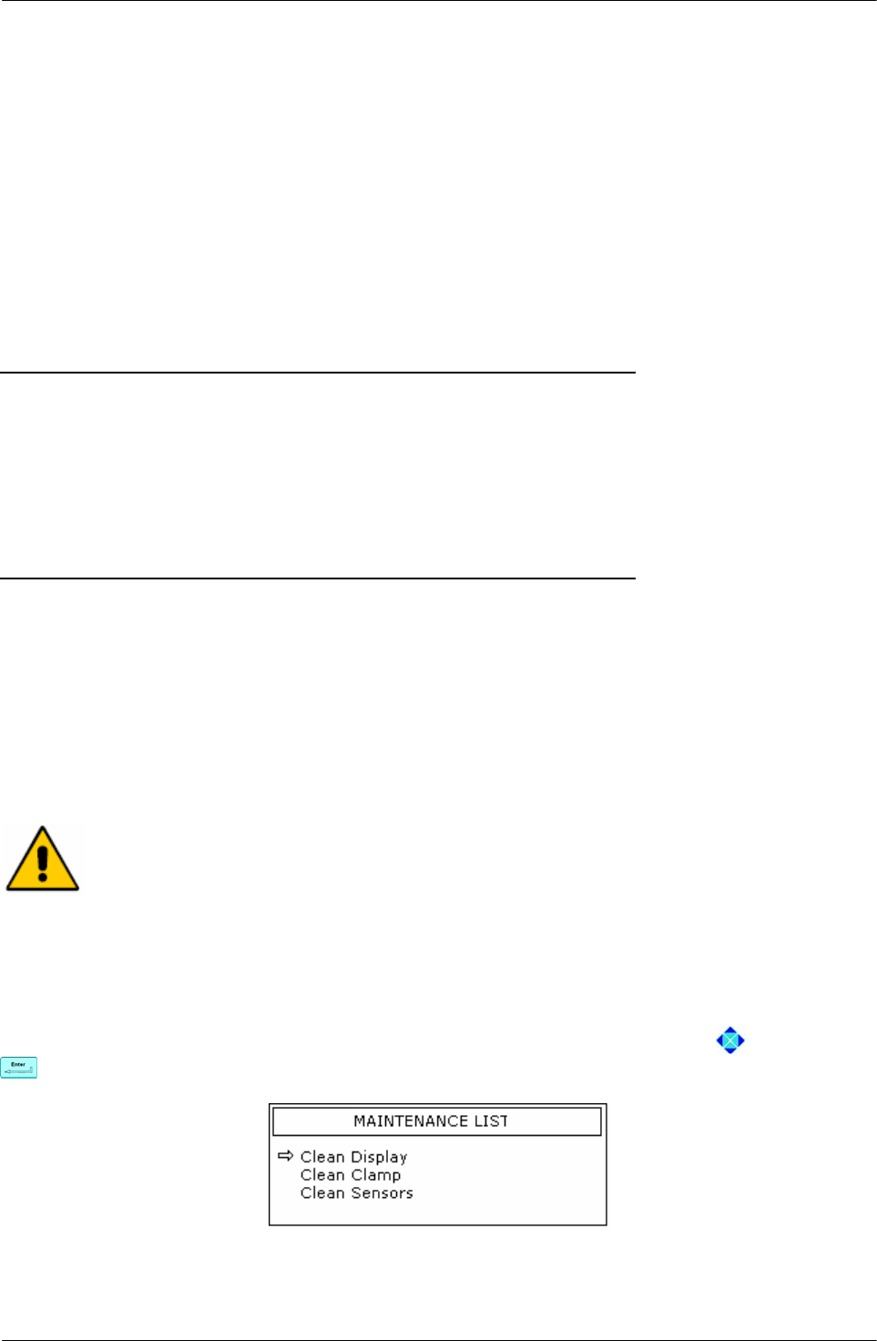
MAINTENANCE
User Manual Revision 1.05 Page 99 of 105
8 Maintenance
Archimede requires very little maintenance. It simply consists in keeping clean case, clamps,
flow valve, optical sensors and the weighing system calibration control.
8.1 Daily Maintenance
8.1.1 Cleaning
Clean upper scale tray and holder with detergent or disinfectant; avoid hitting the mechanical
device supporting the tray and do not pour liquids inside the central gap.
Clean clamps hollow and its actuator with a wet cotton wad.
Clean Archimede case with disinfectant. Keyboard and optical sensors should be cleaned only
with a cloth dampened with water.
Never use alcohol, acetone, trichloroethylene or any solvents.
8.1.2 Decontamination
Remove the upper scale tray and decontaminate both tray and holder with bleach or
disinfectant. Do not hit the mechanical device supporting the tray and do not pour liquids
inside the central gap. Decontaminate also flow-valve actuator, clamps actuators and optical
sensors with a cotton fioc dampened with bleach or disinfectant. Rinse with water all parts
treated with bleach or disinfectant.
Never use alcohol, acetone, trichloroethylene or any solvents.
8.1.3 Monthly Maintenance
Monthly maintenance simply consists of checking scales calibration. The check should be
performed by a certificate centre with certified weights. If the reading does not fall within the
allowed range, please contact the authorized technical service centre.
8.2 Yearly Maintenance
Yearly maintenance is performed by qualified engineers authorized by manufacturer.
Before cleaning with any liquid, turn Archimede off and disconnect the
power cable.
8.3 Maintenance Recording
This function is enabled only when Archimede is connected to ArchimedeLINK. In this case, all
maintenance operations can be stored sending to ArchimedeLINK data relevant to
maintenance, operator, and date of performance.
To confirm the action done, select the desired maintenance using the arrows , confirm with
and read the operator code.
Picture 129: Maintenance view

MAINTENANCE
Page 100 of 105 User Manual Revision 1.05

OPTIONAL ACCESSORIES
User Manual Revision 1.05 Page 101 of 105
9 ACCESSORIES
Archimede can be supplied with:
RFID reader for labels or cards type RFID ISO15693. Supported tags are I.CODE SLI
and Tag_it.
Omnidirectional bar code reader.

OPTIONAL ACCESSORIES
Page 102 of 105 User Manual Revision 1.05
DISPOSAL
User Manual Revision 1.05 Page 103 of 105
10 DISPOSAL
When disposing materials, please observe the following recommendations:
10.1 Packing Material Disposal
• Throw packing materials in the proper separate collection containers.
• In case of doubts, please ask the blood centre chief for information about proper separate
collection.
10.2 Archimede Disposal
• If Archimede is no longer usable, please bring it to the area separate collection centre
or
• Ask the nearest Technical Service authorized centre.
Separate waste collection.
Discard separately.

DISPOSAL
Page 104 of 105 User Manual Revision 1.05

TECHNICAL FEATURES
User Manual Revision 1.05 Page 105 of 105
11 TECHNICAL FEATURES
• Painted metal case.
• Graphic backlight display 240 x 128.
• N° 3 load cells for 2 kg: non linearity 0,02% F.S., repeatability 0,02% F.S., resolution ± 1 g.
• Detection system of force exerted by the plate.
• N° 4 sealing head clamps, 1 normal clamp, and one flow valve.
• N° 10 optical sensor to detect buffy coat level.
• Optical device to detect red blood cells presence.
• Many separation procedures stored, up to a maximum of 18.
• WLAN for bi-directional data transfer of procedure and configuration data.
• PS2 port for external barcode-reader connection.
• Adjustable sealing time from 0.5 to 4 seconds, frequency 40.68 MHz.
• Environmental requirements: Temperature between 5°C and 45°C Humidity lower
than 80% without condensation.
• Power supply: 90 VAC 84 W 1A, 230 VAC 81 W 0.4A, fuses 2.0 AT.
• Dimensions Width 435, depth 500, height 425 [mm].
• Weight: 40Kg
• Transport and storage From –20°C to +70°C. Relative humidity from
temperature 20% to 90% without condensation.
• In accordance with: EN60601-1-2 (2001-11)
IEC60601-1-2 (2001-09)
EN60601-1:1990-08+ EN60601-1/Ec :1994-07 +
EN60601-1/A1:1993+EN60601-1/A1/Ec:1994-07 +
EN60601-1/A2:1995-06 + EN60601-1/A13:1996-01.
EN60950-1(2001) + A1
EN301 489-17 V1.2.1 (2002-08).
EN301 489-1 V1.6.1 (2005-09).
• Electrical safety: Class I – Instrument with applied part Type B.
Rule 12 MDD 93/42 – Device belonging to Class
I without measurement function.
Instrument not suitable for use in the presence of
flammable anaesthetic mixtures with air or oxygen
or nitrous oxide. Instrument for continuous working.
• Instrument in compliance with MDD 93/42 EEC requirements.
• International protection: IP41.
• FCC ID: V991504.
MOELCA s.r.l.
Sede Legale Via E.Toti,101 Uffici Via del Lavoro,19.
22070 Limido Comasco (CO)
031-3520153 3520279 3524739.
Fax 031-3524732 Email: info@moelca.it