Contents
- 1. User Manual - Part 1
- 2. User Manual - Part 2
User Manual - Part 2
51
CHAPTER II: BASICS STARex MANUAL
When a Basic program is running there will be a message on the top showing the Basic Program is running:
Note: The Basic program won’t be lost upon reboot.
See this section for more information about running the Basic Program
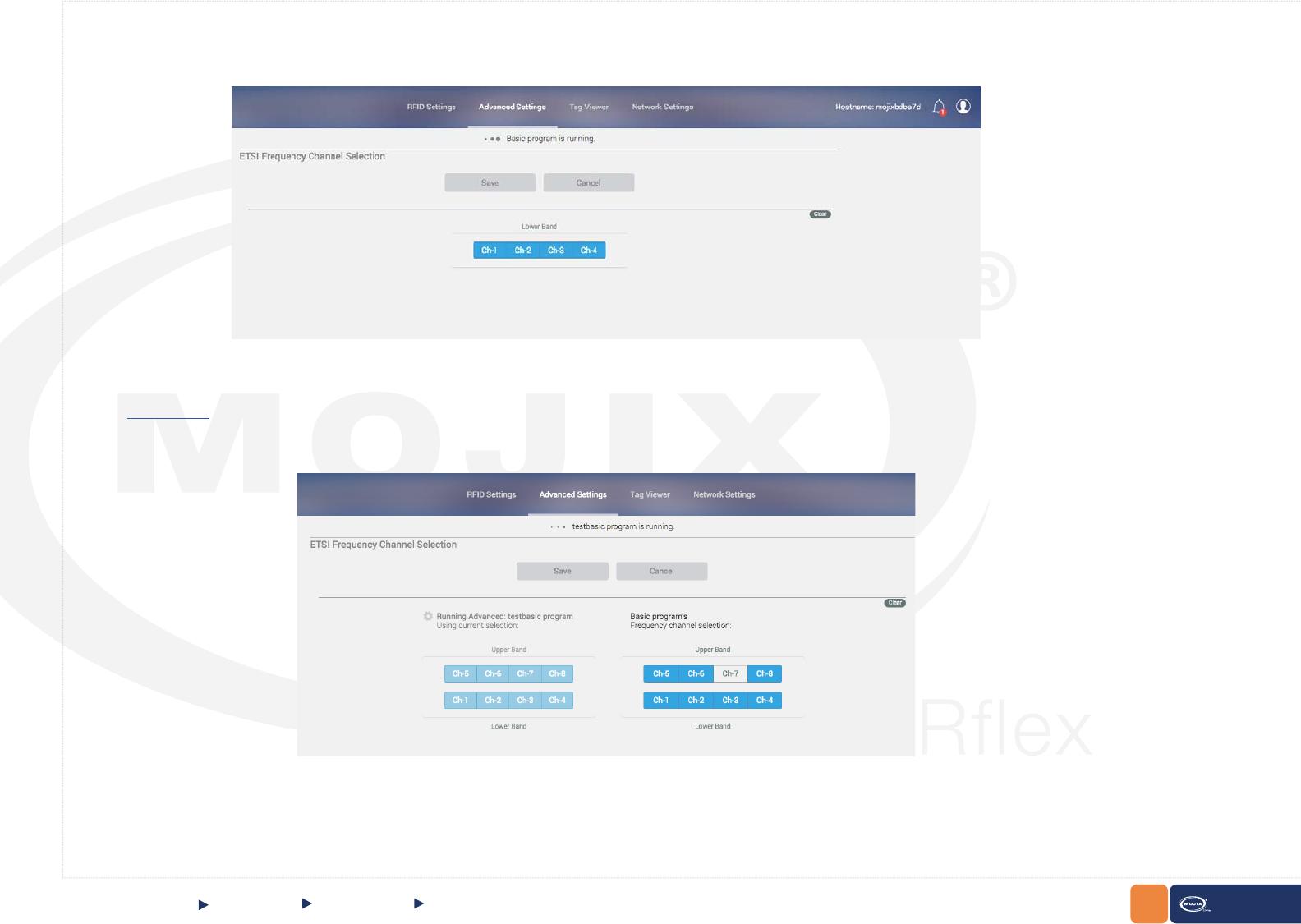
When an Advanced program is running the Frequency Channel displays information of the congured channels
Channel selection for a running advanced program is read only, while the Basic program’s buttons can be changed.
QUICK START Advanced Mode Frequency Channel
52
CHAPTER II: BASICS STARex MANUAL
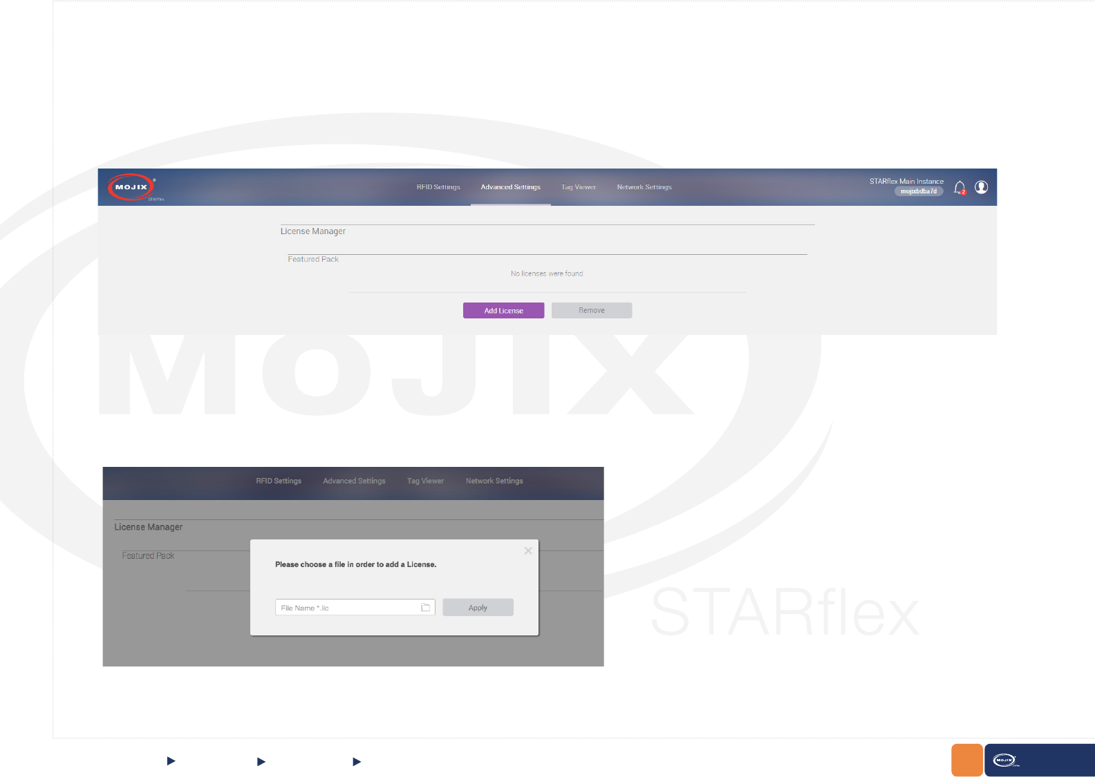
To upload a license, click on the Add License button:
To remove a license click on the Remove button. Note that the STARex must be rebooted.
QUICK START
License Manager
The “License Manager” page allows the users to upload and add or remove licenses to the STARex. For detailed information please refer to Chapter
VI - License Manager.
Advanced Mode License Manager
53
CHAPTER II: BASICS STARex MANUAL
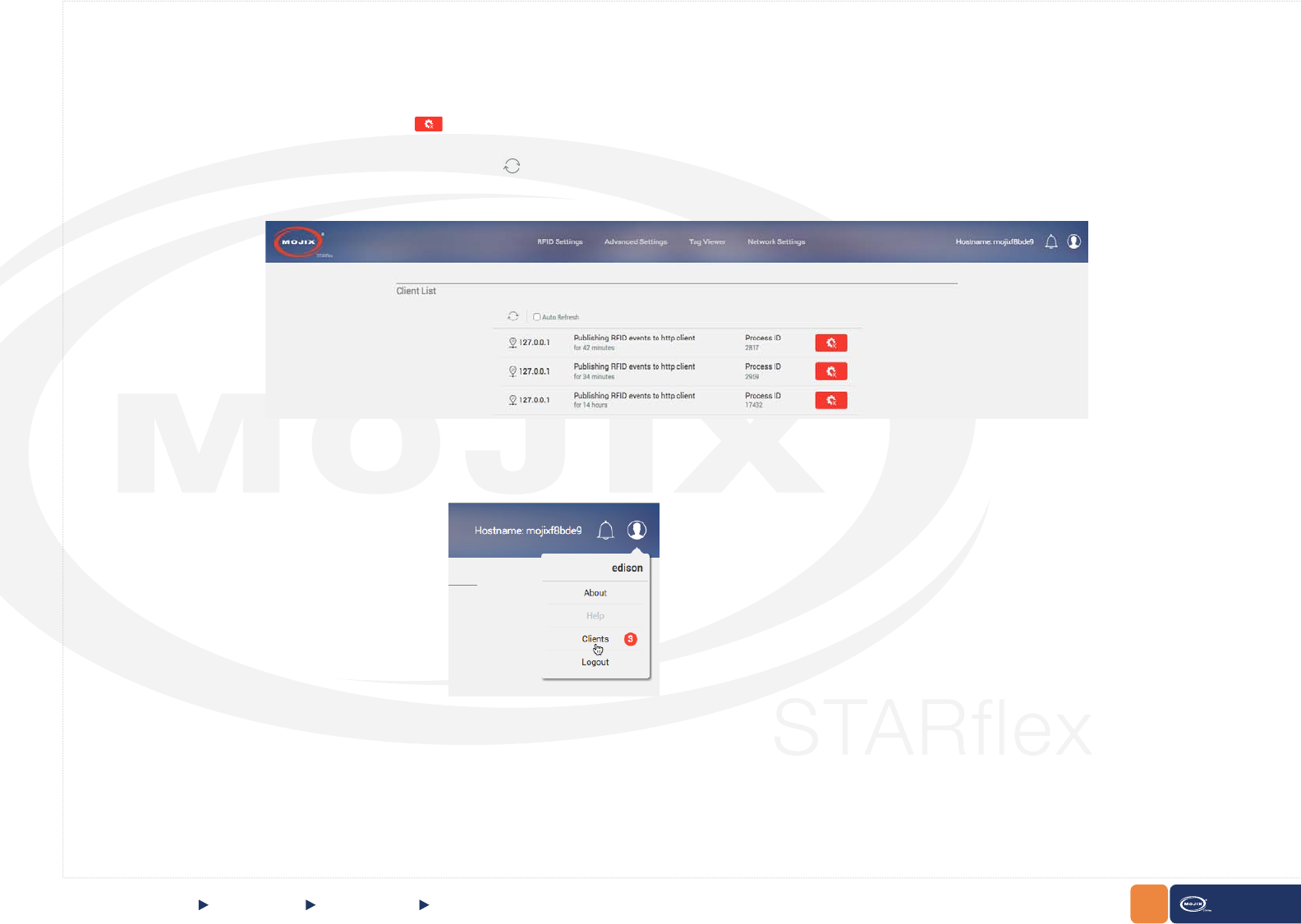
Client List
The client list page displays the information of every client that is connected to the STARex. It includes the IP address, the length of time and the
Process ID of each client.
The user can end the process by using the icon
Refresh manually the list by clicking on the icon option , There is the possibility to auto refresh the client list every 10 seconds by selecting the Auto
refresh option.
The Client List can be also accessed by clicking on the Client option located at the top right hand corner:
QUICK START Advanced Mode Client List
54
CHAPTER II: BASICS STARex MANUAL
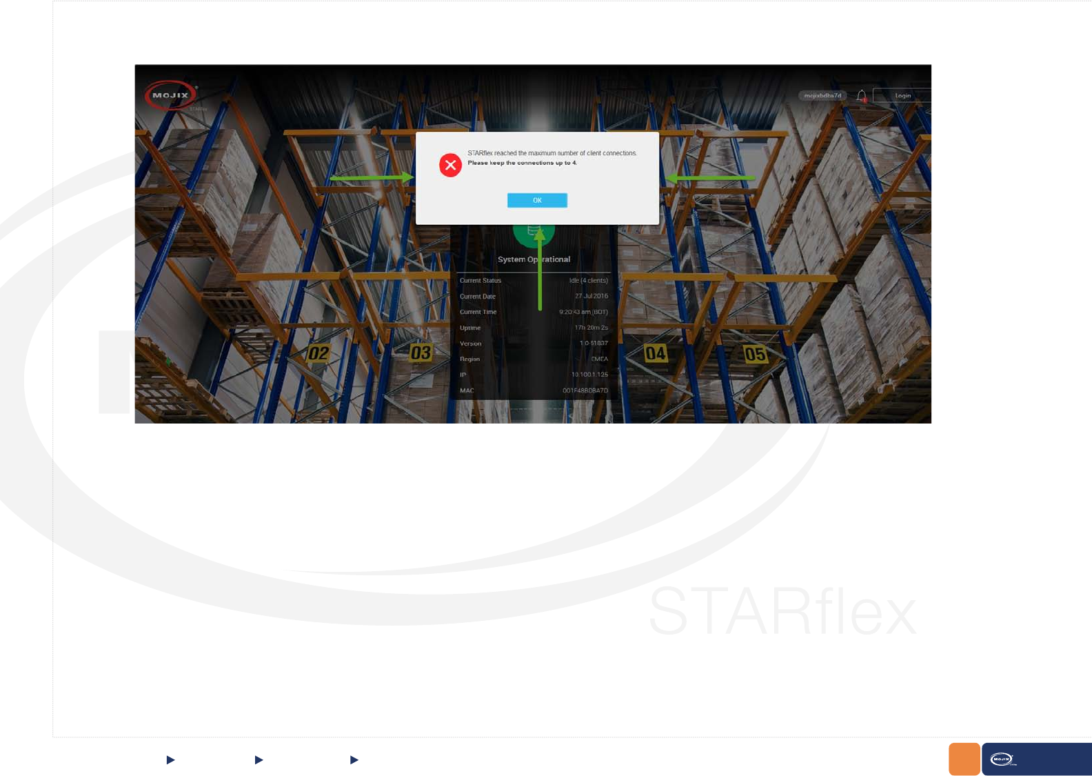
QUICK START Advanced Mode Client List
Note: The maximum number of clients connection is 5 (4 http 1 mqtt). If it is greater than this connection number, the following message will display:
55 STARex MANUAL
RFID SETTINGSCHAPTER III: RFID SETTINGS
3
CHAPTER III:
RFID SETTINGS
3.1 RFID SETTINGS
RFID Settings menu is available after the user logs in to the application with
valid credentials. Once in the RFID Settings page, there are six sections to
congure the antennas, the default values are presented the rst time the
STARex is congured.
56
CHAPTER III: CONTROL STARex MANUAL
RFID SETTINGS
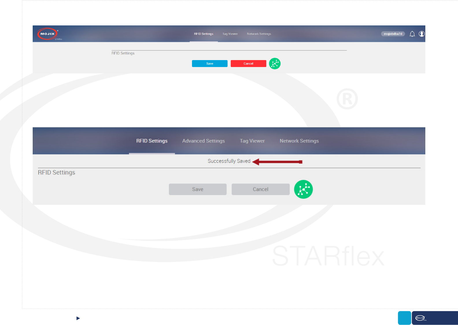
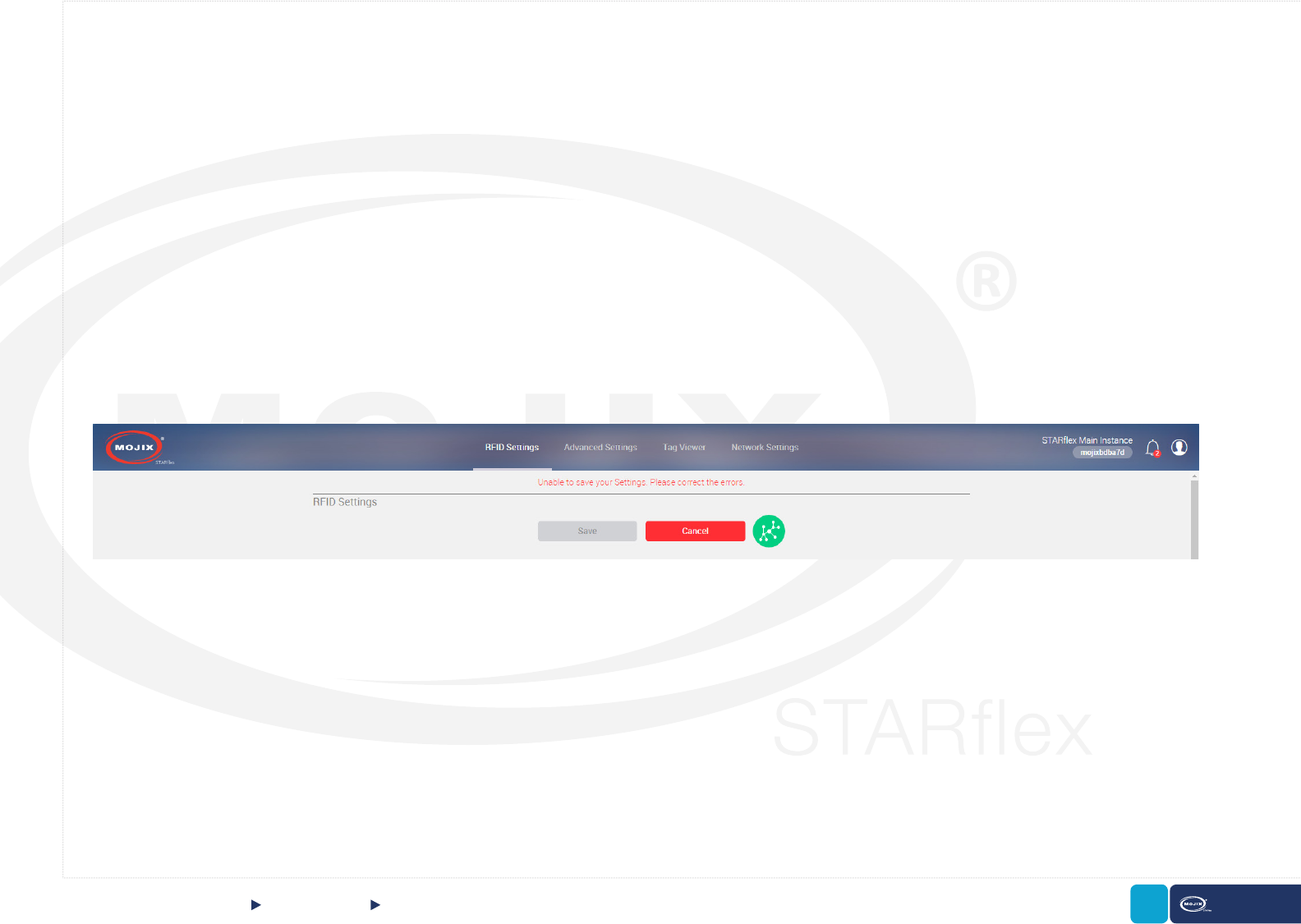
Modications made on any of the conguration sections can be saved by clicking on the Save button and the following message will appear at the top of
the section:
Following nd the description for each one of the RFID Settings sections.
57 STARex MANUAL
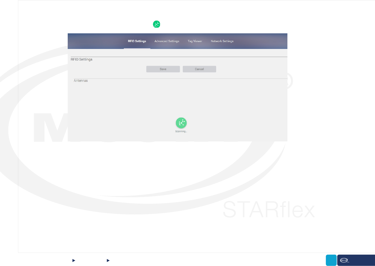
3.1.1 AUTO DISCOVERY
The auto-discovery process is initiated the very rst time a user enters to “RFID Settings” page and every time the user performs a “Default RFID Settings”
and a “Firmware Update”and goes to the page. Click on the icon to start scanning antennas.
RFID SETTINGS Auto DiscoveryCHAPTER III: RFID SETTINGS
Supports Auto-discovery of:
• Direct connected antennas
• eXpanders
• eNodes
• GPIOs
Cannot discover:
• Antennas connected to eXpanders
• Antennas connected to eNodes
• eXpanders connected to eNodes
58 STARex MANUAL
3.1.2 ANTENNAS
In the Antenna section it is possible to select the antennas. There are four antennas available and each can be expanded into four units, making a total
of sixteen antennas. An eXpander can be assigned by checking the “Enable eXpander #” option. The STARex can connect to both options but only one
antenna will transmit at any given time. There is a Clear button displayed at the top right side of this section which resets the antenna selection only.
RFID SETTINGS AntennasCHAPTER III: RFID SETTINGS
3.1.3 ENODE 1 - ENODE 2
In the eNode section, the eNode ID is entered, this eld is editable and when the eNode is not entered, all the related options remain disabled.
A single indicator describes if eXpanders are used. eNodes can be congured as either 4-port devices with antennas attached or as 16-port devices with
eXpanders attached.
The Clear button is displayed at the top right side, this resets the antenna selection.
When an eNode ID is entered and no antennas are selected, after clicking save, an error message is displayed at the top of the page and the entire anten-
nas section is marked to notify the user about the missing conguration. The same behavior is displayed with the eNode sections when no port antennas
are selected. When the eNode ID is not correct, the text eld is marked with an error message below it.
59 STARex MANUAL
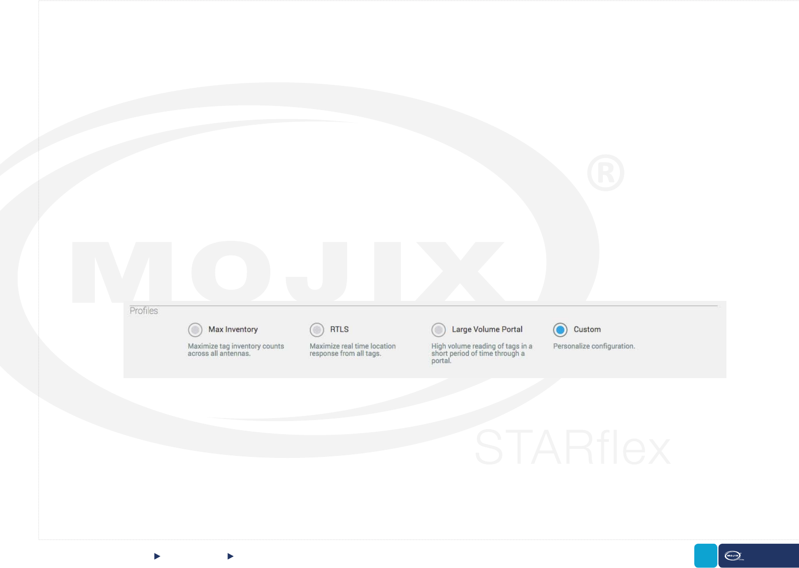
3.1.4 PROFILES
The proles section display four available options, the rst three: “Max Inventory”, “RTLS” and “Large Volume Portal” reect common RFID modes of
operation, the last one “Custom”, allows you to personalize the complete conguration.
- The “Max Inventory” prole conguration, maximize the tag inventory counts across all the antennas. An estimated total number of tags
covered by the STARex’s set of antennas is required. This prole automatically selects the session S2, the target group A, a Q value
calculated according to the estimated number of tags entered, an LF of 256 kHz., a modulation M4 and the selects enabled periodically.
- The “RTLS” prole conguration, maximize real time location response from all tags. An estimated total number of tags covered by the
STARex’s set of antennas is required. This prole automatically selects the session S1, the target group A, a Q value calculated according
to the estimated number of tags entered, an LF of 256 kHz., a modulation M4 and the selects enabled.
- The “Large Volume Portal” prole conguration, read high volume of tags in a short period of time through a portal. An estimated maximum
number of tags that will be moved through the portal is required. This prole automatically selects the session S1, the target group A, a Q
value calculated according to the estimated number of tags entered, an LF of 256 kHz., a modulation M4 and the selects disabled.
- The “Custom” prole conguration, allows the user to personalize the settings. Three sections are enabled selecting this option: “2nd
Receive Antenna Mode”, “Physical Layer Settings” and “Select Pattern”.
RFID SETTINGS ProlesCHAPTER III: RFID SETTINGS

60 STARex MANUAL
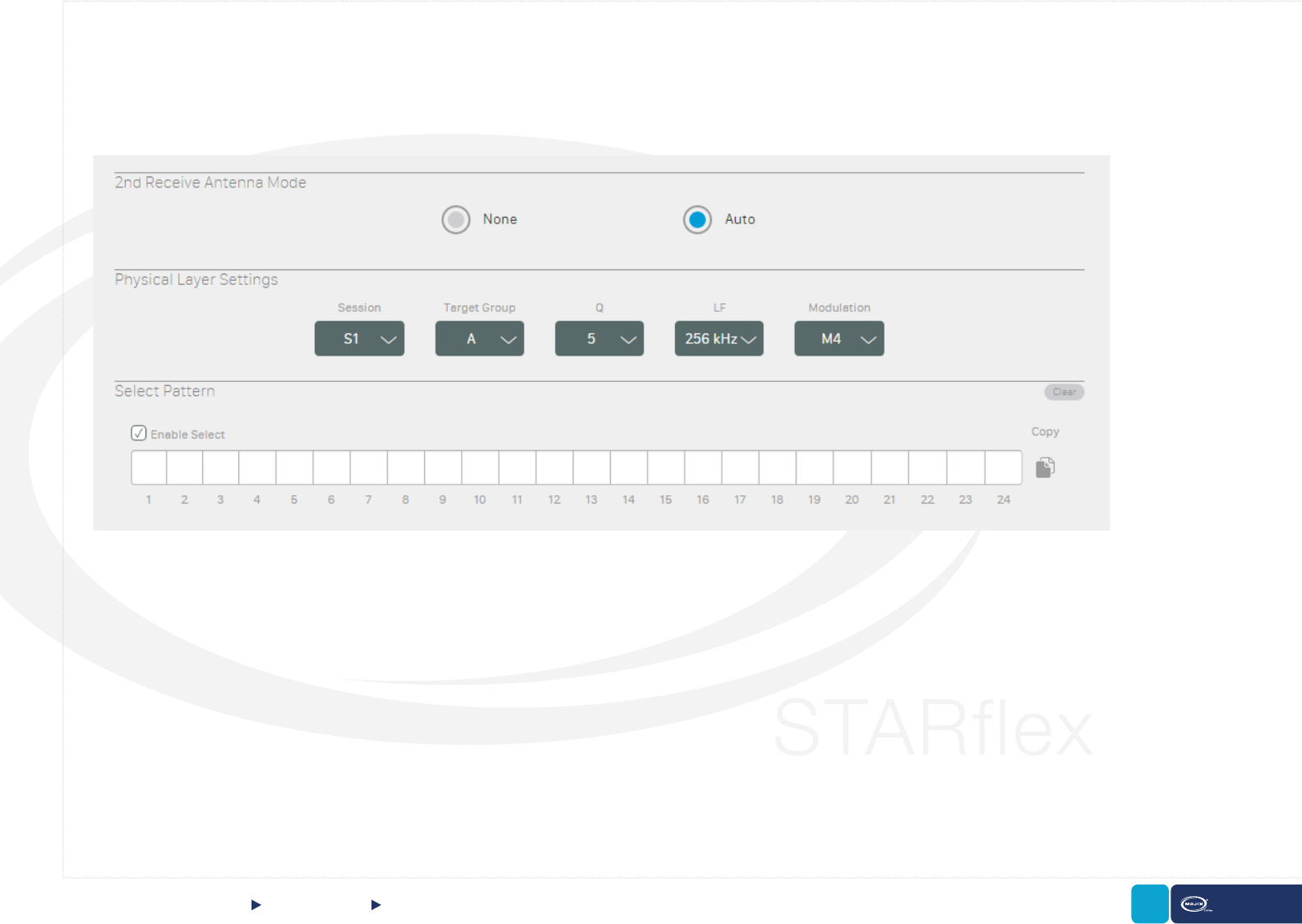
3.1.5 2ND RECEIVE ANTENNA MODE
3.1.6 PHYSICAL LAYER SETTINGS
In this section there are two options available, none and auto:
- None: No 2nd receive antenna.
- Auto: Automatically generated conguration to cycle through all antennas not currently transmitting.
To save the conguration click on the “Save” button, to discard any changes and go back to the last conguration click on the “Cancel” button. The buttons
are at the very top of the page.
This section allows the user to select different options for the physical layer, there are ve combo-boxes available: Session, Target Group, Q, LF and
Modulation.
- Target Group: Default value is A
- Session: Sets the session bit to select and query. Default value is S1.
- Q: Number of slots 2Q. Default value is 5
- LF: Tag backscatter rate. Default value is 256 kHz
- Modulation: Select a Modulation. Available values: M2, M4, M8 and FM0. Default value is Miller-4.
To save the conguration click on the “Save” button, to discard the changes and go back to latest conguration click on the “Cancel” button. Both buttons
are at the very top of the page.
RFID SETTINGS 2nd Receive Antenna Mode & Physical Layer SettingsCHAPTER III: RFID SETTINGS
61 STARex MANUAL
3.1.7 PATTERN
In this menu, the Mask is available to edit if the “Enable Select” option is selected, otherwise the mask is disabled.
Once the mask is enabled, it is possible to select the mask pattern, which is a hexadecimal value representing the bit pattern used to match and select a
subset of the tags EPC number separating this tag from the total tag population.
The beginning of the pattern is always bit position 32, the pointer and length will be auto calculated based on the pattern entered.
RFID SETTINGS Pattern CHAPTER III: RFID SETTINGS
62 STARex MANUAL
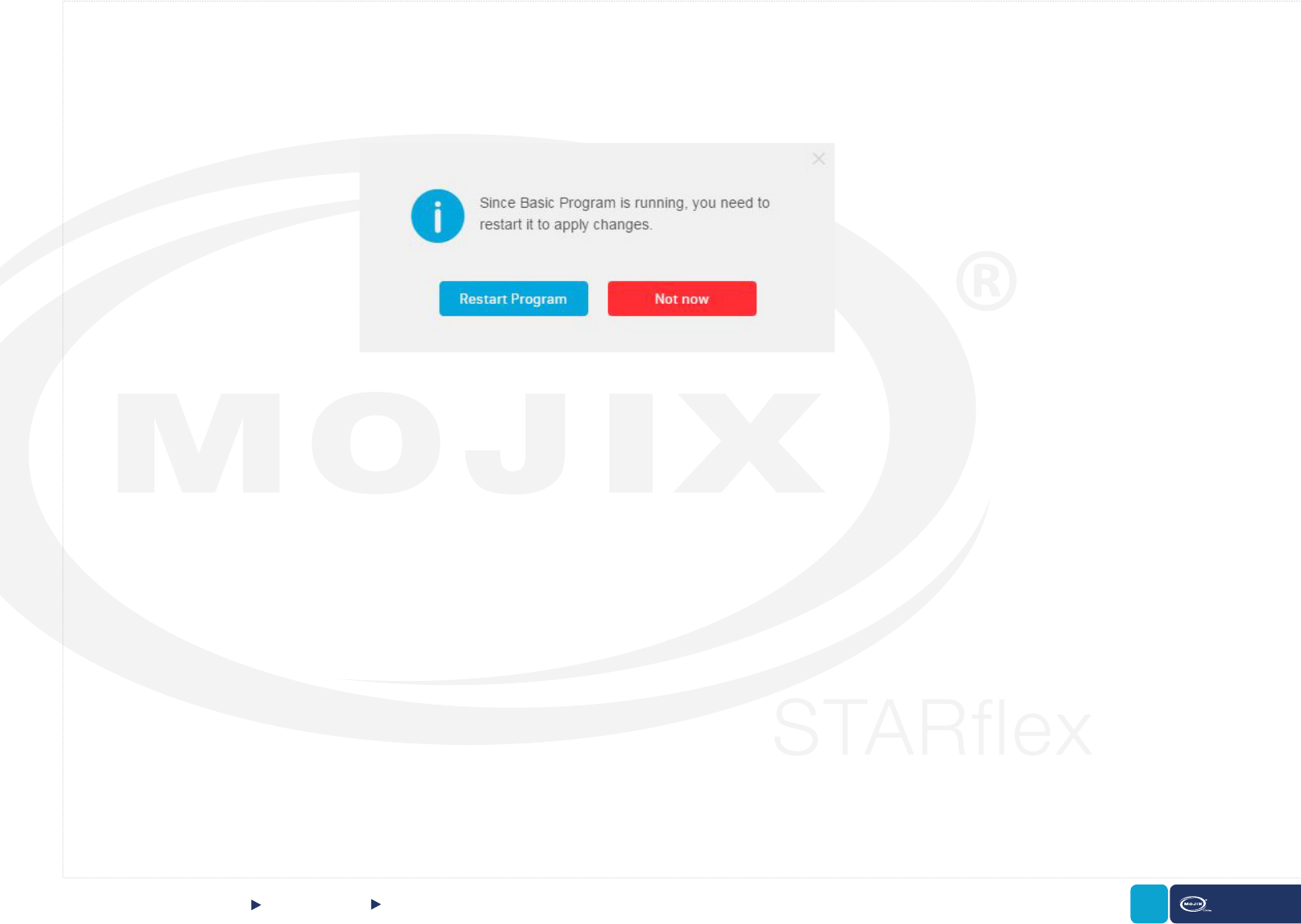
3.1.8 BASIC PROGRAM RUNNING
When the basic program is running (started in the “Tag Viewer” menu) and changes in the RFID settings are done, these are not applied until the readings
are restarted. When pausing the readings, the changes are not applied as only the interface is paused but not the readings in the background. When any
change is saved in RFID settings, a dialog is displayed asking the user to reboot at that moment or later.
RFID SETTINGS Basic Program Running
CHAPTER III: RFID SETTINGS

63 STARex MANUAL
4
CHAPTER IV:
TAG VIEWER
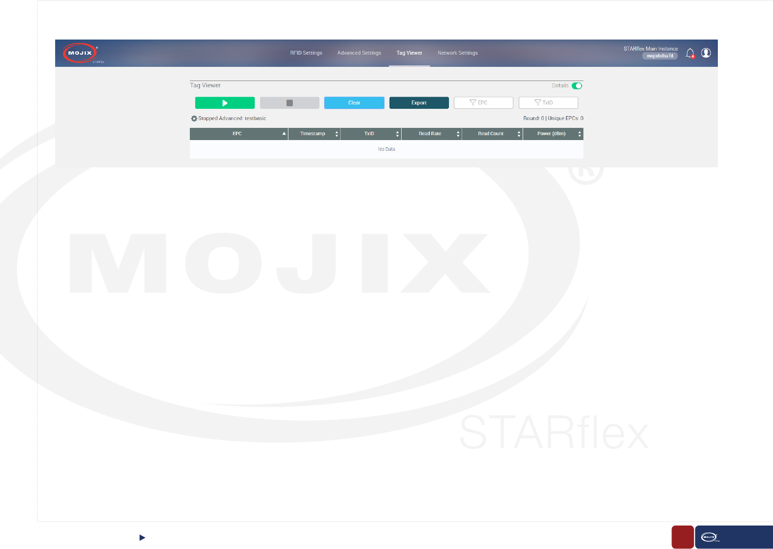
4.1 TAG VIEWER
The tag viewer menu allows the user to quickly select and turn on antennas
in order to nd and read tags, displaying all the tag found results in a list.
In addition, it is possible to lter while live reading the EPCs, TxID (transmit
antenna) and export the list in CSV le.
The Tag Viewer menu is available after the user logs in to the application with
valid credentials. Once in the Tag Viewer menu, the default view is the list in the
simplest mode (EPC, Timestamp, Read Count columns) , without data displayed
or RFID program running.
TAG VIEWERCHAPTER IV: TAG VIEWER
64 STARex MANUAL
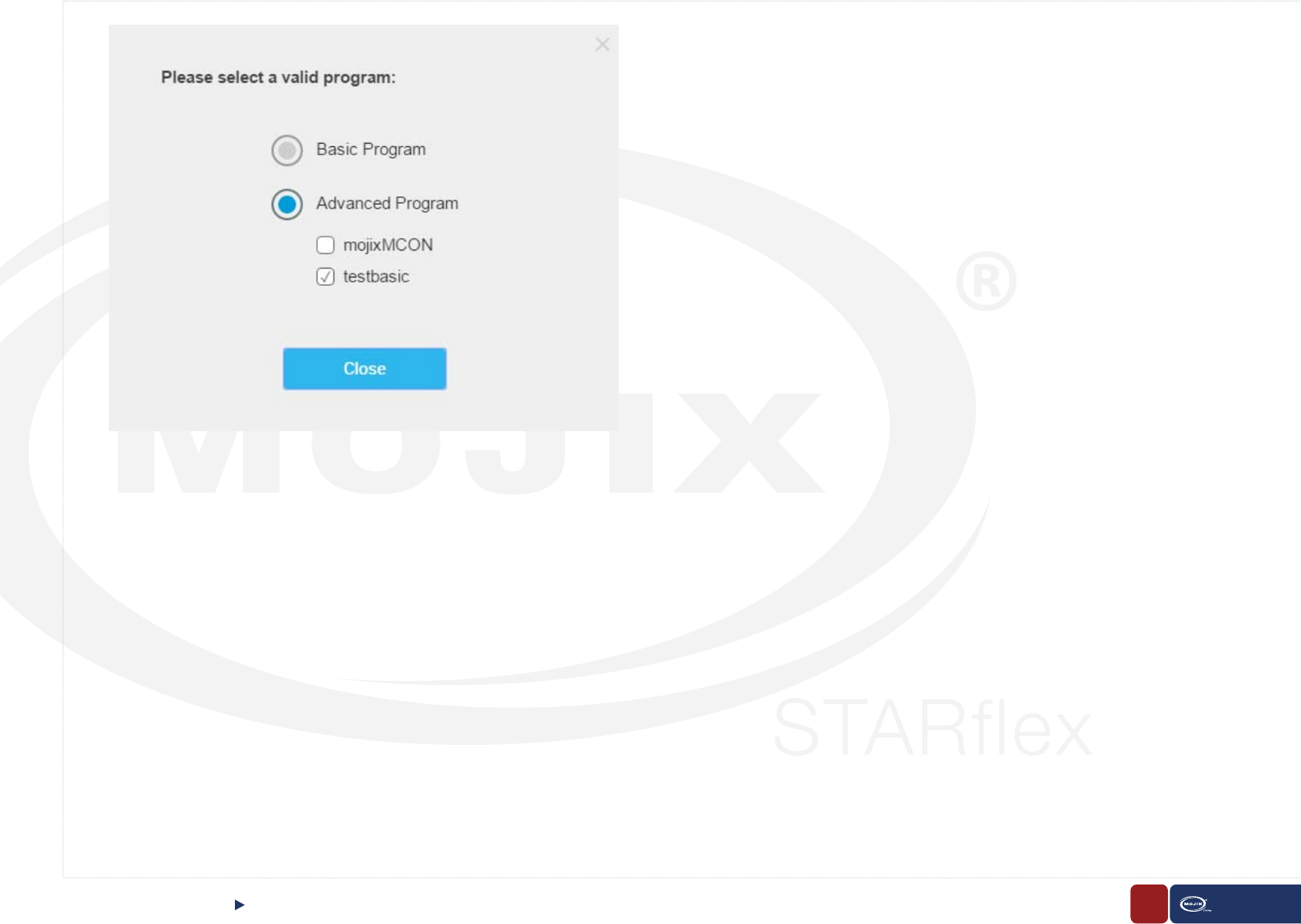
Once the user clicks on the PLAY button (green), the very rst time, a popup window will appear requesting the user to select a valid program before running
the process. The two possible options are “Basic Settings” and “Advanced Settings ” (with a list of available program les).
Basic Settings, which is always available, refers to the basic RFID program that is in the STARex system. In the API document it is also called simpleRFID
program that is overwritten when modifying the RFID settings.
Advanced Settings refers to a RFID programs created in the advanced mode by using the program generation module. There are also RFID programs
created by a 3rd party application such as MCON or VIZIX.
TAG VIEWERCHAPTER IV: TAG VIEWER
65 STARex MANUAL
Once the user selects the RFID program and clicks continue, the selected program is loaded and starts running, meaning the RFID read operation is initiated.
The results will be displayed in simple mode by default, however there is a detailed mode which displays more complex results.
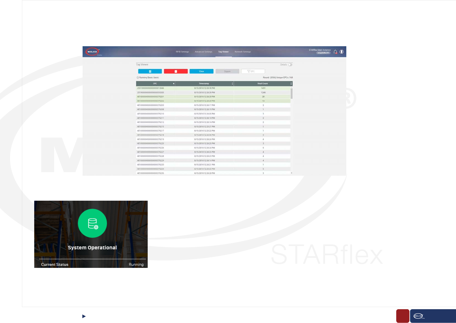
Simple mode view will display one row for EPC tag. The columns for each row shall be EPC , Timestamp, and Read Count. The column Read Count will
display the total number of TagReadData packets that match the EPC.
TAG VIEWERCHAPTER IV: TAG VIEWER
66 STARex MANUAL
TAG VIEWERCHAPTER IV: TAG VIEWER
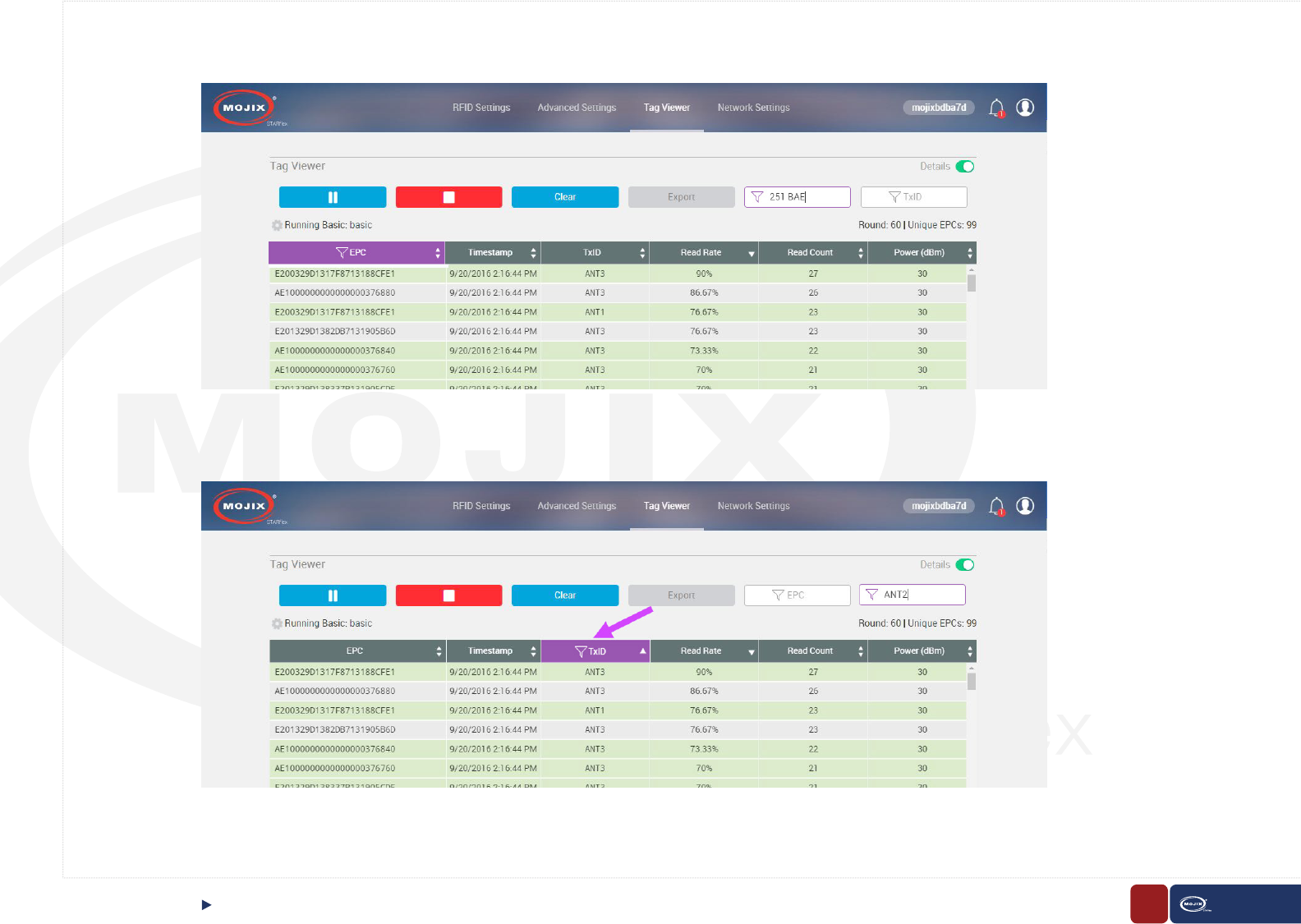
To view the results in Detailed mode, there is a switch at the top right side of the page, once it is enabled the results will be expanded showing one row for
each EPC, tx Antenna Port, tx Expander Port and power tuple. The columns for each row shall be EPC, Timestamp, TxID (transmit antenna), Read Rate
(showed in % is the # of reads / # of read attempts), Read Count, Power.
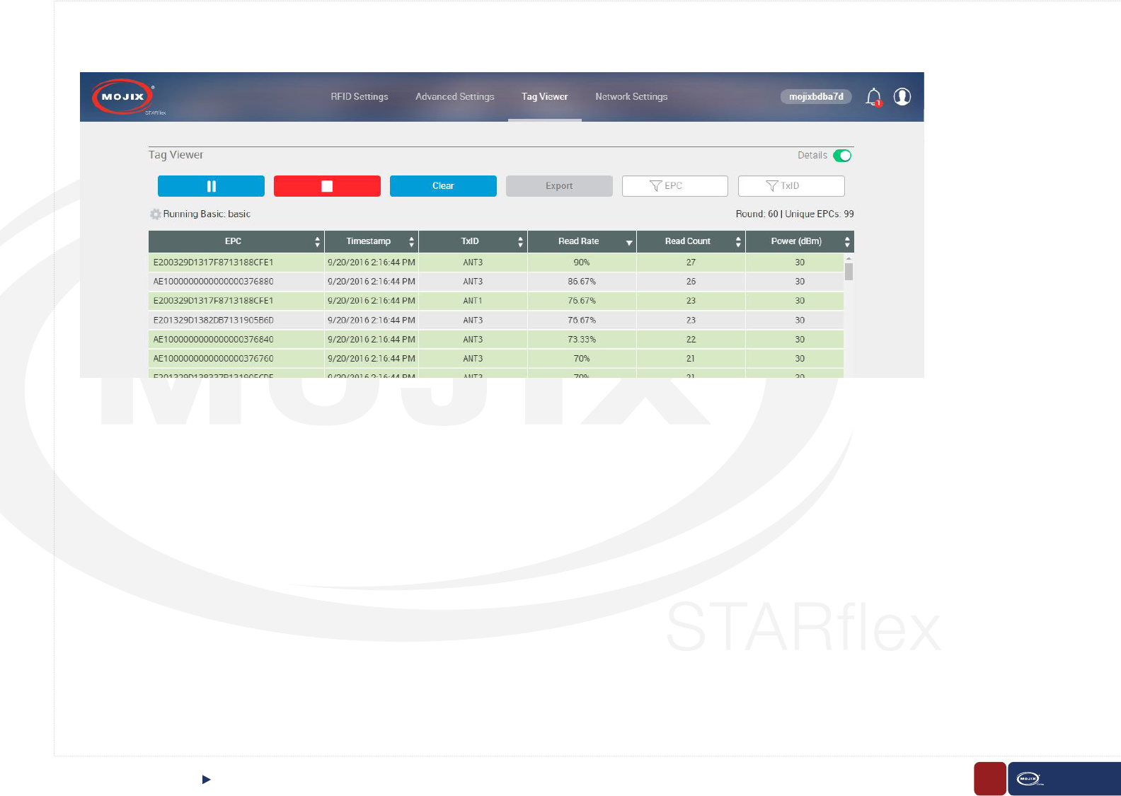
67 STARex MANUAL
When switching between the Simple mode and Detail mode the data will be persistent, the only difference should be the way this data is displayed.
While the process is running and the tags are being read, if the PLAY button (green) is clicked, the color changes to blue and the button becomes a PAUSE button,
the STOP (red) and the CLEAR (blue) buttons are enabled, and the EXPORT button is disabled.
The PAUSE button (blue) pauses the user interface only, the process is still reading the tags in background, once clicked its color changes to green with the PLAY
button replacing the PAUSE one. The STOP (red), CLEAR and EXPORT buttons are enabled
Clicking the STOP button will tell the STARex to stop the RFID reads, it does not close the SSE socket previously opened with GET .../rd/events. If the STARex
were to be subsequently commanded again to start reading tags, tag reads would be immediately delivered via all open SSE sockets.
Clicking on the CLEAR button will clear all the results currently displayed.
The EXPORT button will be enabled only when a program is stopped or paused and it will export all the displayed results at that moment in a CSV le.
Besides the buttons, there are two autocomplete lters, EPC and TxID (only in detailed mode), that while the user is typing, the results will be automatically ltered.
TAG VIEWERCHAPTER IV: TAG VIEWER
68
CHAPTER IV: MAKER STARex MANUAL
TAG VIEWER
Use a single wildcard as “*”, a blank space is a logical “or”: Example: 300 056 searches for pattern 300 or 056. Note that we do not use or as logical or.
In addition, the column, where results are found, will have a distinctive mark:
69
CHAPTER IV: MAKER STARex MANUAL
TAG VIEWER
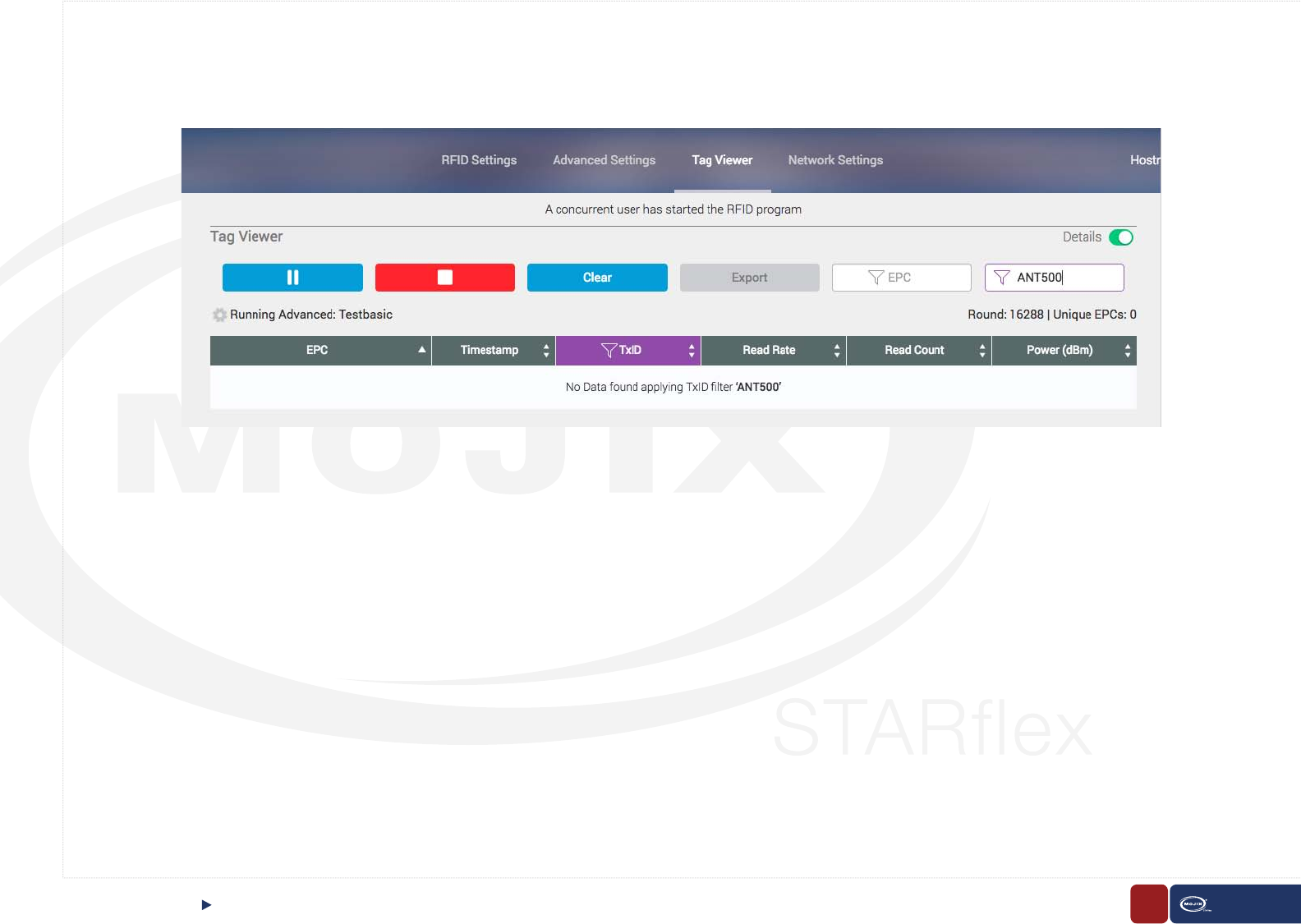
If no results are found the following message will display:
Below the mentioned buttons and above the results table, a code wheel, the number of Rounds and the number of Unique EPCs are displayed.
The Code Wheel allows the user to change the program (Basic and Advanced), it is disabled while the RFID program is running, once the program is
stopped, the code wheel is enabled. The label next to the code wheel shall correspond to the following:
- While running: Running Basic or Advanced: <lename>
- While stopped: Stopped Basic or Advanced: <lename>
- While paused: Paused Basic or Advanced: <lename>
Clicking in the Code Wheel will open a new dialog box and it is possible to change the program between Basic and Advanced. For the advanced settings
there is a list presented with the available program les resident in the STARex.

70 STARex MANUAL
In the results table there is a color code for the tag readings. The default background color is white. When a new tag comes in, it is displayed in a blue
background. The background transitions to white are over 0.5 sec.
When a tag is read but it has been displayed before, this tag is updated in place by painting the background green. The green background fades to white
over 0.5 sec, for a tag that is read much faster than the 0.5 sec, that tag row essentially stays constant green. So it is easy to tell at a glance which tags are
reading well or which tags may be only just reading.
TAG VIEWERCHAPTER IV: TAG VIEWER
71 STARex MANUAL
TAG VIEWERCHAPTER IV: TAG VIEWER
Concurrent users
When different users enter to the Tag Viewer section and START or STOP the tag reading, it is possible for them to see if another user is doing the same
action. A message is displayed notifying that another user has started or stopped the reading and the corresponding buttons (PLAY and STOP) are enabled
or disabled accordingly.
When a user is in the landing page, the current status of the STARex also changes accordingly, if an RFID program is running or not. “Running” will be
displayed if a program is running, “Idle” if not.

STARex MANUAL
72
CHAPTER V: NETWORK SETTINGS
5
CHAPTER V:
NETWORK
SETTINGS
The Network Settings menu is available after the user logs in to the application
with valid credentials. Once in the Network Settings menu, it is possible to con-
gure the STARex to the network that this is going to use. For this the following
elds are available:
5.1 NETWORK SETTINGS
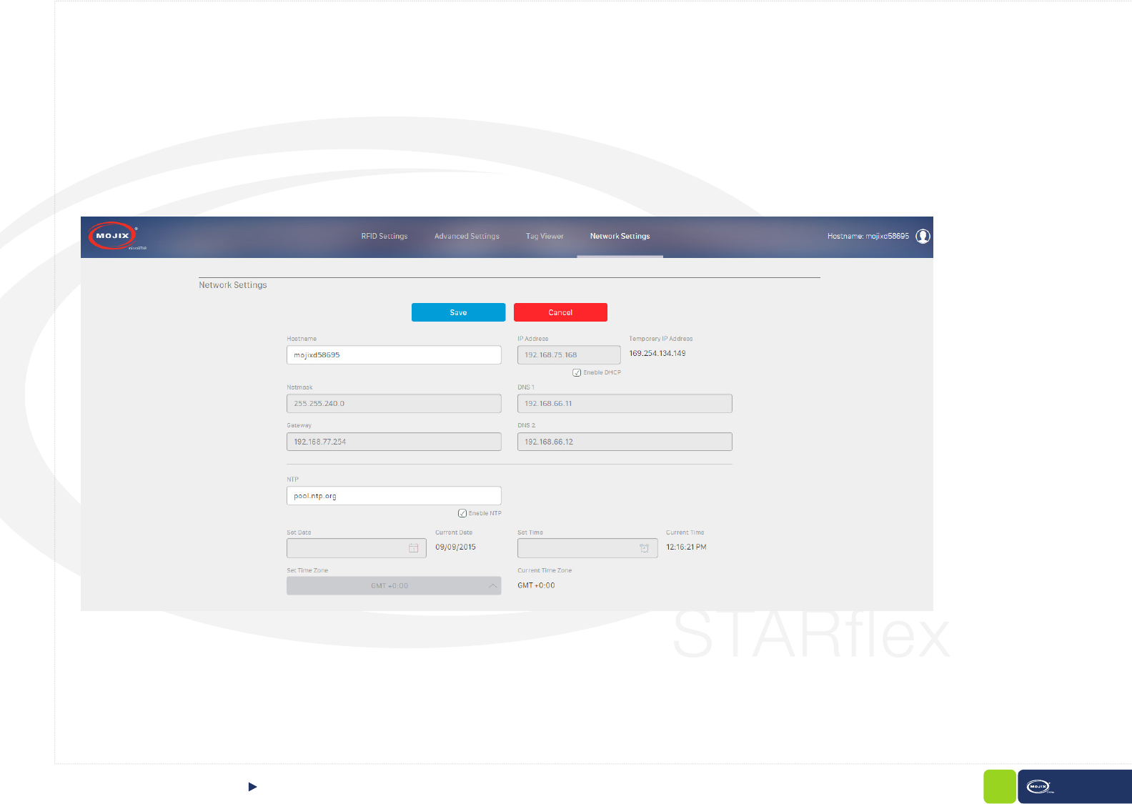
73 STARex MANUAL
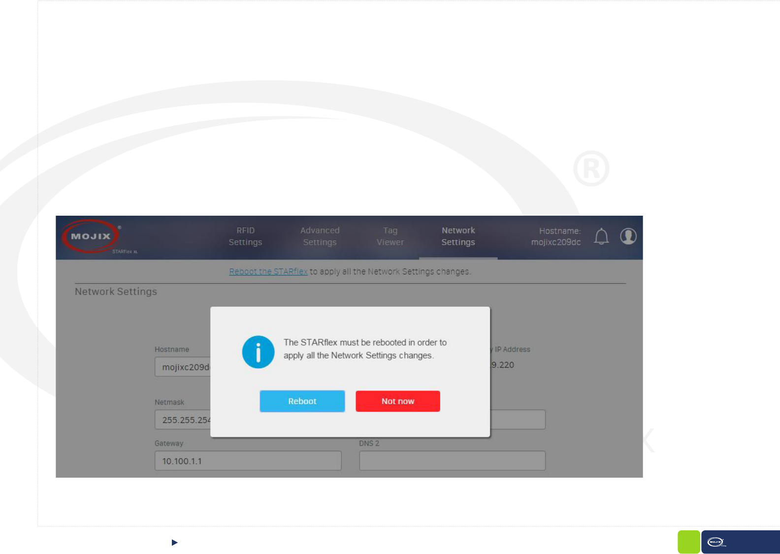
Hostname: Always editable to set the hostname.
DHCP: Three elds for DHCP are available, IP address, netmask and gateway. If the option to enable DHCP is selected, the elds will be disabled and the
corresponding data will be auto populated. If DHCP is disabled, elds will be available to assign manually.
Next to the eld for the IP address there is a label for the temporary IP address which indicates the default IP address of the STARex.
DNS: Two entries for DNSs are available, if DHCP is enabled, these will be disabled with the corresponding data auto populated.
After modifying the hostname, IP address, netmask, gateway, DHCP, or DNS, a reboot of the STARex is required in order to apply the changes, so after
modifying any of these elds a dialog with a message is displayed asking to reboot the STARex. It is also possible not to restart the STARex at the
moment, in that case a message will remain at the top of the “Network Settings” page.
Once the STARex is rebooted, a new tab in the browser is displayed with the STARex available and the new network values set. In case your new IP
address or hostname is unreachable, it is necessary to check your conguration manually or contact your IT personnel.
CHAPTER V: NETWORK SETTINGS NETWORK SETTINGS
74 STARex MANUAL
NTP: Single entry for NTPs is displayed and available to edit only when the option “Enable NTP” is selected.
If NTP is enabled the elds “Set Date” and “Set Time” will be disabled.
Date, Time & Timezone: A eld to set the date, time and timezone are available. The elds display the user’s machine date, time and timezone by default.
Clicking on the “Set Date” eld a datepicker is displayed in order to choose the date. Clicking on the “Set Time” eld a time picker is displayed in order to
choose the time for the STARex.
There are labels to show the current date, time, and time zone, the labels show the current values congured in the STARex. These values are the same
as the ones displayed in the landing page.
CHAPTER V: NETWORK SETTINGS NETWORK SETTINGS
STARex MANUAL
75
CONTROLCHAPTER VI: CONTROL
6
CHAPTER VI:
CONTROL
6.1 CONTROL
In order to access to the Control menu, the user must be logged into the appli-
cation, after that the user must select “Advanced Mode” option and provide the
password to have the advanced mode option visible in the menu, once visible and
click on it, a group of options will be displayed including “Control”.
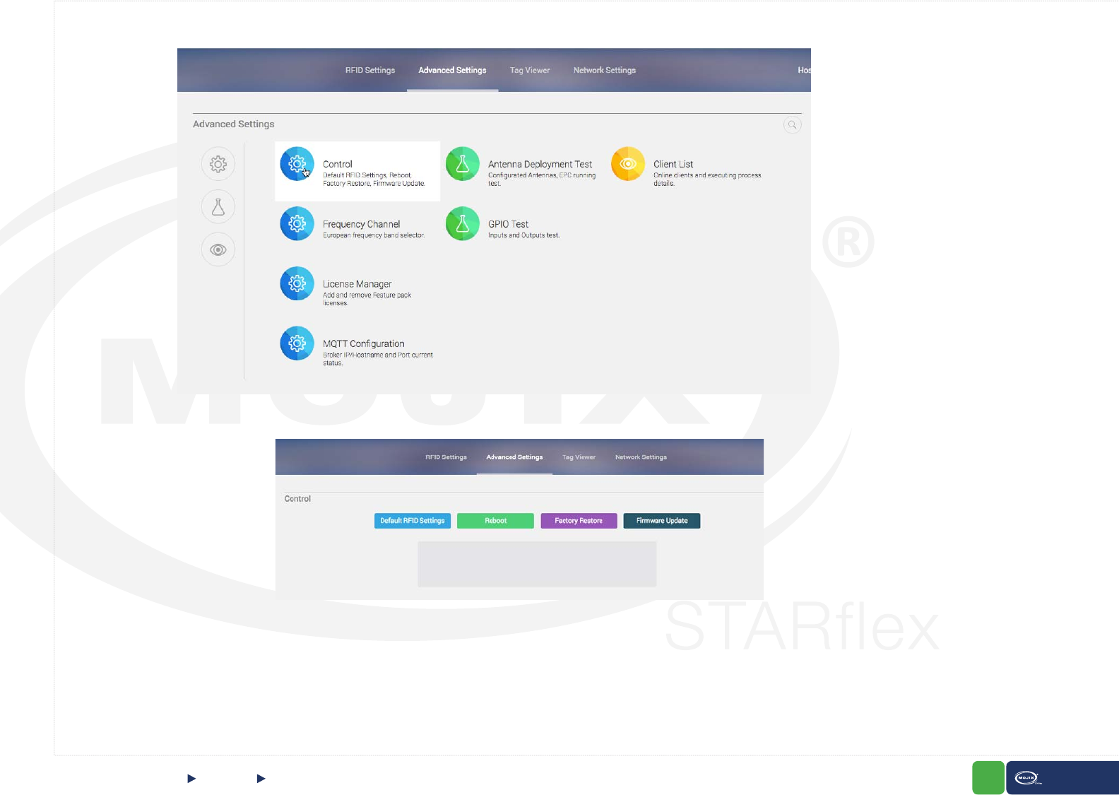
76 STARex MANUAL
Once in the Control page, there are four visible buttons, Default RFID Settings, Reboot, Factory Restore and Firmware Update
6.1.1 DEFAULT RFID SETTINGS
CONTROL Default RFID SettingsCHAPTER VI: CONTROL
Once this option is clicked and after conrming the action, the application will reset all the RFID settings in both the basic and advanced pages to a known
default conguration.
77 STARex MANUAL
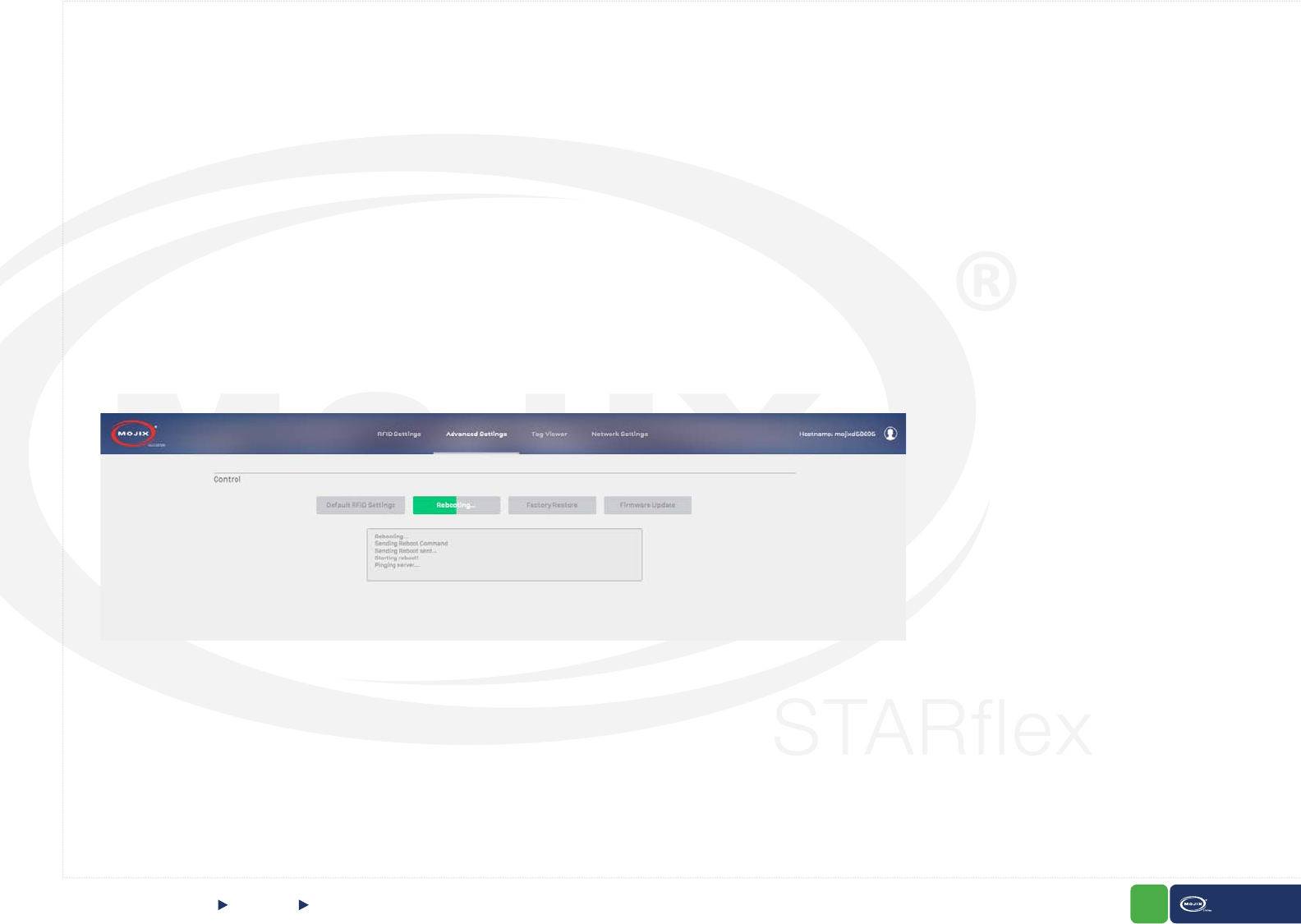
6.1.2 REBOOT
6.1.3 FACTORY RESTORE
This option allows the user to reboot the STARex, the result notication messages are displayed in the area below the buttons.
This option allows the user to restore the STARex back to its original conguration (the one given in the manufacturing) including all the default network
settings and default name. The notication messages are displayed in the area below the buttons.
Important. Once the reboot is done, any of the changes in the RFID Settings page (simpleProgram conguration) will be saved.
Any subscription running at the moment is stopped, it is needed to start it again after the update process.
CONTROL Reboot & Factory RestoreCHAPTER VI: CONTROL
The Basic mode default settings are:
- No eXpanders enabled.
- 2nd receive antenna set to Auto.
- Physical Layer Defaults:
- Target Group: A
- Session: S1
- Q: 5
- LF: 256 kHz
- Modulation: Miller-4
- Selects enabled and NO mask
78 STARex MANUAL
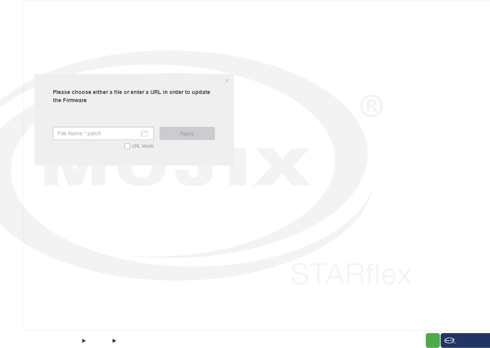
6.1.4 FIRMWARE UPDATE
Once clicked this option, a new dialog will be displayed asking for the le to update the Firmware. In this new dialog a folder icon is displayed, it will launch
the le picker in order to select the corresponding le. Additionally, the option “URL Mode” is available allowing to enter the URL where the le is located
and download it to the current machine.
After choosing the le and clicking “Apply”, the current dialog is closed and the application uploads the le, however before the process starts, the RFID
program is stopped. Once it is done, the corresponding upgrade process starts and after the process completes, a reboot of the STARex is done. The
notication messages will be displayed in the area below the buttons.
CONTROL Firmware UpdateCHAPTER VI: CONTROL
Important. Upon a rmware update any subscription running at the moment is stopped, it is needed to start again after the update process.
In IOS devices the “locations” to upload attachments are set up by third party applications, by default only the Photo Album contents are selectable.
By having third party applications such as DropBox, Google Drive, you can have other locations from where you could choose the le for rmware update. We
have similar behavior for Android devices.
Works on IOS version 9.0 or higher, you will have to install other third applications for versions earlier than 9.0 in your IOS device.
79 STARex MANUAL
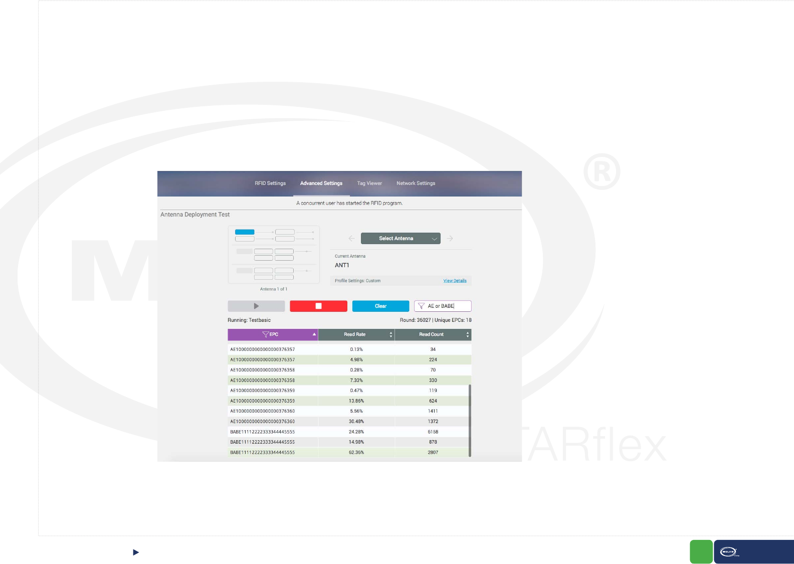
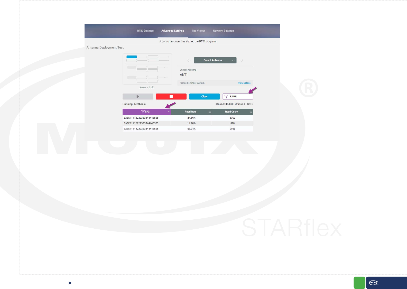
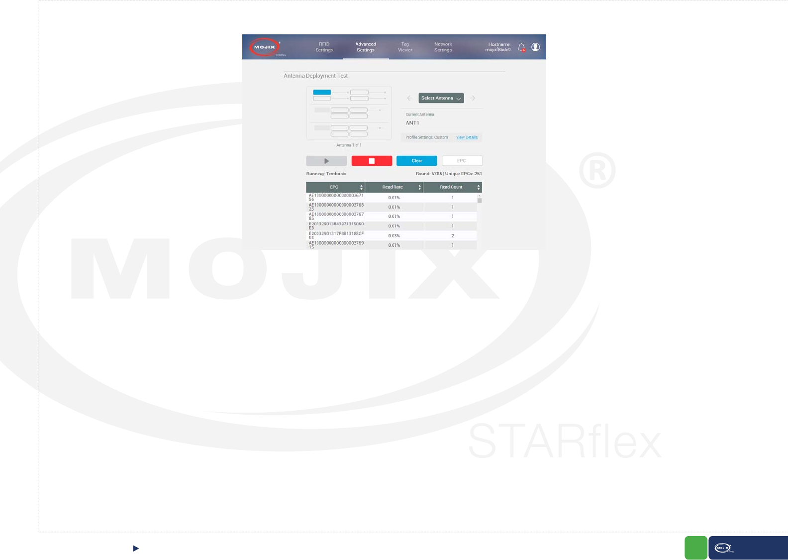
6.2 ANTENNA TEST
The “Antenna Deployment Test” page allows the user to step through the congured antennas in the basic settings page (refer to Chapter III - RFID Settings) in order
to test them one by one and make sure they each can read tags. This process ensures proper continuity of cables and antennas.
In this page, a map is displayed, giving an overall view of the conguration showing all the antennas and highlighting the antenna that is tested at the moment. In order
to select the antennas there are 2 arrows next to the map which allows to go through all of them, in addition the name of the antenna selected is displayed.
A section with the prole settings is available to show and hide by clicking on the “View details” link
Below, the buttons to Start, Stop and Clear the list of read tags are displayed and next to them an “EPC” lter.
Use a single wildcard as “*”, a blank space is a logical “or”: Example: 300 056 searches for pattern 300 or 056. Note that We do not use or as logical or.
ANTENNA TESTCHAPTER VI: CONTROL
80 STARex MANUAL
CHAPTER VII: CONTROL
In addition, the column where results are found and the EPC lter text area will have a distinctive mark:
ANTENNA TEST
Moreover, the number of Rounds, number of unique EPCs and the name of the program that is currently running are displayed.
At the end of the page a list with the tag reads is available with 3 columns: EPC, Read Rate and Read Count.
If there are no antennas selected in the basic settings page, a message should be displayed at the top of the page. In addition, the map, arrows, name of the antennas,
power and the buttons (Play, Stop and Clear) are disabled.
If the program is started from the “Antenna Deployment Test” page, any program running at the moment in the “Tag Viewer” is stopped and right after that the “Testba-
sic” program (advanced) starts running. However, if the basic program or any other (except Testbasic) is started from the “Tag Viewer”, the Antenna Deployment Test
remains stopped.
81 STARex MANUAL
ANTENNA TESTCHAPTER VII: CONTROL
82 STARex MANUAL
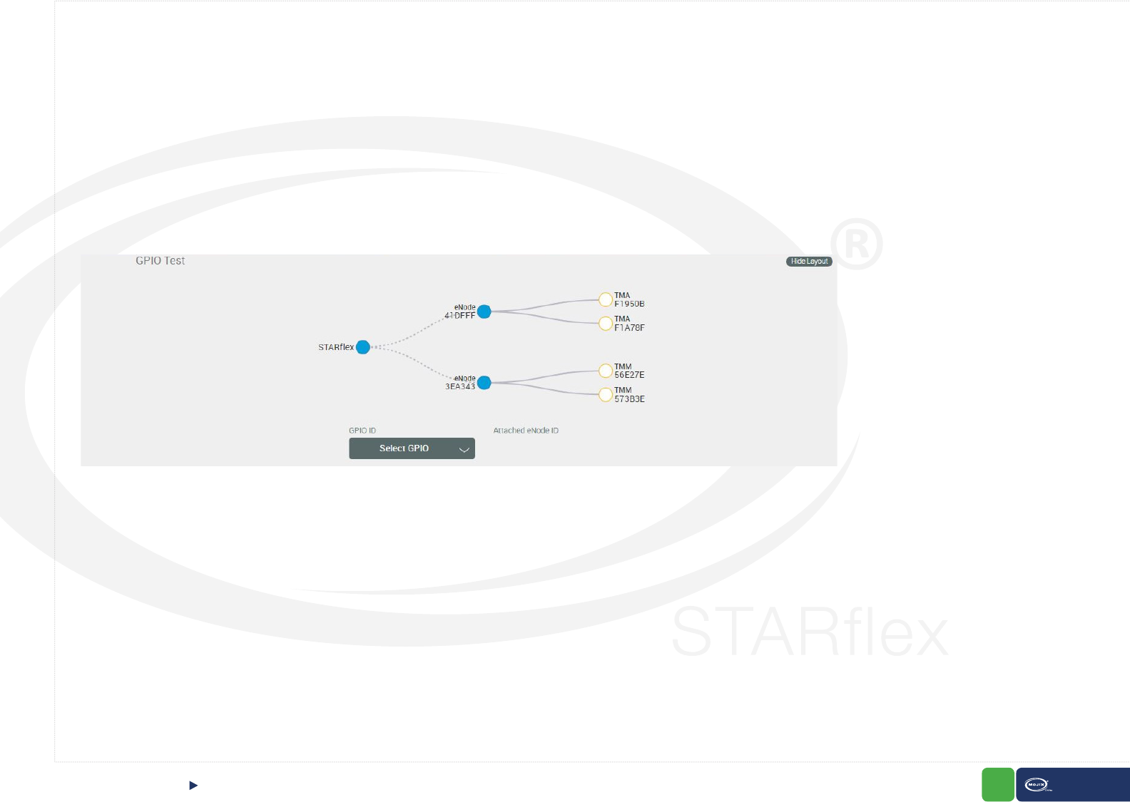
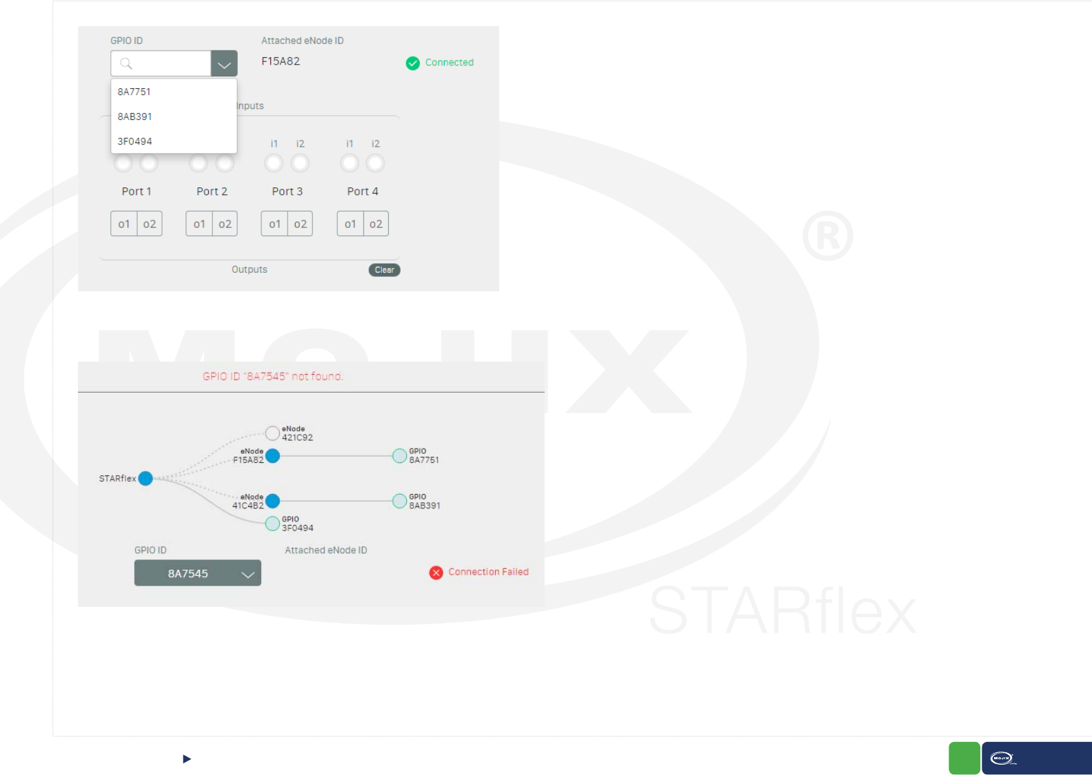
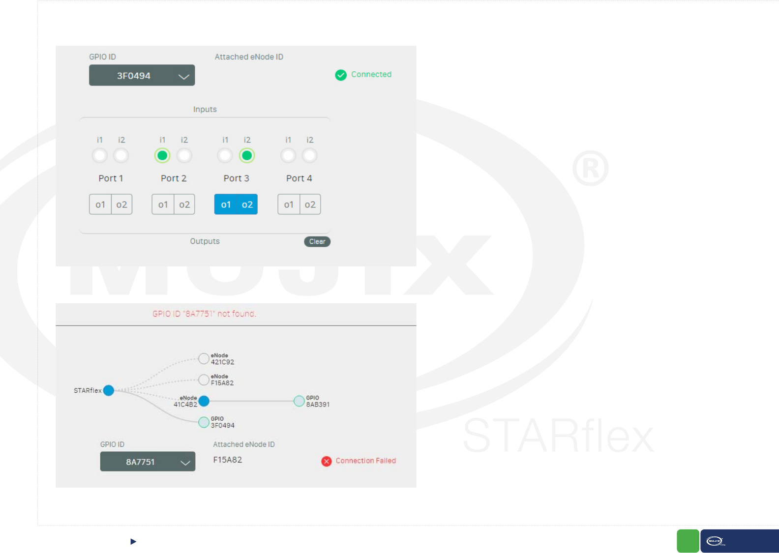
6.3 GPIO TEST
The “GPIO Test” page allows the user to validate the state of connected input devices and to test output devices by triggering the respective output through the interface.
Once in the page, the GPIO IDs and eNodes are auto discovered and displayed in a tree showing the current conguration.
The tree allows the user to select and connect the GPIOs, expand or collapse the eNodes, zoom in or zoom out and move the whole tree. Once a GPIO is selected, the ID
and the eNode (if it is attached to an eNode) are populated in the corresponding combo-box and label below. In the same way if a GPIO is selected from the combo-box,
the change is reected in the tree.
A dotted line is displayed from the STARex node to the eNodes and a straight line from the eNode to GPIO.
Congurations that include Turbo Mux or Turbo Antenna will have the possibility to see the connection here as well, a straight line from an eNode to the corresponding
Turbo Mux or Turbo Antenna will be displayed.
It is possible to select the GPIO IDs from the combo-box or typing in the GPIO ID eld and being helped with the auto complete functionality. If the ID is not in the list, it is
also possible to add it as new.
GPIO TESTCHAPTER VI: CONTROL
Important. The GPIO ID selected remains connected for the current session.
83 STARex MANUAL
A green ok icon is displayed when the entered GPIO ID is valid. In case the ID is invalid or is not connected to the unit, a red X icon is displayed.
If the GPIO is attached to an eNode, the corresponding ID is populated right next to the GPIO ID.
GPIO TESTCHAPTER VI: CONTROL
84 STARex MANUAL
With a valid GPIO ID, the state of the connected input devices is reected in the corresponding input and port, the output buttons are enabled to trigger the respective
output devices through the interface.
If an output device is unplugged from the GPIO and the corresponding button is clicked, an error message is displayed.
GPIO TESTCHAPTER VI: CONTROL
85 STARex MANUAL
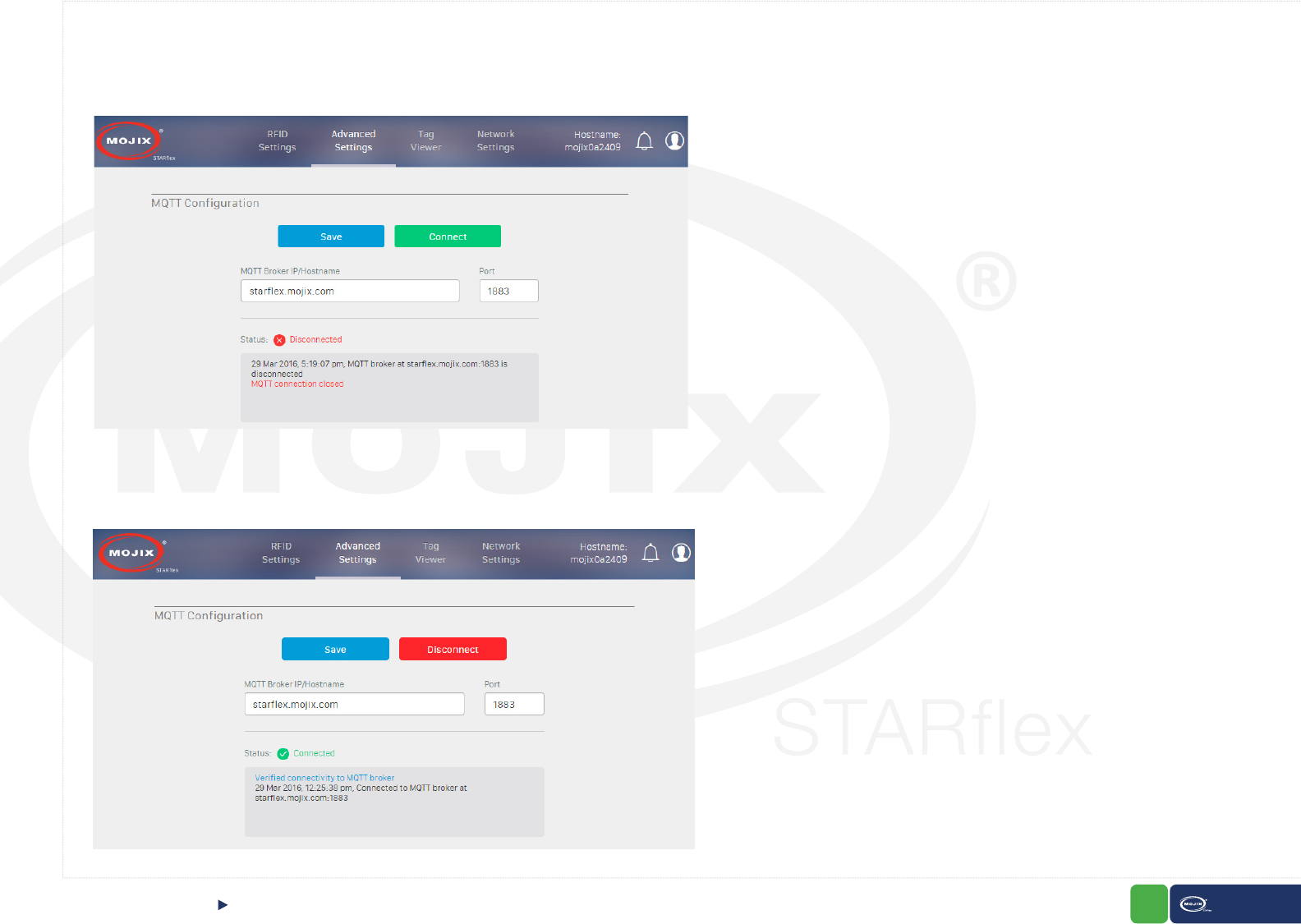
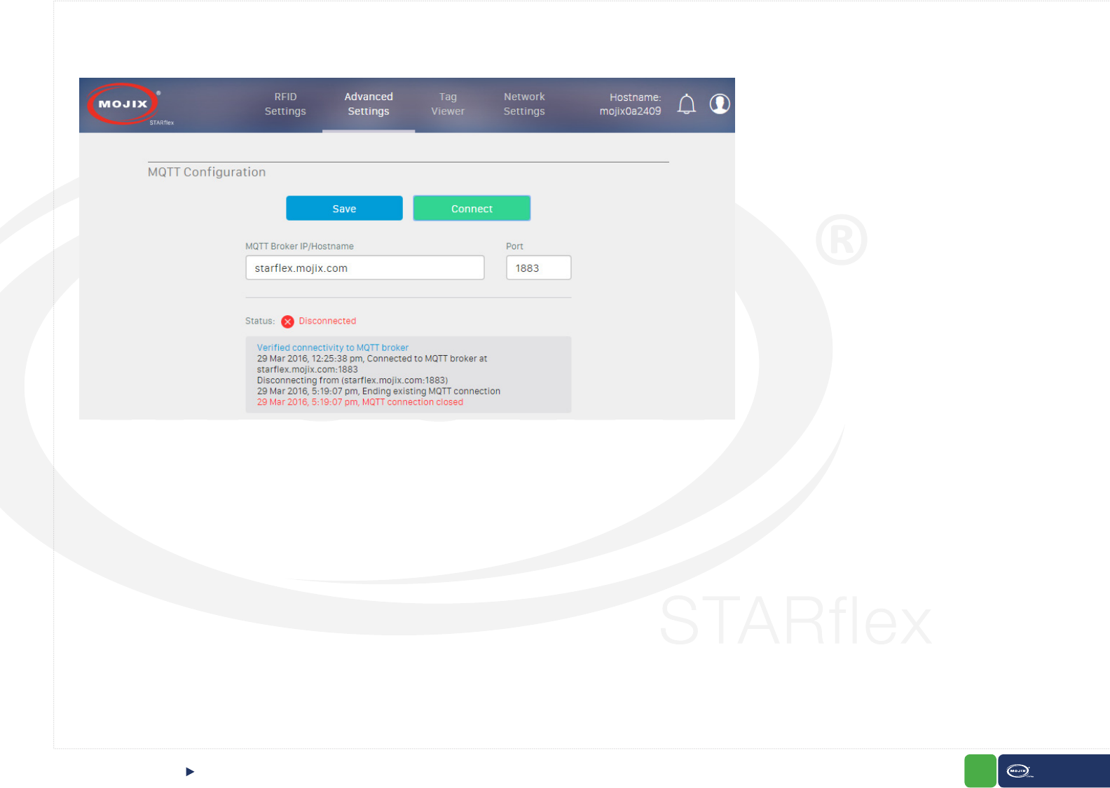
6.4 MQTT CONFIGURATION
The “MQTT Conguration” page allows the user to set up the hostname/IP address, port to connect and test to the MQTT broker.
The “Save” and “Connect” buttons are enabled once the MQTT broker IP and port are entered.
With the “Connect” option it is possible to connect to the MQTT broker without saving the information and with the “Save” option the data to connect to the
MQTT Broker is saved.
After the MQTT broker is connected, the label of the “Connected” button turns to “Disconnect” and this option disconnects the STARex from the MQTT broker.
MQTT CONFIGURATIONCHAPTER VI: CONTROL
86 STARex MANUAL
If the connection is successful, the status “Connected” and a green ok icon are displayed, otherwise the status “Disconnected” and a red error icon are shown.
In addition, in the rectangular section displayed below, all the MQTT related messages regarding the connection are displayed.
MQTT CONFIGURATIONCHAPTER VI: CONTROL
87 STARex MANUAL
LICENSE MANAGERCHAPTER VI: CONTROL
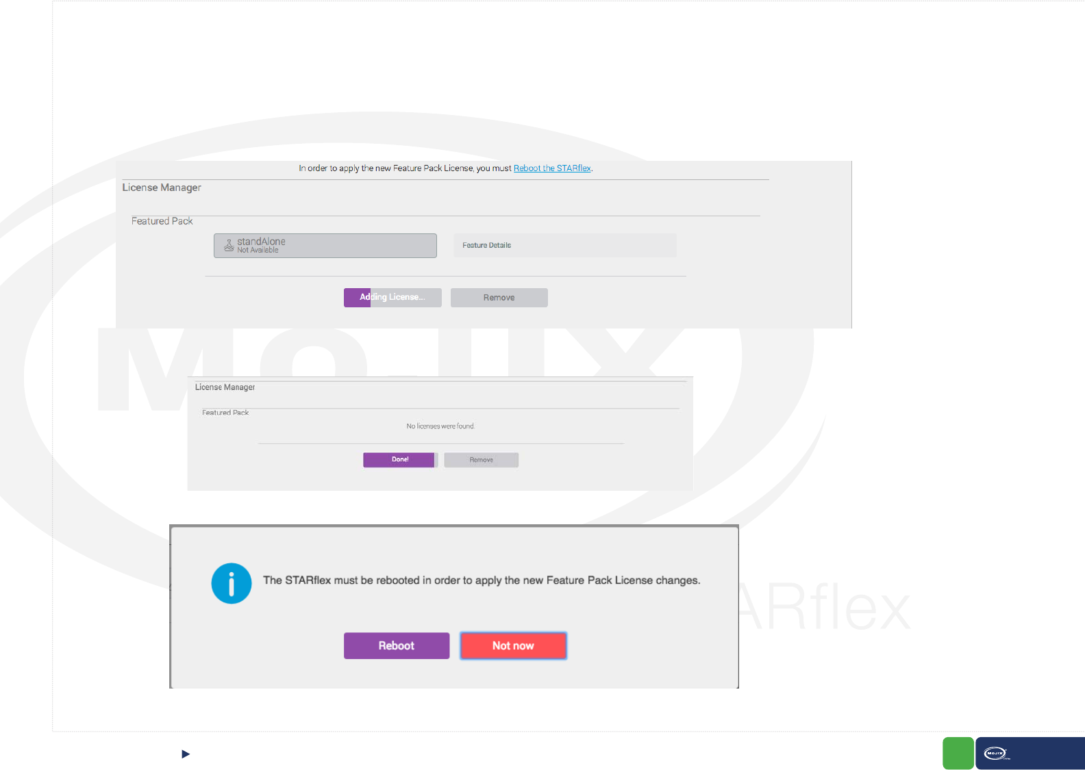
6.5 LICENSE MANAGER
The “License Manager” page allows the users to upload and add or remove licenses to the STARex.
To upload a new license click on “Add License” button, with the le picker select the corresponding license and apply. A loading indicator will appear while the license is
uploading:
The license will be successfully uploaded when the button changes to Done!
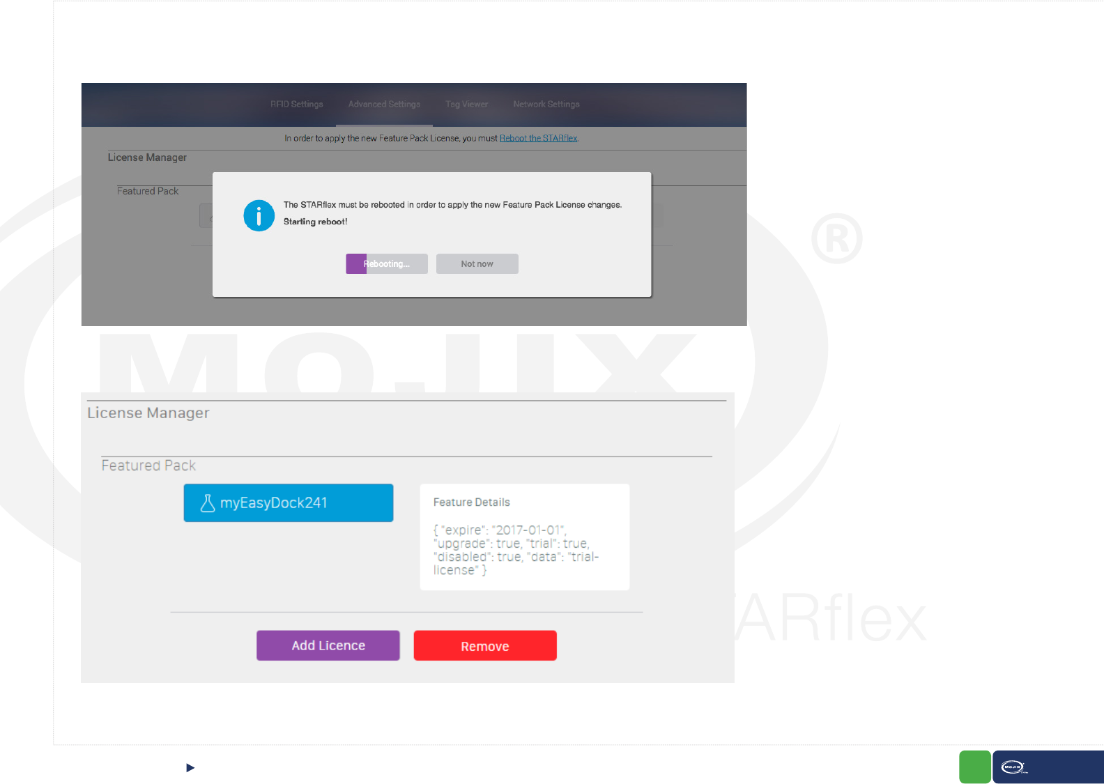
Click on the Reboot button in order to apply the new License:
88 STARex MANUAL
LICENSE MANAGERCHAPTER VII: CONTROL
The reboot process will be automatically displayed:
After the reboot is completed the license is displayed as available. The feature details can be displayed by clicking on it.
89 STARex MANUAL
CHAPTER VII: CONTROL
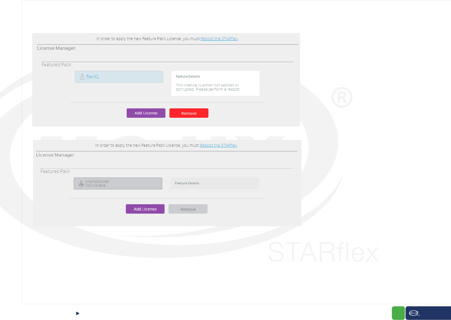
Invalid licenses are listed and visible however these are disabled.
To remove a license click on it and click on “Remove”, it remains displayed but not available, a reboot is required for valid licenses in order to remove them completely.
In IOS devices the “locations” to upload attachments are set up by third party applications, by default only the Photo Album contents are selectable.
By having third party applications such as DropBox, Google Drive, you can have other locations from where you could choose the le for license manager. We have
similar behavior for Android devices.
Works on IOS version 9.0 or higher, you will have to install other third applications for versions earlier than 9.0 in your IOS device.
LICENSE MANAGER

90 STARex MANUAL
CHAPTER VII: APPENDIX FCC Notice, STARex and eNode
APPENDIX
FCC Notice, STARex and eNode
CAUTION: To comply with FCC RF exposure compliance requirements, a separation distance of 20 cm must be maintained between the antenna of this
device and all persons.
WARNING: This equipment has been tested and found to comply with the limits for Class A digital device pursuant to Part 15 of the FCC Rules. These limits are designed
to provide reasonable protection against harmful interference when the equipment is operated in a commercial environment. This equipment generates, uses, and can
radiate radio frequency energy and, if not installed and used in accordance with the instruction’s manual, may cause interference to radio communications. Operation of
this equipment in a residential area is likely to cause interference in which case the user will be required to correct the interference at his own expense. However, there
is no guarantee that interference will not occur in a particular installation. If this equipment does cause harmful interference to radio or television reception, which can be
determined by turning the equipment off and on, the user is encouraged to try to correct the interference by one or more of the following measures:
· Reorient or relocate the receiving antenna.
· Increase the separation between the equipment and receiver.
· Connect the equipment into an outlet on a circuit different from that to which the receiver is connected.
· Consult the Mojix Professional Services organization.
In order to ensure compliance with FCC regulations, shielded and grounded cables must be used with this equipment. Operation with non-approved equipment or
unshielded cables is likely to result in interference to radio and TV reception. The user is cautioned that changes and modications made to the equipment without the
approval of the manufacturer could void the user’s authority to operate this equipment.