MOJIX STAR1000C RFID Reader User Manual MojixBody1
MOJIX, Inc. RFID Reader MojixBody1
UserManual.wiki
>
MOJIX
>
STAR1000C User Manual
Users Manual
Navigation menu
Upload a User Manual
Namespaces
Wiki Guide
HTML
PDF
Info
Views
User Manual
Discussion / Help
Navigation
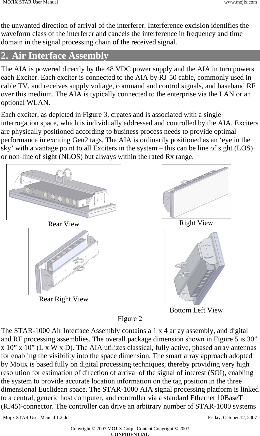
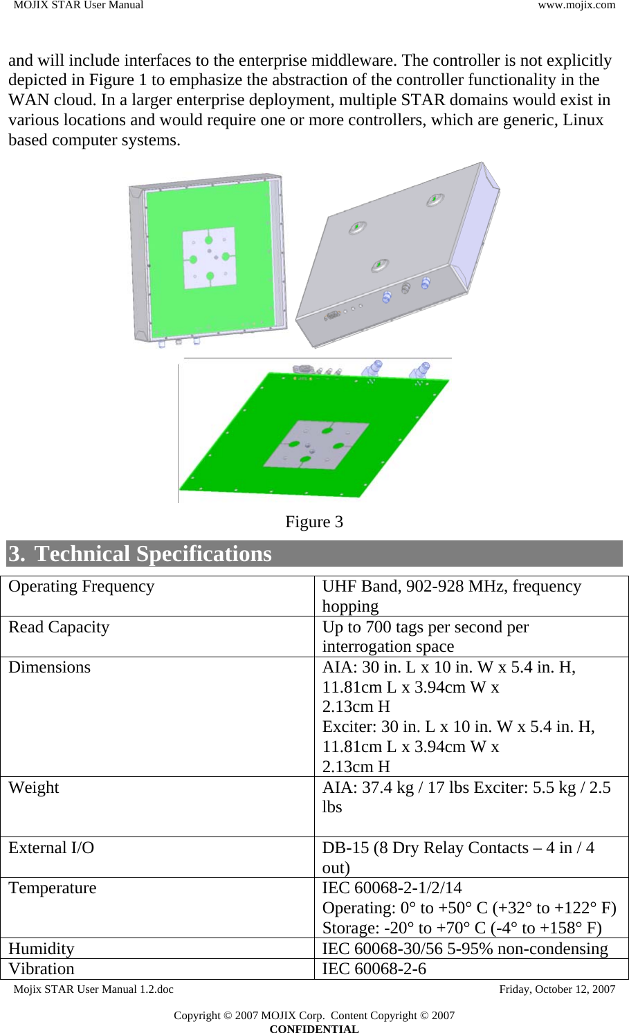
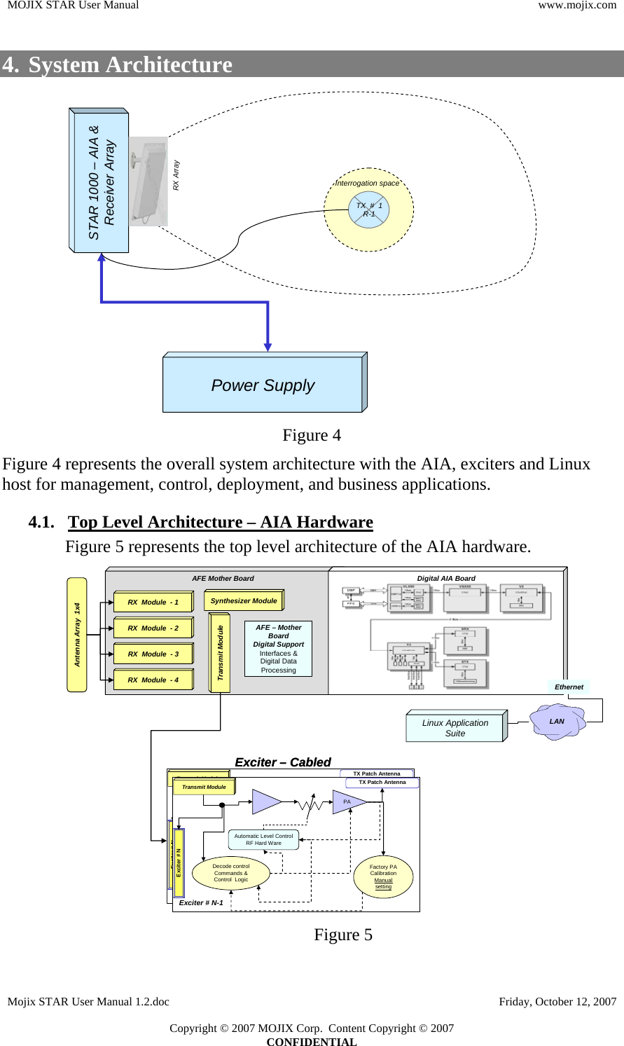
![MOJIX STAR User Manual www.mojix.com 1. Overview The origin of Mojix's technology lies in deep space communication theory. By utilizing time, frequency and space dimensions in processing the received signal from the RFID tag, Mojix technology provides more than a 30dB increase in link budget when compared to existing RFID readers. The result is far greater accuracy in read reliability and up to 10 times improvement in read/write range. With this breakthrough radio performance, the Mojix STAR-1000 can be configured to achieve any degree of location accuracy for each RFID tag located in the coverage area. In addition to the fundamental breakthrough in digital packet radio design and performance, the Mojix STAR-1000 platform has the ability to offer consistent read rates for nearly all types of goods using advanced signal processing techniques. The STAR-1000 can utilize Mojix’s Channel Codes (MCC) which is an algorithm used to ensure and recover tag integrity. MCC solves the problem of reading tags impeded in line-of-sight from the receive antenna by neighboring objects, such as reading cases in the middle of a densely packed pallet. MCC seamlessly and reliably solves the problem of pallet integrity or electronic proof-of-delivery (ePOD). This encoding scheme is ameans by which each case on a pallet is tagged and uniquely identified and in the event that some set of those tags fail or are manipulated, then MCC provides a mechanism to re-build the tag code content. Figure 1 The Mojix family of products can be configured to transmit and receive across the UHF band [902 MHz to 928 MHz] and can operate in both the near and far fields which makes it possible for a single system to read tags at the pallet, carton or item level. The UHF, or ISM band as it is commonly referred to, is partially allocated for public use and is heavily utilized by many different devices and applications which makes operating in this spectrum especially challenging. Mojix provides both ‘interference nulling’ and ‘interference excision’ Interference nulling mitigates the interference in the space dimension by minimizing the impinging energy from Mojix STAR User Manual 1.2.doc Friday, October 12, 2007 Copyright © 2007 MOJIX Corp. Content Copyright © 2007 CONFIDENTIAL](https://usermanual.wiki/MOJIX/STAR1000C/User-Guide-867719-Page-3.png)