Users Manual
MOJIX STAR User Manual www.mojix.com
MOJIX STAR
User Manual
MOJIX Corporation
Space-Time-Array Reader
• Date: 10/12/07
•
Contact: Paul Barriga
•
Organization Customer Support
•
Location: Los Angeles, CA
•
E-mail: support@mojix.com
• Telephone: 310-479-9021
Document Revision History:
Date Revision Revised By Approved By
6-11-07 Rev 1.0 Paul Barriga
9-18-07 Rev 1.1 Paul Barriga
10-12-07 Rev 1.2 Paul Barriga
Mojix STAR User Manual 1.2.doc Friday, October 12, 2007
Copyright © 2007 MOJIX Corp. Content Copyright © 2007
CONFIDENTIAL

MOJIX STAR User Manual www.mojix.com
Table of Contents
1. OVERVIEW............................................................................................................3
2. AIR INTERFACE ASSEMBLY ...........................................................................4
3. TECHNICAL SPECIFICATIONS.......................................................................5
4. SYSTEM ARCHITECTURE ................................................................................ 7
4.1. TOP LEVEL ARCHITECTURE – AIA HARDWARE.................................................7
4.2. HARDWARE ARCHITECTURE COMPONENTS .......................................................8
4.3. ALGORITHM & CONFIGURATION CONTROL ....................................................... 8
5. FCC ASSERTION..................................................................................................9
Mojix STAR User Manual 1.2.doc Friday, October 12, 2007
Copyright © 2007 MOJIX Corp. Content Copyright © 2007
CONFIDENTIAL
MOJIX STAR User Manual www.mojix.com
1. Overview
The origin of Mojix's technology lies in deep space communication theory. By utilizing
time, frequency and space dimensions in processing the received signal from the RFID
tag, Mojix technology provides more than a 30dB increase in link budget when
compared to existing RFID readers. The result is far greater accuracy in read reliability
and up to 10 times improvement in read/write range. With this breakthrough radio
performance, the Mojix STAR-1000 can be configured to achieve any degree of
location accuracy for each RFID tag located in the coverage area.
In addition to the fundamental breakthrough in digital packet radio design and
performance, the Mojix STAR-1000 platform has the ability to offer consistent read
rates for nearly all types of goods using advanced signal processing techniques. The
STAR-1000 can utilize Mojix’s Channel Codes (MCC) which is an algorithm used to
ensure and recover tag integrity. MCC solves the problem of reading tags impeded in
line-of-sight from the receive antenna by neighboring objects, such as reading cases in
the middle of a densely packed pallet. MCC seamlessly and reliably solves the problem
of pallet integrity or electronic proof-of-delivery (ePOD). This encoding scheme is
ameans by which each case on a pallet is tagged and uniquely identified and in the event
that some set of those tags fail or are manipulated, then MCC provides a mechanism to
re-build the tag code content.
Figure 1
The Mojix family of products can be configured to transmit and receive across the UHF
band [902 MHz to 928 MHz] and can operate in both the near and far fields which
makes it possible for a single system to read tags at the pallet, carton or item level. The
UHF, or ISM band as it is commonly referred to, is partially allocated for public use and
is heavily utilized by many different devices and applications which makes operating in
this spectrum especially challenging. Mojix provides both ‘interference nulling’ and
‘interference excision’ Interference nulling mitigates the interference in the space
dimension by minimizing the impinging energy from
Mojix STAR User Manual 1.2.doc Friday, October 12, 2007
Copyright © 2007 MOJIX Corp. Content Copyright © 2007
CONFIDENTIAL
MOJIX STAR User Manual www.mojix.com
the unwanted direction of arrival of the interferer. Interference excision identifies the
waveform class of the interferer and cancels the interference in frequency and time
domain in the signal processing chain of the received signal.
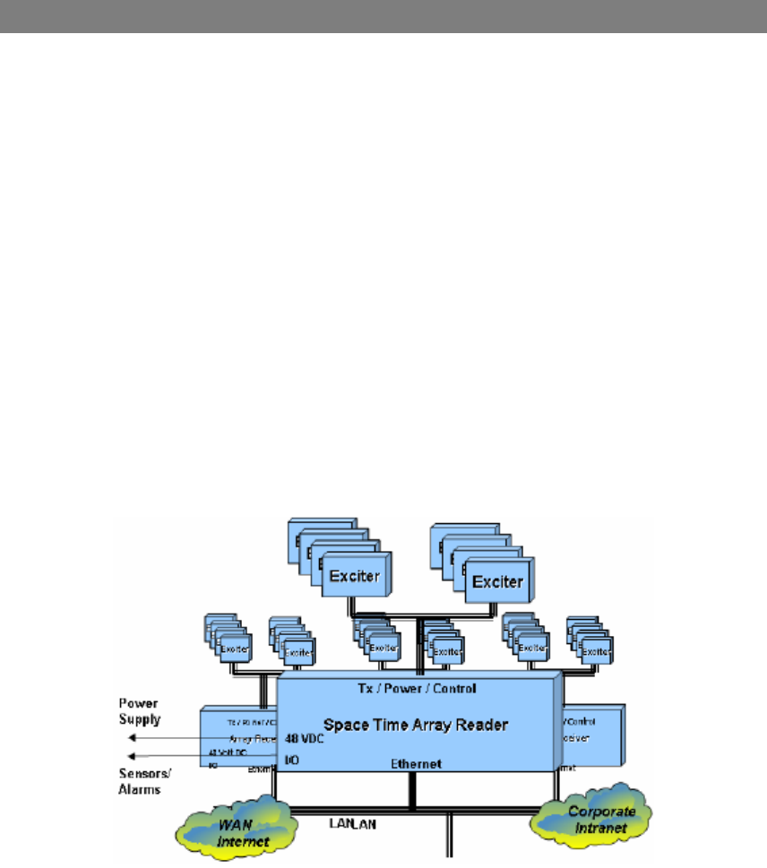
2. Air Interface Assembly
The AIA is powered directly by the 48 VDC power supply and the AIA in turn powers
each Exciter. Each exciter is connected to the AIA by RJ-50 cable, commonly used in
cable TV, and receives supply voltage, command and control signals, and baseband RF
over this medium. The AIA is typically connected to the enterprise via the LAN or an
optional WLAN.
Each exciter, as depicted in Figure 3, creates and is associated with a single
interrogation space, which is individually addressed and controlled by the AIA. Exciters
are physically positioned according to business process needs to provide optimal
performance in exciting Gen2 tags. The AIA is ordinarily positioned as an ‘eye in the
sky’ with a vantage point to all Exciters in the system – this can be line of sight (LOS)
or non-line of sight (NLOS) but always within the rated Rx range.
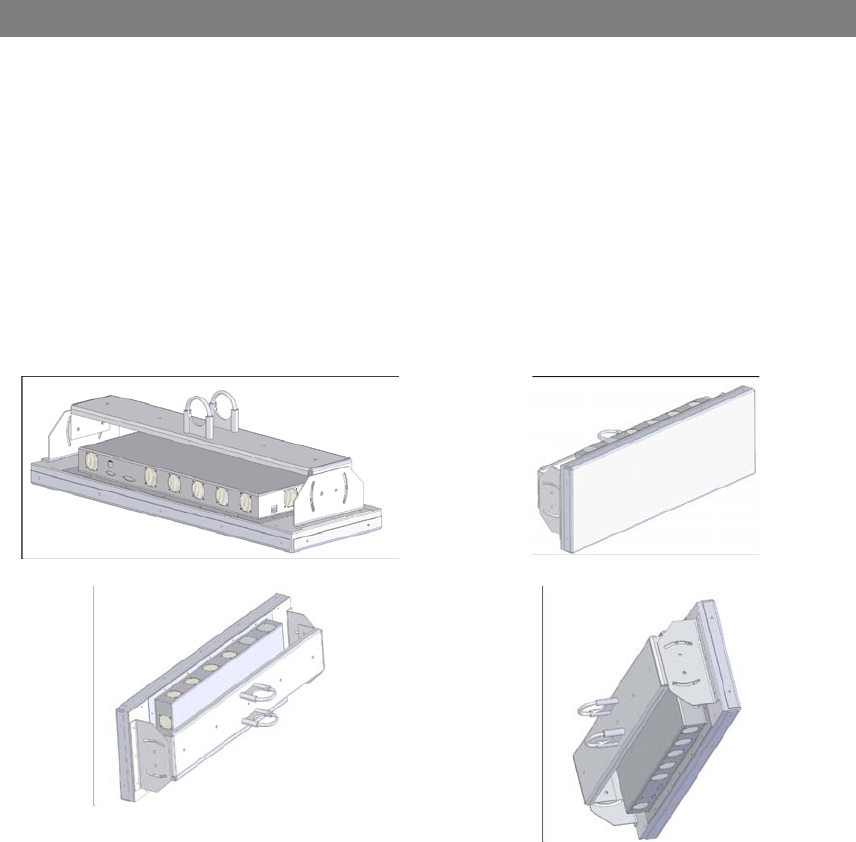
Rear View
Right View
Rear Right View
Bottom Left View
Figure 2
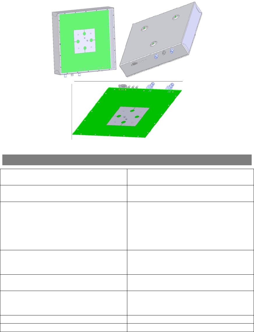
The STAR-1000 Air Interface Assembly contains a 1 x 4 array assembly, and digital
and RF processing assemblies. The overall package dimension shown in Figure 5 is 30”
x 10” x 10” (L x W x D). The AIA utilizes classical, fully active, phased array antennas
for enabling the visibility into the space dimension. The smart array approach adopted
by Mojix is based fully on digital processing techniques, thereby providing very high
resolution for estimation of direction of arrival of the signal of interest (SOI), enabling
the system to provide accurate location information on the tag position in the three
dimensional Euclidean space. The STAR-1000 AIA signal processing platform is linked
to a central, generic host computer, and controller via a standard Ethernet 10BaseT
(RJ45)-connector. The controller can drive an arbitrary number of STAR-1000 systems
Mojix STAR User Manual 1.2.doc Friday, October 12, 2007
Copyright © 2007 MOJIX Corp. Content Copyright © 2007
CONFIDENTIAL
MOJIX STAR User Manual www.mojix.com
and will include interfaces to the enterprise middleware. The controller is not explicitly
depicted in Figure 1 to emphasize the abstraction of the controller functionality in the
WAN cloud. In a larger enterprise deployment, multiple STAR domains would exist in
various locations and would require one or more controllers, which are generic, Linux
based computer systems.
Figure 3
3. Technical Specifications
Operating Frequency UHF Band, 902-928 MHz, frequency
hopping
Read Capacity Up to 700 tags per second per
interrogation space
Dimensions AIA: 30 in. L x 10 in. W x 5.4 in. H,
11.81cm L x 3.94cm W x
2.13cm H
Exciter: 30 in. L x 10 in. W x 5.4 in. H,
11.81cm L x 3.94cm W x
2.13cm H
Weight AIA: 37.4 kg / 17 lbs Exciter: 5.5 kg / 2.5
lbs
External I/O DB-15 (8 Dry Relay Contacts – 4 in / 4
out)
Temperature IEC 60068-2-1/2/14
Operating: 0° to +50° C (+32° to +122° F)
Storage: -20° to +70° C (-4° to +158° F)
Humidity IEC 60068-30/56 5-95% non-condensing
Vibration IEC 60068-2-6
Mojix STAR User Manual 1.2.doc Friday, October 12, 2007
Copyright © 2007 MOJIX Corp. Content Copyright © 2007
CONFIDENTIAL

MOJIX STAR User Manual www.mojix.com
Mojix STAR User Manual 1.2.doc Friday, October 12, 2007
ply p Power Sup +24 VDC, 2 Am
Power Consumption nal, 100 Watts in 200 Watts operatio
standby
External Antenna Connectors for Exciters (Remote RJ6 BNC
Transmitters)
Wireless LAN 1a/b/g/n integrated module Optional 802.1
WAN 3rd Party solutions available for cellular,
satellite or fiber
Indicators , Standby and Transmit LED’s for Power
Network Interface Ethernet 10/100 Base-T, RJ-45 Interface
Logical Interface • Full TCP-IP socket interface Version 4.0
ient Version 3.0
.01.01
and Version 6.0
(4thQFY07)
• SNMPv3 Cl
• FTP / Telnet Version 2.0
• HTTP Version 1.3
• IPSec Version A.02
• SSL Version 2.0
Application Programming Interface Version 1.5.0 Java VM Interface
Compliance Safety: UL60950-01
Regulatory: FCC Part 15
Firmware Upgrade pable Web-based and remote ca
RFID Reader Interface Global Low Level Reader Protocol EPC
Version 1.0
Tag Protocols EPC Gen2
Synchronization me Protocol Network Ti
IP Addressing Static and Dynamic
Host Interface Protocols XML
Warranty Year from date of shipment 1
Extended Warranty Available
Copyright © 2007 MOJIX Corp. Content Copyright © 2007
CONFIDENTIAL
MOJIX STAR User Manual www.mojix.com
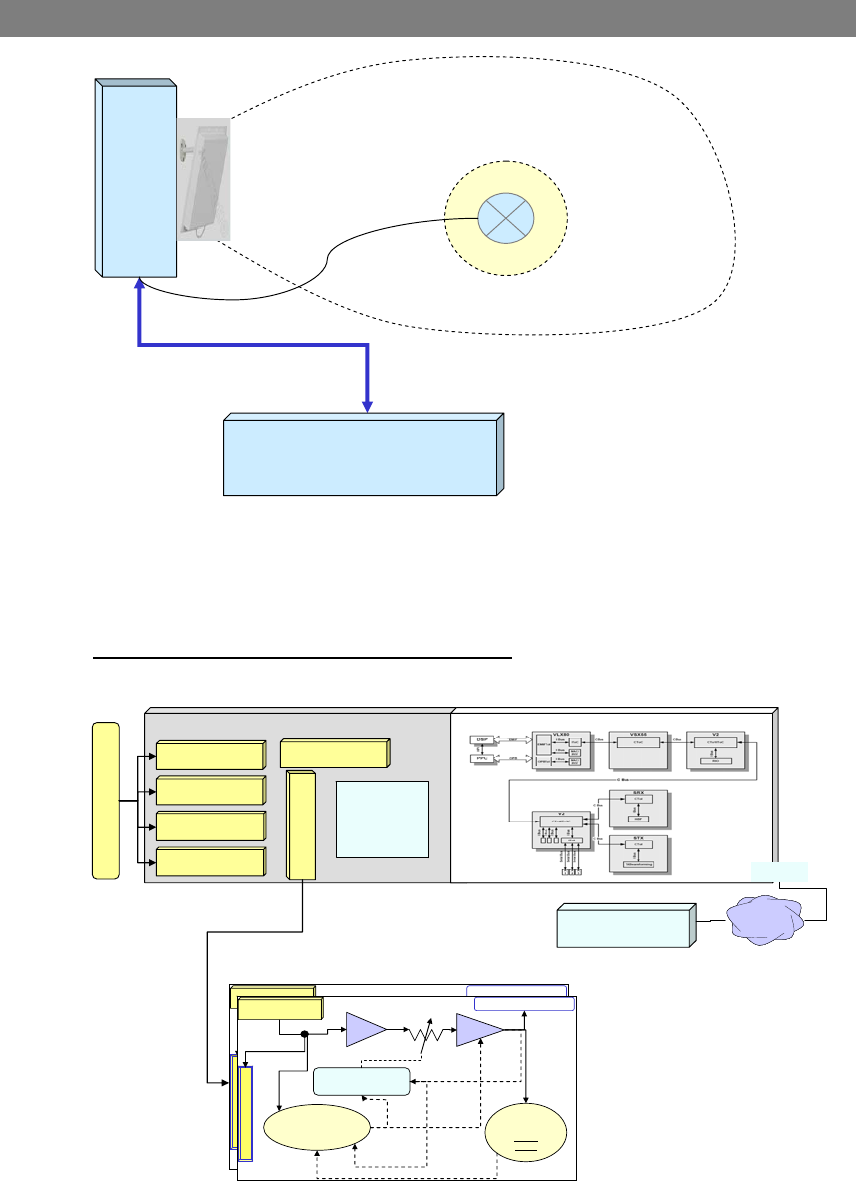
4. System Architecture
STAR 1000 – AIA &
Receiver Array
TX # 1
R-1
Interrogation space
RX Array
Power Supply
Figure 4
Figure 4 represents the overall system architecture with the AIA, exciters and Linux
host for management, control, deployment, and business applications.
4.1. Top Level Architecture – AIA Hardware
Figure 5 represents the top level architecture of the AIA hardware.
Antenna Array 1x4
AFE Mother Board
AFE – Mother
Board
Digital Support
Interfaces &
Digital Data
Processing
RX Module - 1
RX Module - 2
RX Module - 3
RX Module - 4
Synthesizer Module
Transmit Module
Digital AIA BoardDigital AIA Board
Linux Application
Suite
Ethernet
LANLAN
Exciter # N
Decode control
Commands &
Control Logic
Automatic Level Control
RF Hard Ware
PA
Factory PA
Calibration
Manual
setting
TX Patch Antenna
Transmit Module
Exciter # N
Decode control
Commands &
Control Logic
Automatic Level Control
RF Hard Ware
PA
Factory PA
Calibration
Manual
setting
TX Patch Antenna
Transmit Module
Exciter # N-1
Exciter – Cabled
Exciter # N
Decode control
Commands &
Control Logic
Automatic Level Control
RF Hard Ware
PA
Factory PA
Calibration
Manual
setting
TX Patch Antenna
Transmit Module
Exciter # N
Decode control
Commands &
Control Logic
Automatic Level Control
RF Hard Ware
PA
Factory PA
Calibration
Manual
setting
TX Patch Antenna
Transmit Module
Exciter # N-1
Exciter – Cabled
Figure 5
Mojix STAR User Manual 1.2.doc Friday, October 12, 2007
Copyright © 2007 MOJIX Corp. Content Copyright © 2007
CONFIDENTIAL
MOJIX STAR User Manual www.mojix.com
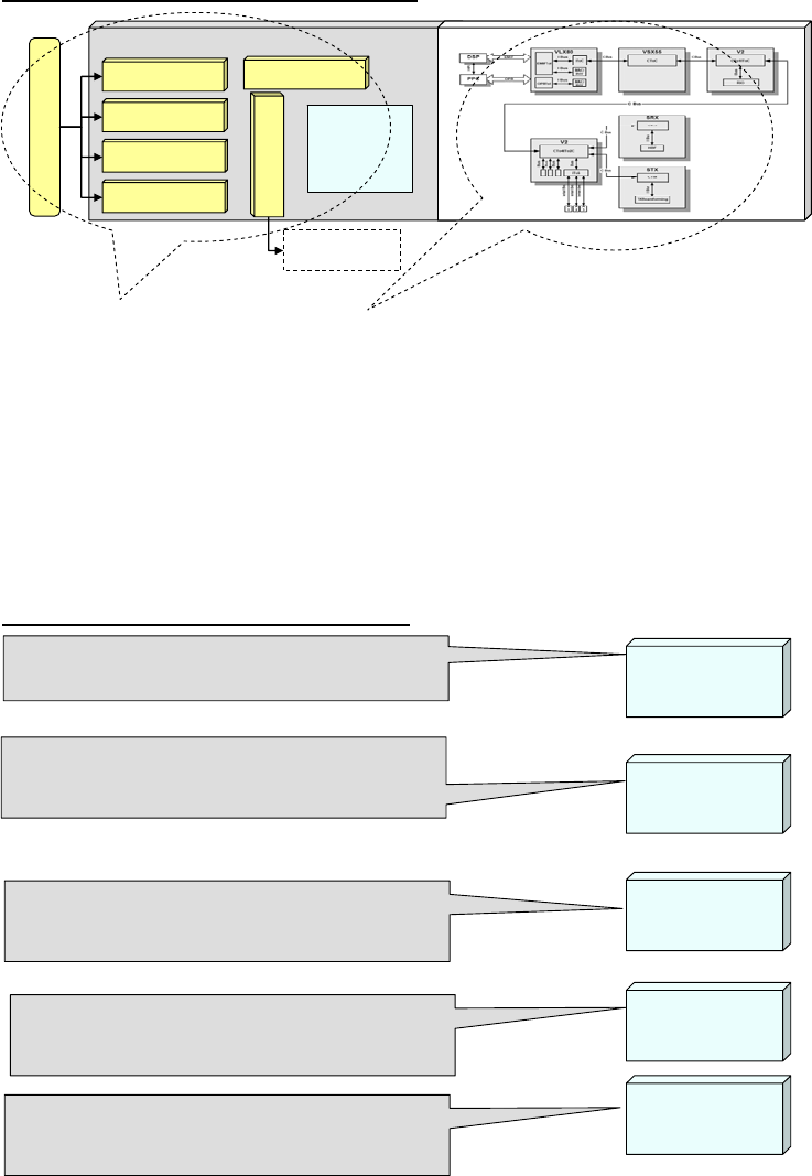
4.2. Hardware Architecture Components
Mojix STAR User Manual 1.2.doc Friday, October 12, 2007
•MAC
•Digital Filters
•Preamble detect
•Decoders
–MSNC
–SISO
•Beam Forming
•Control logic
•External Interfaces
•Excite controls & management
Antenna Array 1x4
AFE Mother Board
AFE – Mother
Board
Digital Support
Interfaces &
Digital Data
Processing
RX Module - 1
RX Module - 2
RX Module - 3
RX Module - 4
Synthesizer Module
Transmit Module
Digital AIA BoardDigital AIA Board
Exciters
Exciters
•Antenna Array
•Exciter interface
•Receive modules
•TX modules
•Synthesizer
•DACs
•ADCs
•Digital and Analog
Filer
•Control logic
Figure 6
4.3. Algorithm & Configuration Control
•Configure all EPC Gen II parameters (ie, TX &
RX rates, modulation, etc )
EPC Gen II
Config.
•Configure and setup the beam former algorithm
“This is still under calibration and development”
Beam Former
Config
•Configure and setup decoder algorithms – (select
MSNC, vs SISO)
Decoder
MSNS / SISO
Exciters
Configuration
•Configure and setup exciters
•Setup parameters include (….)
•RFID inventory and access rounds
•Tools for configuring, analyzing and processing
tag data
Applications
Figure 7
Copyright © 2007 MOJIX Corp. Content Copyright © 2007
CONFIDENTIAL

MOJIX STAR User Manual www.mojix.com
5. FCC Assertion
INSTRUCTION TO THE USER
This equipment has been tested and found to comply with the limits for a class B digital
device, pursuant to part 15 of the FCC Rules. These limits are designed to provide
reasonable protection against harmful interference in a residential installation. This
equipment generates, uses and can radiate radio frequency energy and if not installed
and used in accordance with the instructions, may cause harmful interference to radio
communications. However, there is no guarantee that interference will not occur in a
particular installation. If this equipment does cause harmful interference to radio or
television reception, which can be determined by turning the equipment off and on, the
user is encouraged to try to correct the interference by one or more of the following
measures:
• Reorient or relocate the receiving antenna.
• Increase the separation between the equipment and receiver.
• Connect the equipment into an outlet on a circuit different from that to which the
receiver is connected.
• Consult the dealer or an experienced radio/TV technician for help.
This equipment has been certified to comply with the limits for a class B computing
device, pursuant to FCC Rules. In order to maintain compliance with FCC regulations,
shielded cables must be used with this equipment. Operation with non-approved
equipment or unshielded cables is likely to result in interference to radio and TV
reception. The user is cautioned that changes and modifications made to the equipment
without the approval of manufacturer could void the user’s authority to operate this
equipment.
CAUTION: To comply with FCC RF exposure compliance requirements, a separation
distance of 20 cm must be maintained between the antenna of this device and all
persons.
Mojix STAR User Manual 1.2.doc Friday, October 12, 2007
Copyright © 2007 MOJIX Corp. Content Copyright © 2007
CONFIDENTIAL