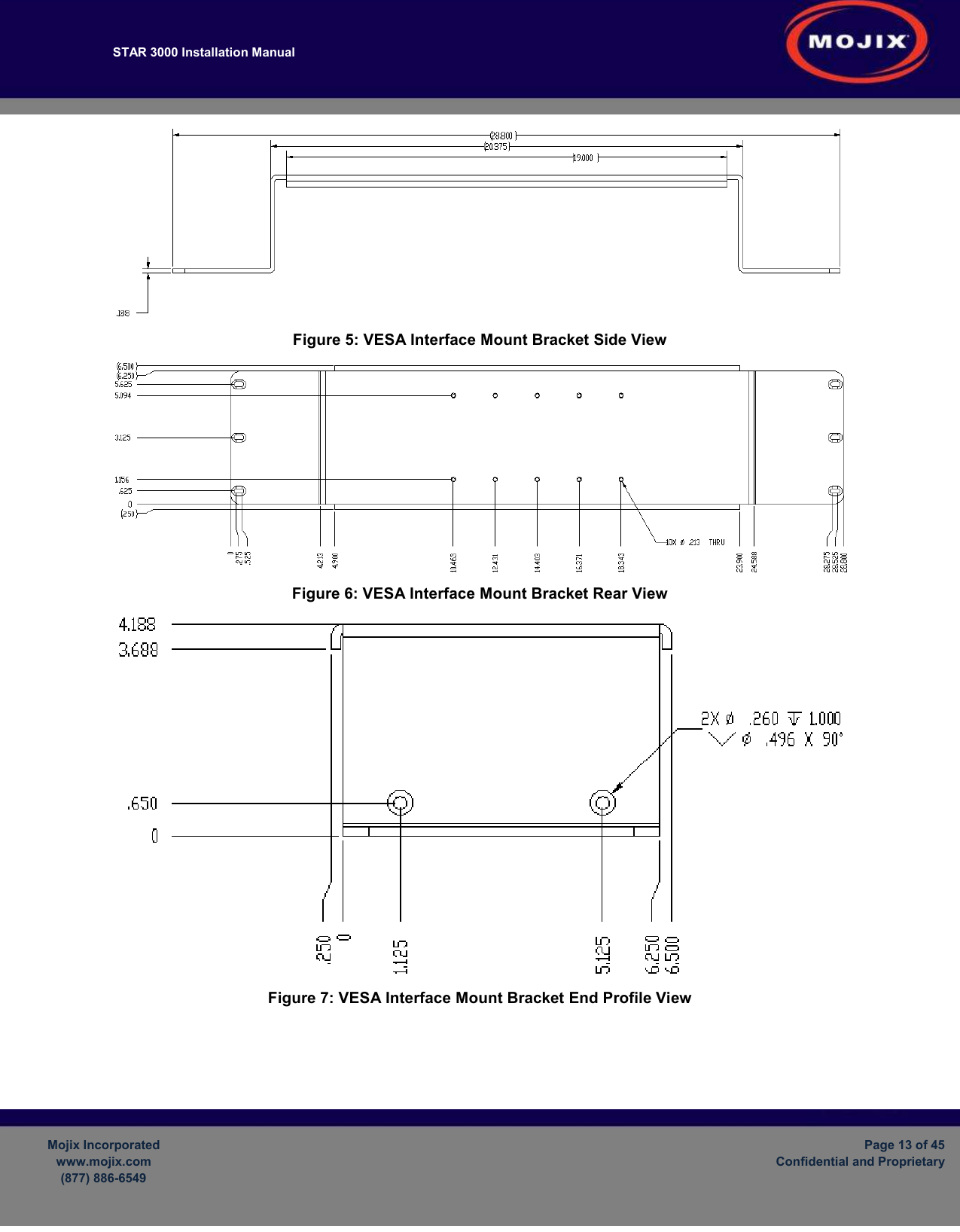
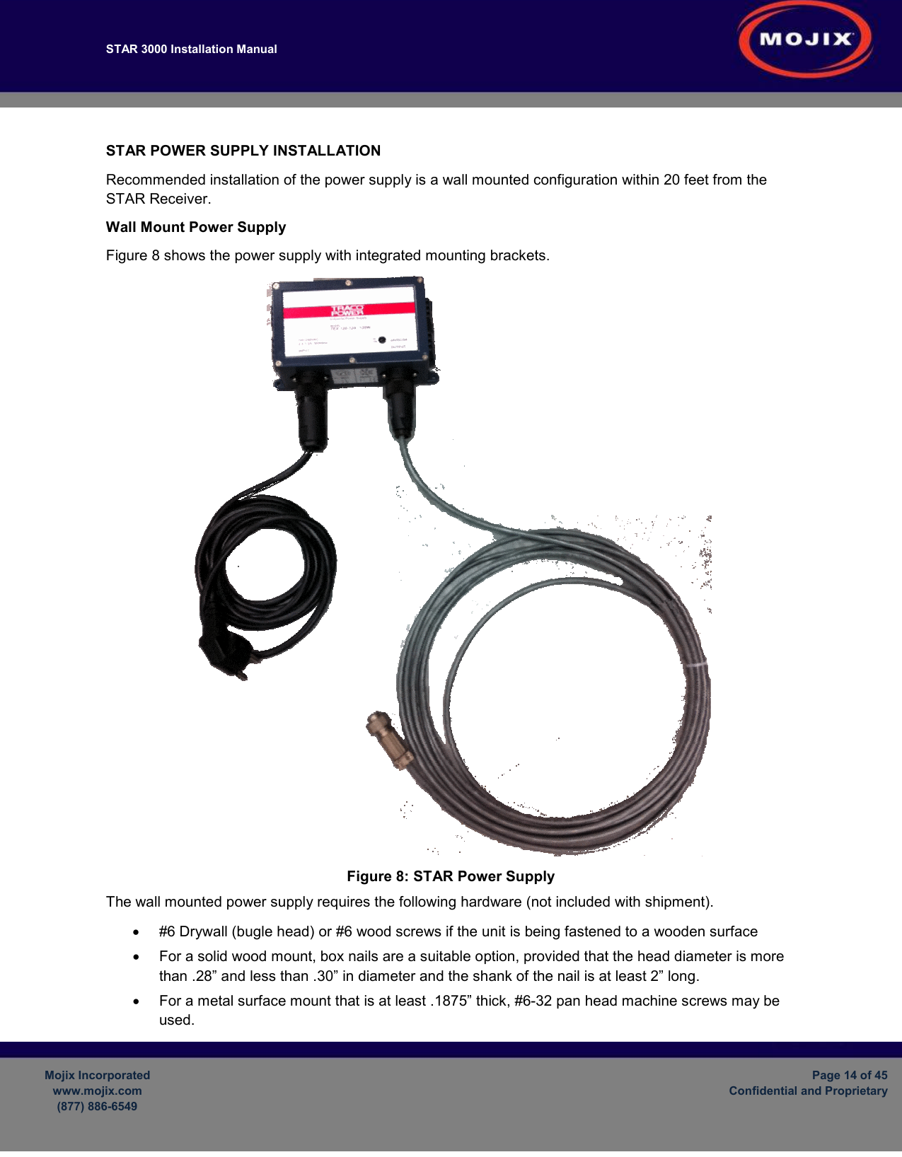
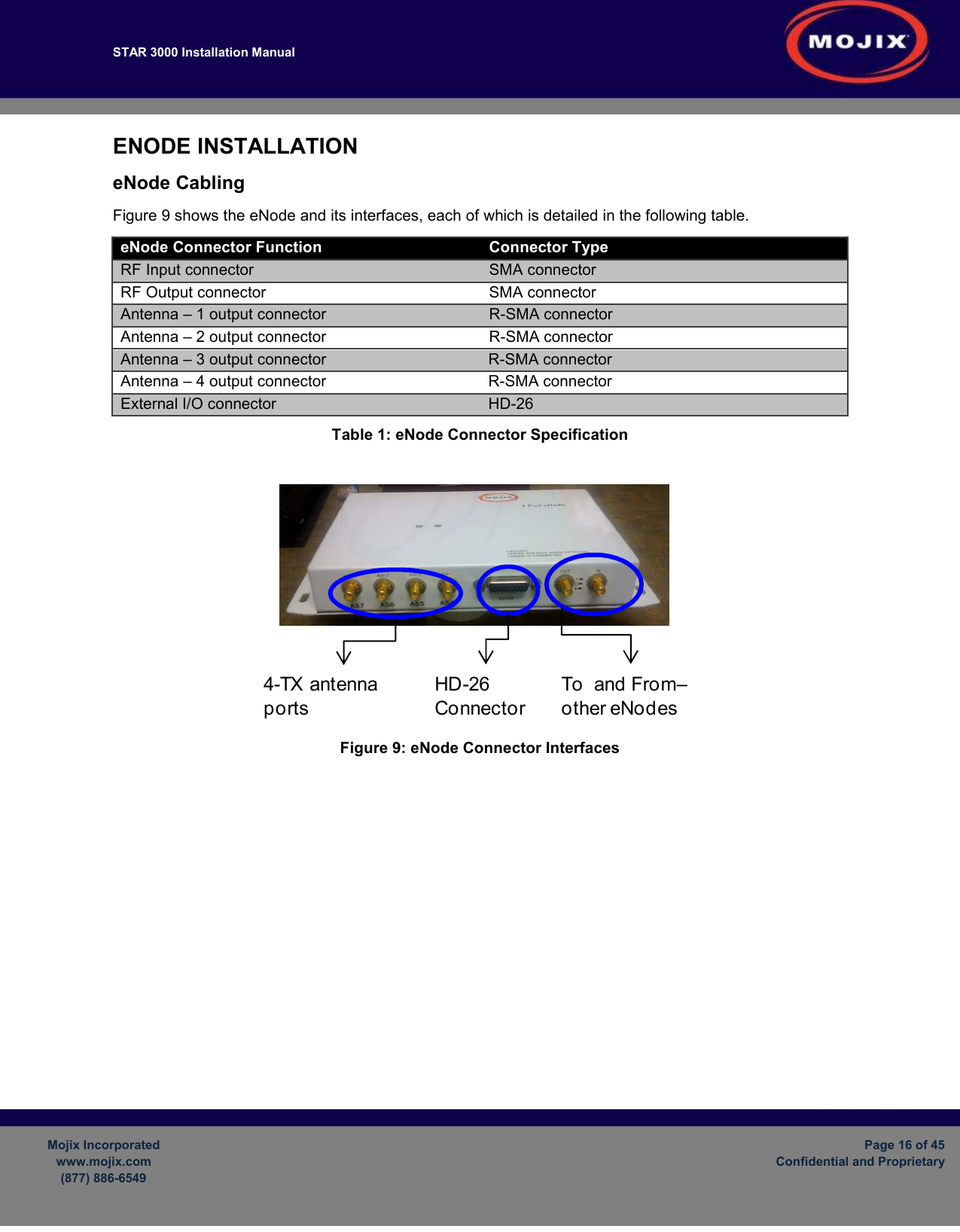
MOJIX STAR3000 Star 3000 System RFID Reader User Manual
MOJIX, Inc. Star 3000 System RFID Reader
UserManual.wiki
>
MOJIX
>
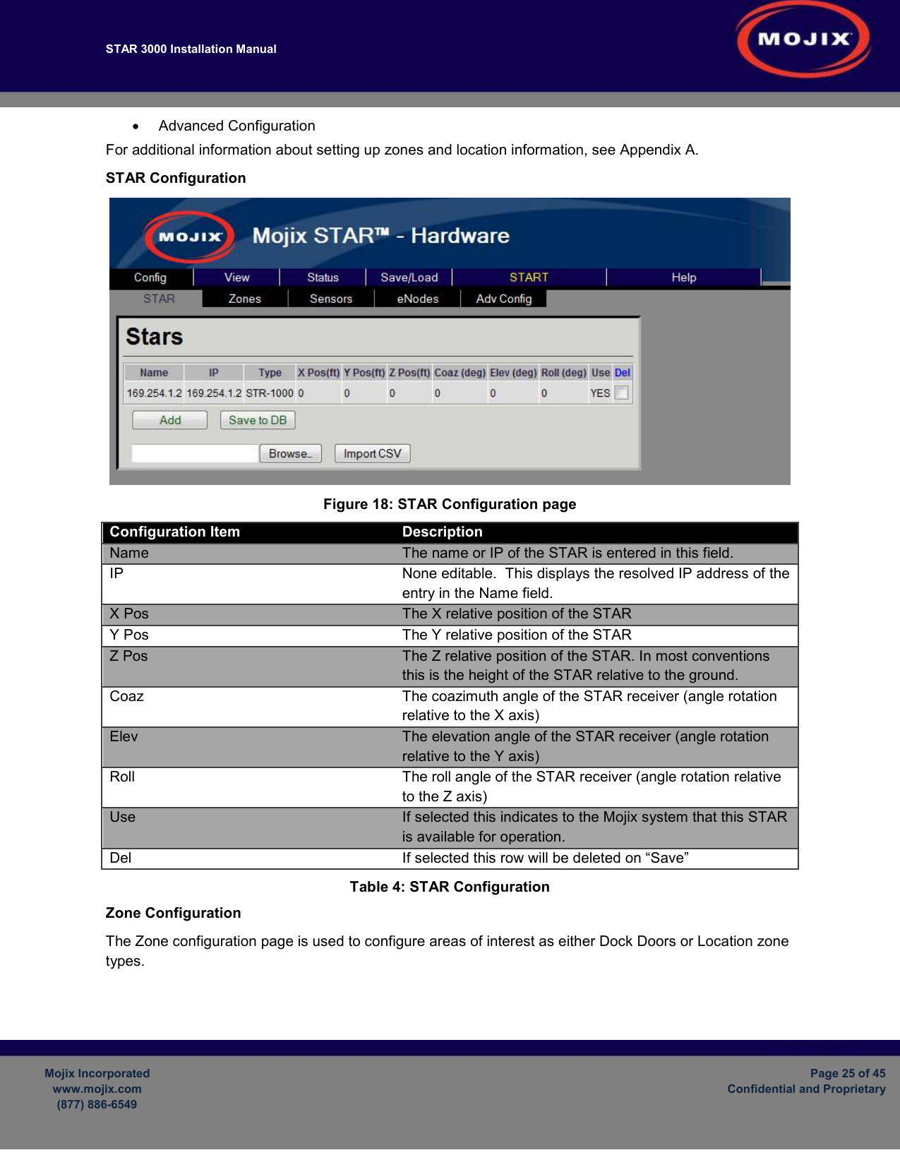
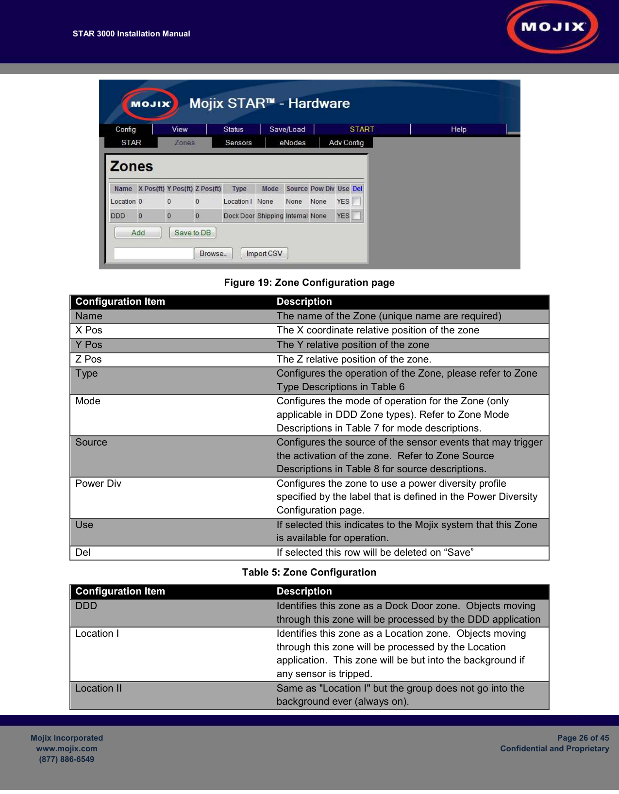
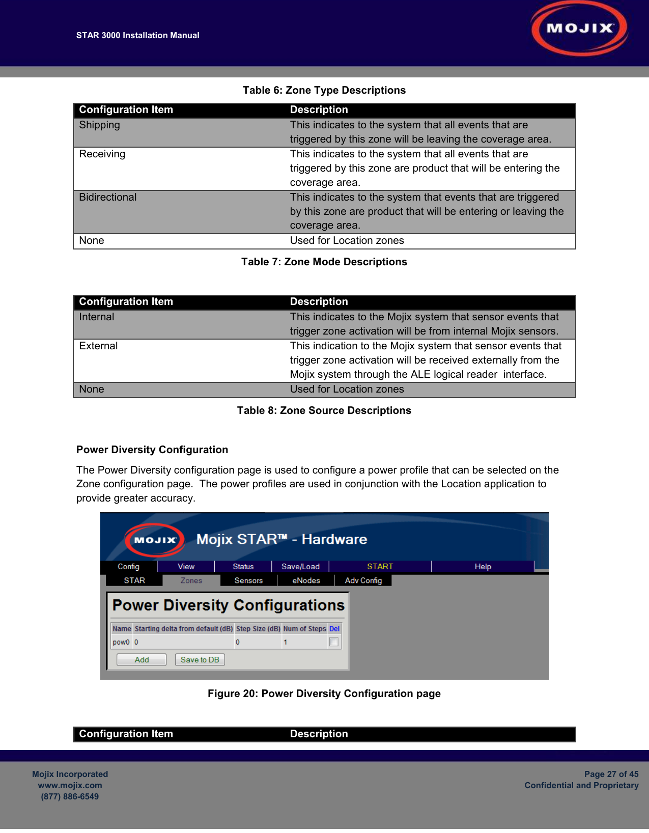
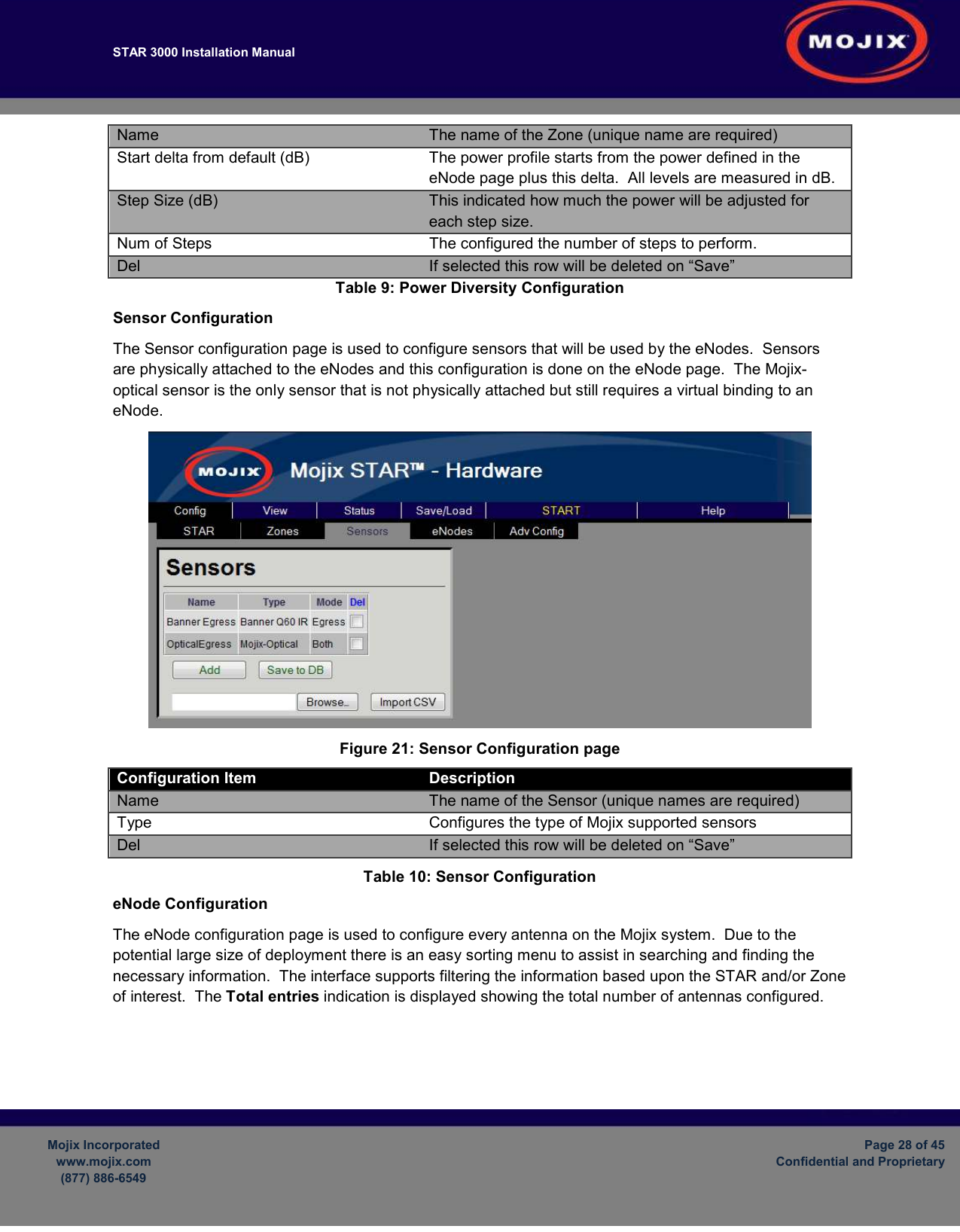
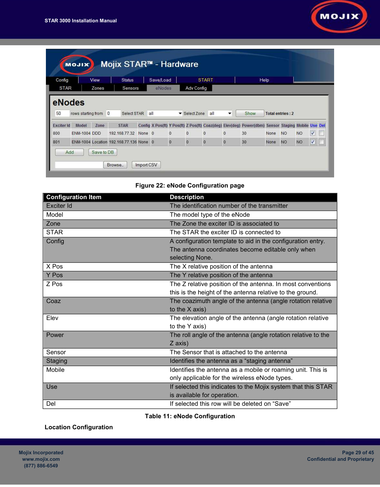
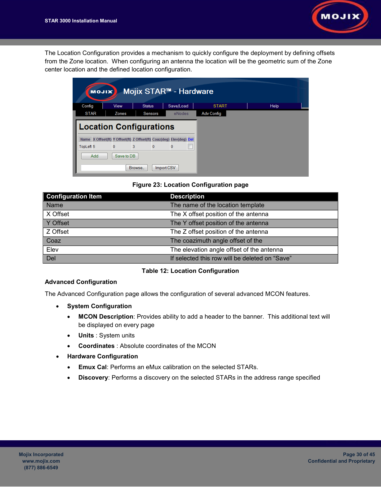
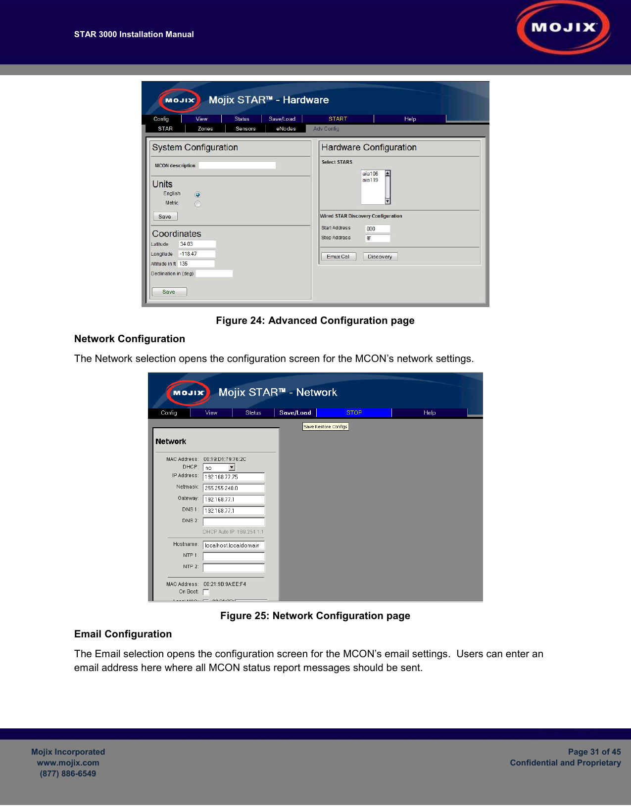
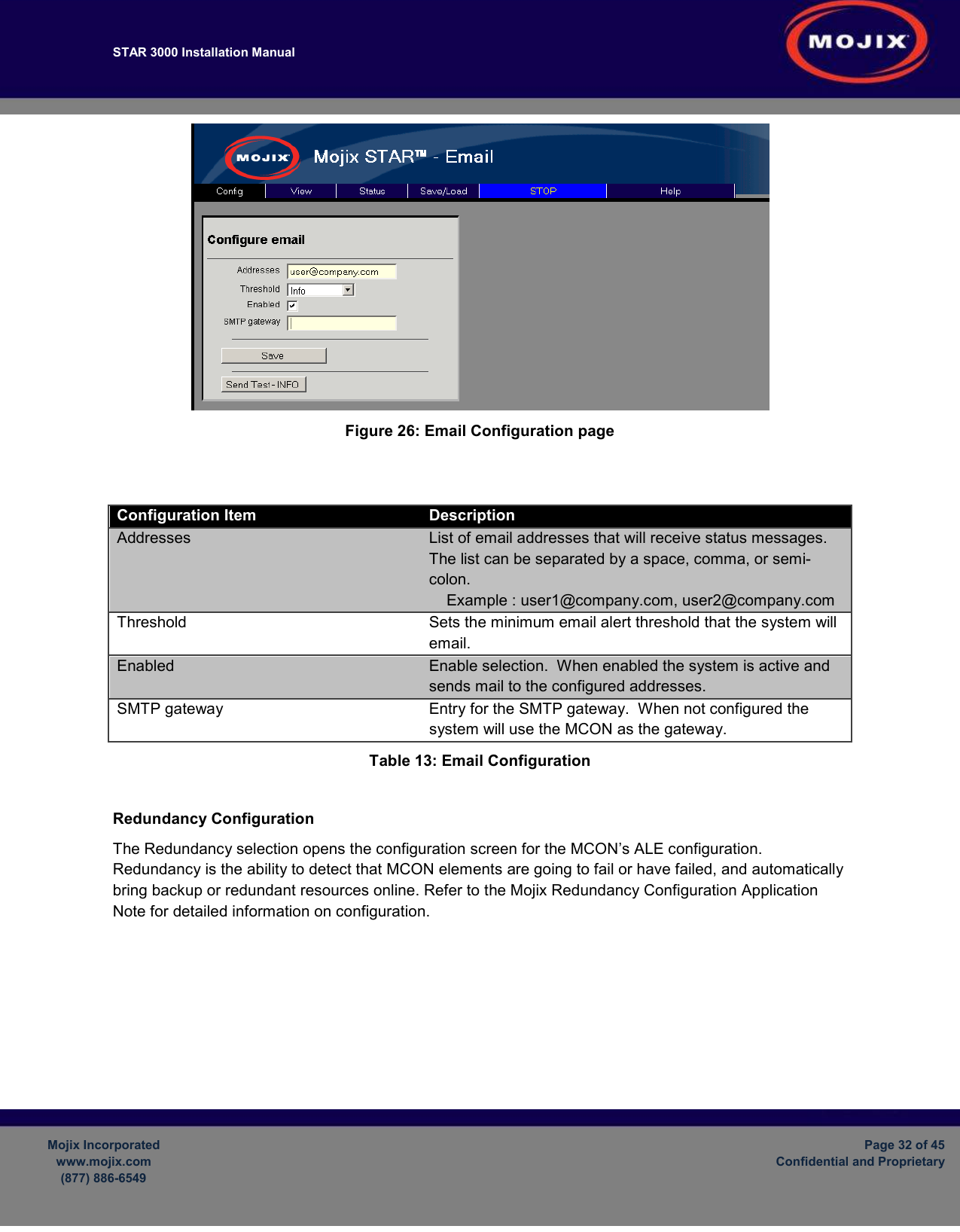
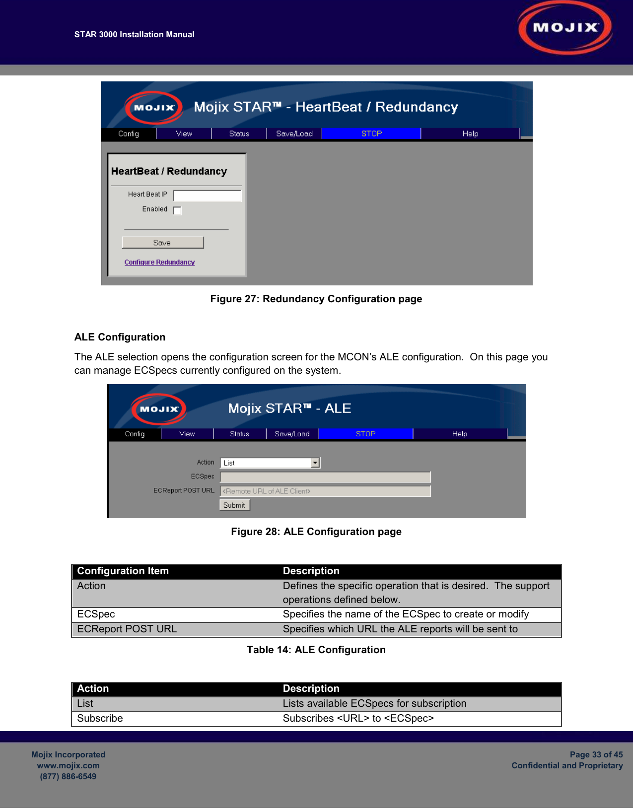
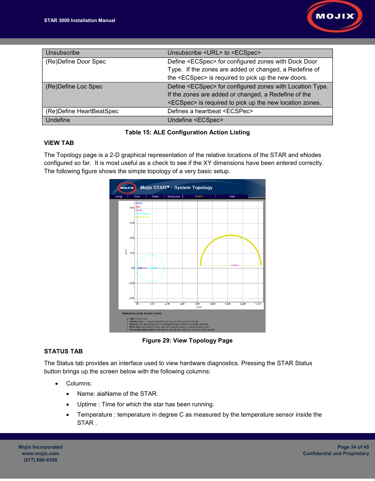
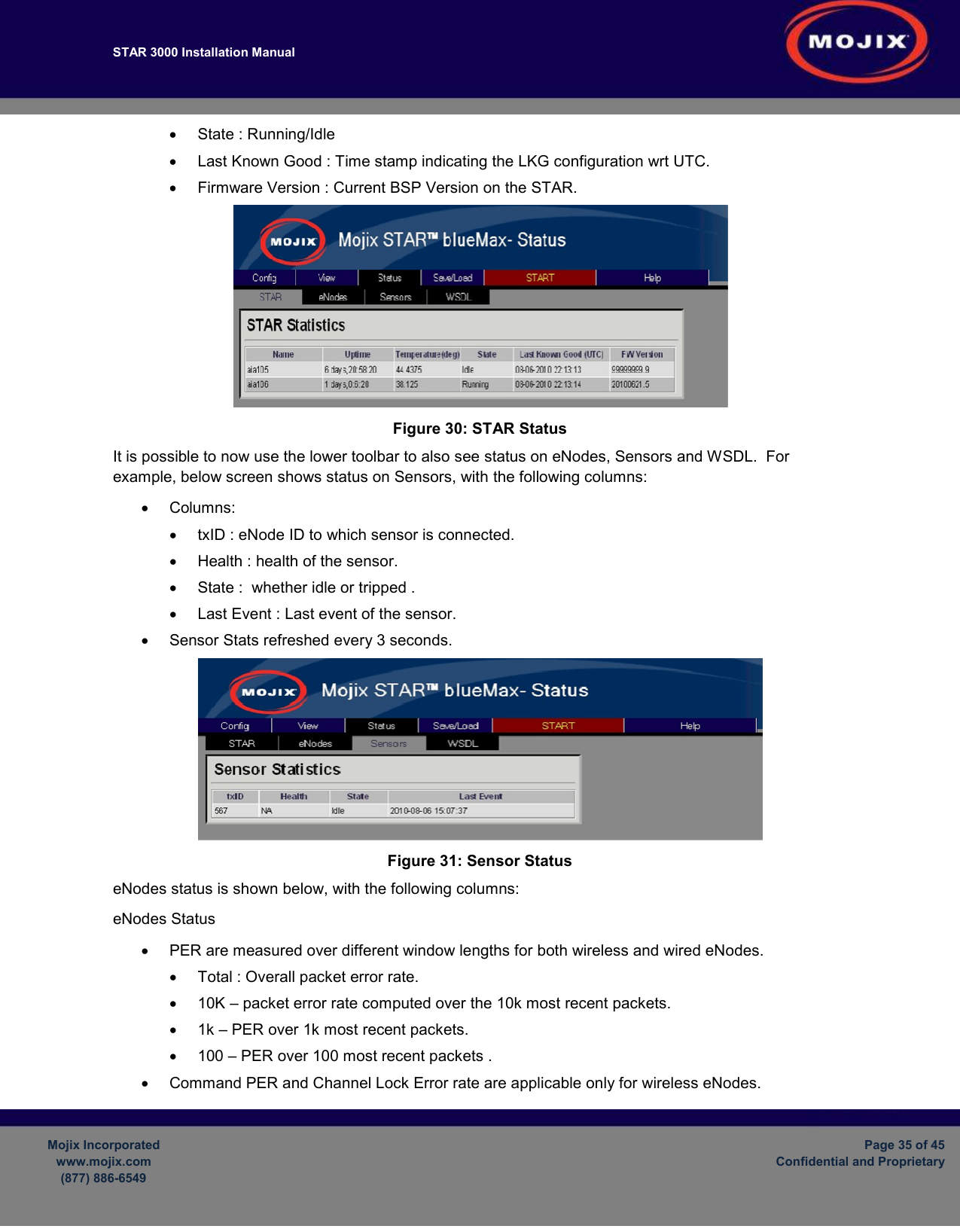
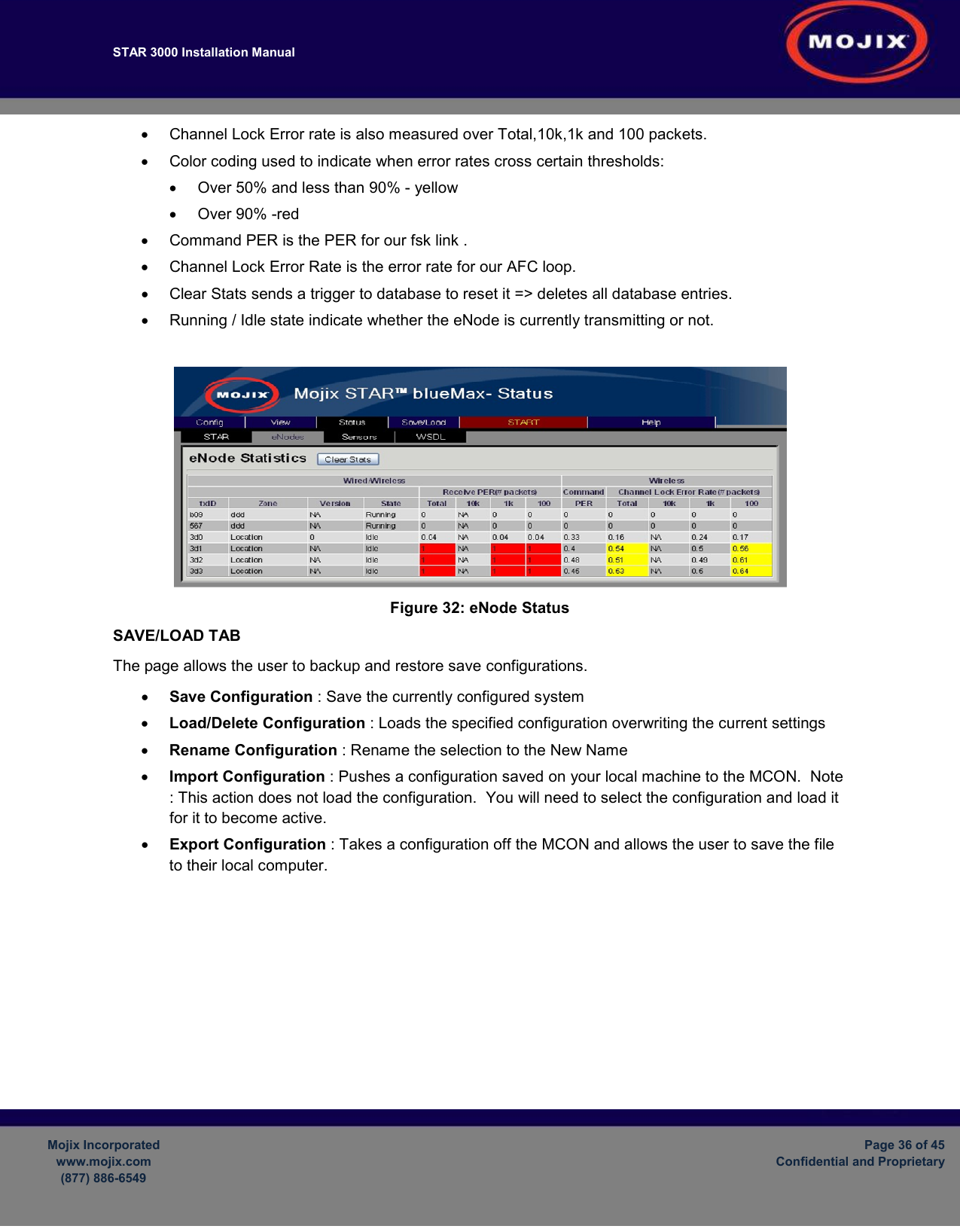
STAR3000 User Manual
User Manual
Navigation menu
Upload a User Manual
Namespaces
Wiki Guide
HTML
PDF
Info
Views
User Manual
Discussion / Help
Navigation