MOJIX STAR3000 Star 3000 System RFID Reader User Manual
MOJIX, Inc. Star 3000 System RFID Reader
MOJIX >
User Manual

STAR 3000 Installation Manual
Mojix Incorporated
www.mojix.com
(877) 886-6549
Page
1
of
45
Confidential and Proprietary
MOJIX STAR 3000 SYSTEM INSTALLATION MANUAL
RELEASE 2.2.X

STAR 3000 Installation Manual
Mojix Incorporated
www.mojix.com
(877) 886-6549
Page
2
of
45
Confidential and Proprietary
CONTENTS
Contents ........................................................................................................................................................ 2
Figures .......................................................................................................................................................... 4
Tables ............................................................................................................................................................ 5
Revision Control ............................................................................................................................................ 6
Legal Notices ................................................................................................................................................ 7
System Components ..................................................................................................................................... 8
Mojix eNodes: Distributed Transmitters .................................................................................................... 8
STAR Receiver: Centralized Read and Control point ............................................................................... 8
Master Controller ....................................................................................................................................... 8
STAR: Physical Interfaces ......................................................................................................................... 9
Cabled System Topology .......................................................................................................................... 9
System Components ................................................................................................................................... 10
Wireless STAR System Topology ........................................................................................................... 10
STAR Receiver Installation ......................................................................................................................... 12
STAR Receiver Installation...................................................................................................................... 12
STAR power supply installation .................................................................................................................. 14
eNode Installation ....................................................................................................................................... 16
eNode Cabling ......................................................................................................................................... 16
eMux Installation ......................................................................................................................................... 17
About Insertion Loss ................................................................................................................................ 17
eMux Specifications ................................................................................................................................. 18
Master Controller Installation ...................................................................................................................... 19
MCON Deployment Overview ................................................................................................................. 19
Redundancy Summary ............................................................................................................................ 19
System Network Setup ................................................................................................................................ 21
Connecting to the MCON ............................................................................................................................ 21
Changing MCON Network Settings ............................................................................................................ 21
Changing STAR Network Settings .............................................................................................................. 22
MCON Configuration ................................................................................................................................... 24
Graphical User Interface .......................................................................................................................... 24
Config Tab ................................................................................................................................................... 24
View Tab ..................................................................................................................................................... 34
Status Tab ................................................................................................................................................... 34
Save/Load Tab ............................................................................................................................................ 36
Help Tab ...................................................................................................................................................... 37
Appendix A: Engineering Interface - Mojo .................................................................................................. 39

STAR 3000 Installation Manual
Mojix Incorporated
www.mojix.com
(877) 886-6549
Page
3
of
45
Confidential and Proprietary
Appendix B: FCC Notice, STAR 3000 And eNode ..................................................................................... 43
Appendix C: FCC Notice, eMux .................................................................................................................. 44

STAR 3000 Installation Manual
Mojix Incorporated
www.mojix.com
(877) 886-6549
Page
4
of
45
Confidential and Proprietary
FIGURES
Figure 1: STAR Physical Interfaces .............................................................................................................. 9
Figure 2: STAR System Topology .............................................................................................................. 10
Figure 3: Wireless STAR System Topology ................................................................................................ 11
Figure 4: STAR 3000 VESA Interface Mount Bracket ................................................................................ 12
Figure 5: VESA Interface Mount Bracket Side View ................................................................................... 13
Figure 6: VESA Interface Mount Bracket Rear View .................................................................................. 13
Figure 7: VESA Interface Mount Bracket End Profile View ........................................................................ 13
Figure 8: STAR Power Supply .................................................................................................................... 14
Figure 9: eNode Connector Interfaces ........................................................................................................ 16
Figure 10: Example Cabling Diagram for eNodes and eMuxes.................................................................. 17
Figure 11: eMux Connector Interfaces ........................................................................................................ 18
Figure 12: Front Panel of IBM M3 X3550 ................................................................................................... 19
Figure 13: Redundant Power Supplies of IBM M3 X3550 .......................................................................... 19
Figure 14: Identification of Network Interfaces............................................................................................ 20
Figure 15: MCON Network Configuration ................................................................................................... 22
Figure 16: STAR Web UI Network Setup .................................................................................................... 23
Figure 17: Main Web Control Landing Page ............................................................................................... 24
Figure 18: STAR Configuration page .......................................................................................................... 25
Figure 19: Zone Configuration page ........................................................................................................... 26
Figure 20: Power Diversity Configuration page .......................................................................................... 27
Figure 21: Sensor Configuration page ........................................................................................................ 28
Figure 22: eNode Configuration page ......................................................................................................... 29
Figure 23: Location Configuration page ...................................................................................................... 30
Figure 24: Advanced Configuration page ................................................................................................... 31
Figure 25: Network Configuration page ...................................................................................................... 31
Figure 26: Email Configuration page .......................................................................................................... 32
Figure 27: Redundancy Configuration page ............................................................................................... 33
Figure 28: ALE Configuration page ............................................................................................................. 33
Figure 29: View Topology Page .................................................................................................................. 34
Figure 30: STAR Status .............................................................................................................................. 35
Figure 31: Sensor Status ............................................................................................................................ 35
Figure 32: eNode Status ............................................................................................................................. 36
Figure 33: Save/Load Page ........................................................................................................................ 37
Figure 34: About Page ................................................................................................................................ 37
Figure 35: STAR Upgrade Page ................................................................................................................. 38
Figure 36: Mojo Main Screen ...................................................................................................................... 39
Figure 37: eNode Configuration (eNode Tab)............................................................................................. 40
Figure 38: Tag Reads ................................................................................................................................. 40
Figure 40: Auto Inventory Controls ............................................................................................................. 41
Figure 41: Receive Parameters .................................................................................................................. 41
Figure 51: Transmit Parameters ................................................................................................................. 41
Figure 42: Select Statements ...................................................................................................................... 42
Figure 43: Access Statements .................................................................................................................... 42
Figure 44: Inventory Programs.................................................................................................................... 42

STAR 3000 Installation Manual
Mojix Incorporated
www.mojix.com
(877) 886-6549
Page
5
of
45
Confidential and Proprietary
TABLES
Table 1: eNode Connector Specification .................................................................................................... 16
Table 2: eMux Connector Specification ...................................................................................................... 18
Table 3: eMux Operating Specification ....................................................................................................... 18
Table 4: STAR Configuration ...................................................................................................................... 25
Table 5: Zone Configuration........................................................................................................................ 26
Table 6: Zone Type Descriptions ................................................................................................................ 27
Table 7: Zone Mode Descriptions ............................................................................................................... 27
Table 8: Zone Source Descriptions ............................................................................................................. 27
Table 9: Power Diversity Configuration ....................................................................................................... 28
Table 10: Sensor Configuration .................................................................................................................. 28
Table 11: eNode Configuration ................................................................................................................... 29
Table 12: Location Configuration ................................................................................................................ 30
Table 13: Email Configuration ..................................................................................................................... 32
Table 14: ALE Configuration ....................................................................................................................... 33
Table 15: ALE Configuration Action Listing ................................................................................................ 34

STAR 3000 Installation Manual
Mojix Incorporated
www.mojix.com
(877) 886-6549
Page
6
of
45
Confidential and Proprietary
REVISION CONTROL
Revision Date Author: Description
2.2.X-1.0.0 07/25/2011
Paul Barriga: Initial
2.2.X-1.0.1 08/23/2011
Paul Barriga: Added network setup
2.2.X-1.0.2 08/23/2011
Paul Barriga: Updated STAR power supply and bracket details
2.2.X-1.0.3 02/29/2012
Paul Barriga: Update FCC Statement on Page 43
2.2.X-1.0.4 03/06/2012
Paul Barriga: Added FCC Statement on Page 44
2.2.X-1.0.5 04/18/2012
Paul Barriga: Corrected zone coordinates descriptions
2.2.X-1.0.6 05/10/2012
Paul Barriga: Updated FCC Statement on Page 43

STAR 3000 Installation Manual
Mojix Incorporated
www.mojix.com
(877) 886-6549
Page
7
of
45
Confidential and Proprietary
LEGAL NOTICES
Copyright 2011 Mojix, Inc. All Rights Reserved.
All content contained within this document, including text, graphics, logos, icons, images, and other
materials, is the exclusive property of Mojix or its content suppliers and is protected by U.S. and
international copyright laws. The compilation (meaning the collection, arrangement, and assembly) of all
content within this document is the exclusive property of Mojix and is also protected by U.S. and
international copyright laws. The content within this document may be used as a resource. Any other use,
including the reproduction, modification, distribution, transmission, republication, display, or performance,
of the content on this website is strictly prohibited.
Mojix, Mojix STAR, Mojix eNode, Mojix eGroup, and the Mojix logo are trademarks or registered
trademarks of Mojix. All other trademarks mentioned in this document are the property of their respective
owners. The trademarks and logos contained in this document may not be used without the prior written
consent of Mojix or their respective owners.
Portions, features and/or functionality of Mojix's products are protected under Mojix patents, as well as
patents pending.
This User Manual is provided as a reference for persons who are properly trained and qualified to install
and/or operate Mojix’s RFID products. Whereas Mojix makes every effort to ensure the accuracy and
currency of its technical documentation, Mojix cannot be responsible for errors that occur in this User
Manual or for changes to Mojix’s products that might render information in this Manual obsolete. For
information regarding Mojix technical training, visit Mojix’s website (www.Mojix.com) or contact Mojix at
service@mojix.com.
Improper handling or use of RF equipment can result in damage to property or injury to personnel.
FCC Compliance
This equipment has been tested and found to comply with the limits for Class A digital device, pursuant to
Part 15 of the FCC Rules. Any change or modification to this product voids the user’s authority to operate
per FCC Part 15 Subpart A. Section 15.21 regulations.

STAR 3000 Installation Manual
Mojix Incorporated
www.mojix.com
(877) 886-6549
Page
8
of
45
Confidential and Proprietary
SYSTEM COMPONENTS
The Mojix STAR system is a single network element at the enterprise edge. Based on Mojix's innovative
distributed architecture, a single system consists of one or more STAR units managing up to 512 low-cost
Mojix eNode transmitters. Mojix eNodes provide energy to all passive RFID tags within their specified
interrogation spaces, while the centralized, high-sensitivity Mojix STAR reads the resulting tag signals
from across the system's potentially vast coverage area of more than 250,000 sq. feet (24,000 sq.
meters).
Mojix eNodes: Distributed Transmitters
Mojix eNodes are reliable, autonomously operated RF repeaters designed to excite all EPC UHF Gen2
RFID tags within their designated interrogation spaces. Although excite ranges are dependent on tag
sensitivity, they can range to over 100 feet. Each eNode antenna excites all passive RFID tags within its
designated interrogation space and includes form factors to accommodate both fixed and mobile
infrastructures. eNodes can be deployed as needed to shape discrete, overlapping or contiguous
interrogation spaces, including configurations to create virtual fences for securing tagged items.
STAR Receiver: Centralized Read and Control point
The STAR Receiver functions as a single point of data collection, provisioning, control, and integration
with enterprise systems. With the ability to detect extremely faint signals and the freedom from
conventional RFID’s line of sight restrictions, the STAR receiver works in concert with its satellite eNodes
to support one or many business processes across the entire coverage area. The STAR Receiver
contains a 1 x 4 array assembly, and digital and RF processing assemblies. The STAR Receiver utilizes
classical, fully active, phased array antennas for enabling the visibility into the space dimension. The
smart array approach adopted by Mojix is based fully on digital processing techniques, thereby providing
very high resolution for estimation of direction of arrival of the signal of interest (SOI), enabling the system
to provide accurate location information on the tag position.
Master Controller
The STAR signal processing platform is linked to an edge appliance called a Master Controller (MCON),
and communicates via a standard wired Ethernet interface. The MCON can drive an arbitrary number of
STAR systems and includes interfaces to the enterprise middleware. In a larger enterprise deployment,
multiple STAR domains exist in various locations and can require one or more Master Controllers in a
clustered configuration.
STAR 3000 Installation Manual
Mojix Incorporated
www.mojix.com
(877) 886-6549
Page
9
of
45
Confidential and Proprietary
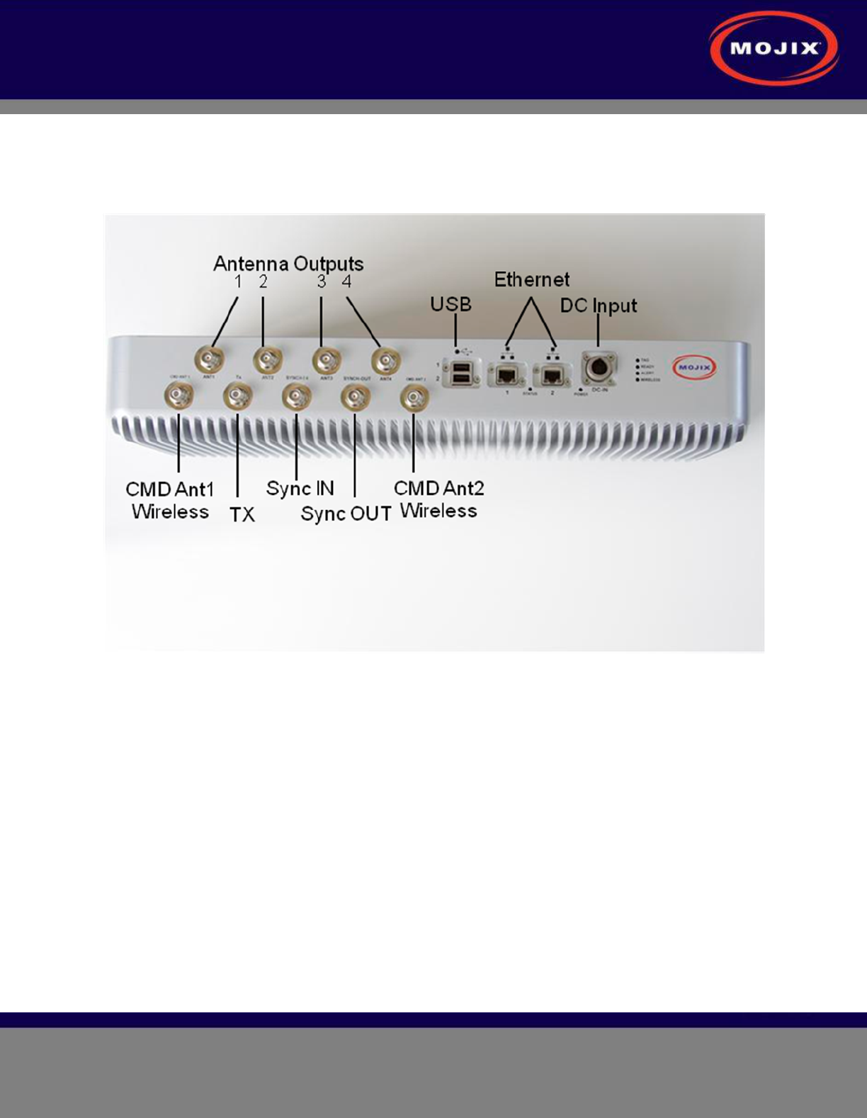
STAR: Physical Interfaces
The following picture illustrates the STAR’s physical interfaces.
Figure 1: STAR Physical Interfaces
1. 1 TX Output TNC: Transmit RF Signal, 24 Volts DC, Forward Command Signal
2. 2 TX Output TNC for Wireless eNode Network: Up to two wireless forward command antenna(s)
3. 4 RX Input TNC from Antenna(s): Inputs from receive antenna array OR individual receive antenna(s)
4. 1 RX Input TNC Sync: Input synchronization signal from master STAR (for multiple simultaneous
receiving)
5. 1 TX Output TNC Sync: Output synchronization signal to another STAR
6. 2 Ethernet Interfaces: Control from MCON, Status Monitoring and Tag Read Packets
7. 2 USB Interfaces (future use)
8. 1 DC Power Connector
Cabled System Topology
STAR 3000 Installation Manual
Mojix Incorporated
www.mojix.com
(877) 886-6549
Page
10
of
45
Confidential and Proprietary
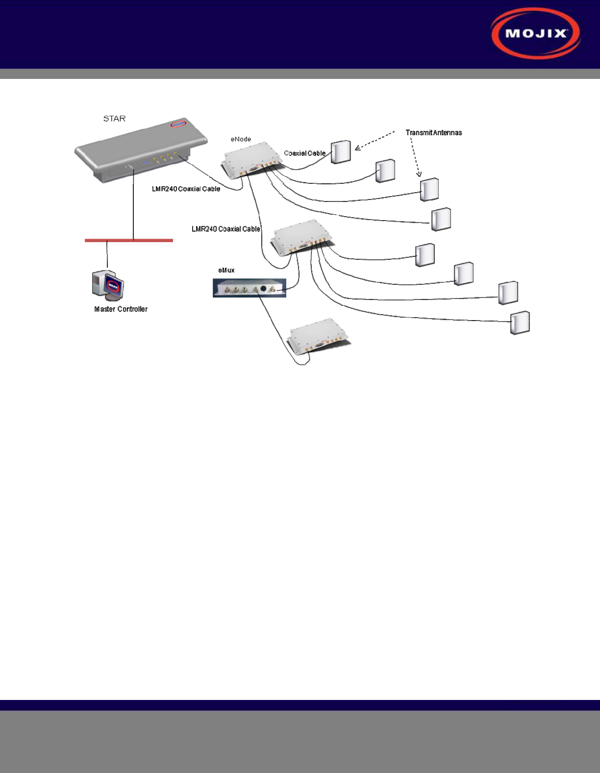
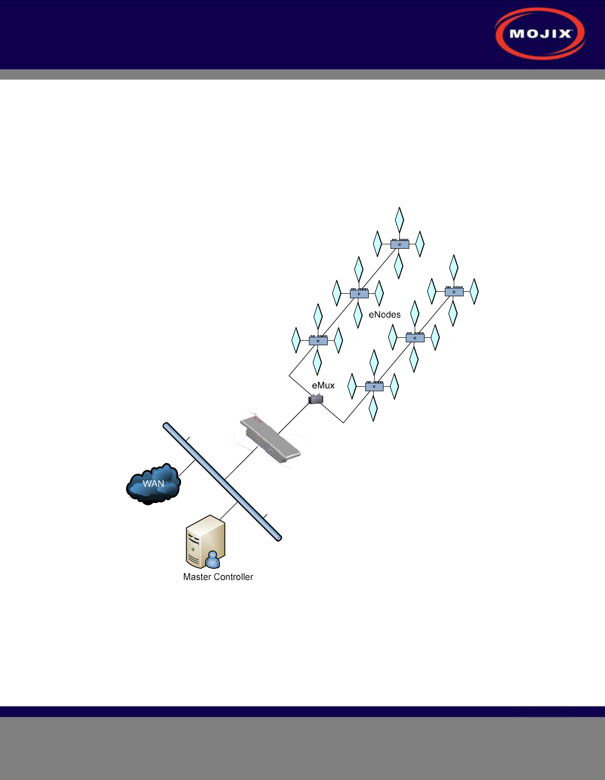
Error! Reference source not found. illustrates the components of the STAR system topology. These
items are as follows:
Figure 2: STAR System Topology
SYSTEM COMPONENTS
1. STAR
2. eMux: splitter and amplifier for the RF signal
3. eNode: controls up to 4 antennas to excite tags
4. Master Controller (MCON): application appliance
5. Optional Sensor network to detect activity in specific areas
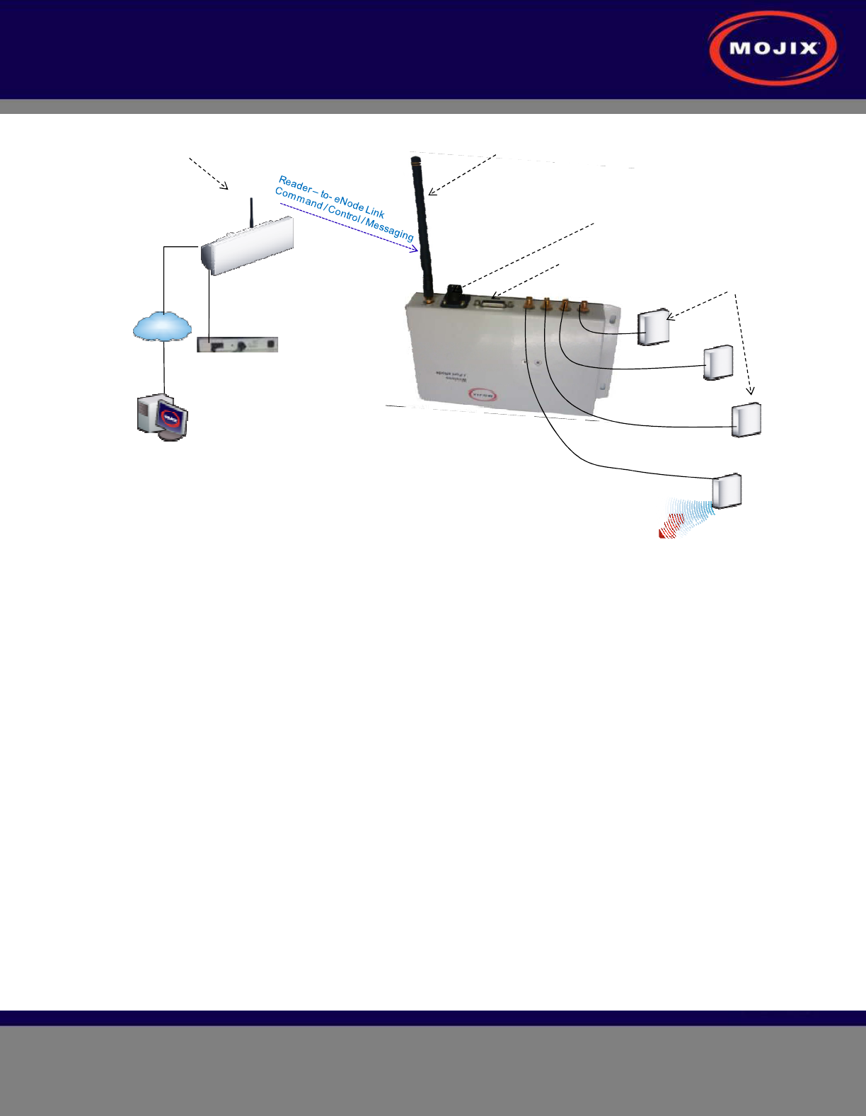
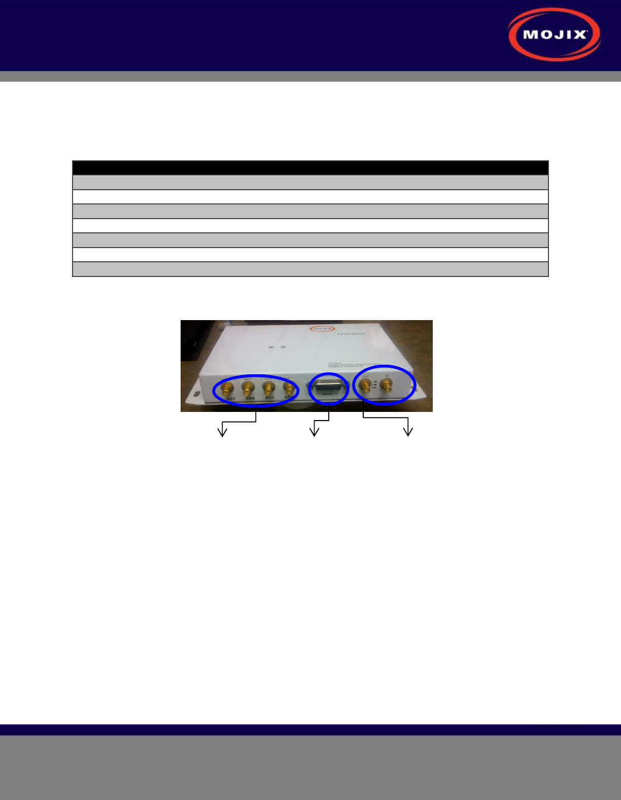
Wireless STAR System Topology
Figure 3 illustrates Wireless STAR system topology, showing:
1. STAR and power supply, including the command link antenna
2. Wireless 4-port eNode, including the command link antenna
3. Sensor port
4. eNode transmit antennas
5. MCON
STAR 3000 Installation Manual
Mojix Incorporated
www.mojix.com
(877) 886-6549
Page
11
of
45
Confidential and Proprietary
LAN line
Master Controller
Wireless
TAR Reader
LAN
Power Supply
Transmit Antenna
Wireless
4 Port eNode Coaxial Cable
Sensors
External Power Supply
Command Link
Receive Only Antenna
Command Link
Transmit Only Antenna
Tag
Figure 3: Wireless STAR System Topology
STAR 3000 Installation Manual
Mojix Incorporated
www.mojix.com
(877) 886-6549
Page
12
of
45
Confidential and Proprietary
STAR RECEIVER INSTALLATION
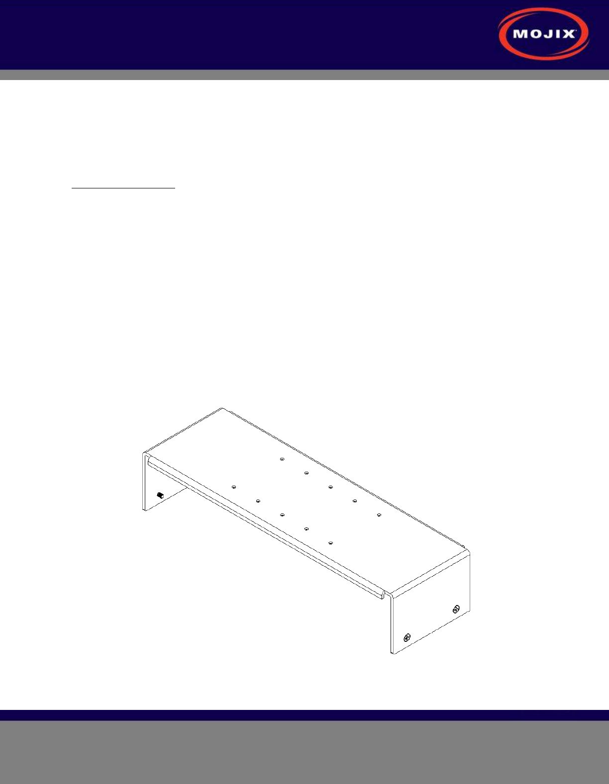
STAR Receiver Installation
The STAR is mechanically designed for post or wall mounting. Figure 4 illustrates the rear mounting
bracket. This bracket is designed to be used with any standard VESA mounting bracket. As shown in the
figure, the mounting bracket is installed directly on the STAR Receiver back plate.
Installation instructions:
1. Product installation shall be conducted by a qualified installer. The appropriate local engineer or
architect shall be consulted to ensure the wall and/or pole mount is capable of safely supporting up to
4 times the weight of the product.
2. Should the customer elect to mount the STAR to a flat surface (e.g. wall), holes are provided in the
main mounting bracket to accommodate a family of hardware (customer supplied).
3. When mounting STAR unit to a flat surface, a minimum of 4 fasteners are required, though the exact
type is a function of the wall material and construction. Best industry practice is recommended.
a. For example: toggle bolts or Molly bolts would be the first choice on hollow walls. Lead lag
shields would be recommended on solid (cast) concrete or brick. Nails are not
recommended, but could be used only if the wood material of the wall was at least 1.5" thick.
4. The STAR Receiver is first secured to the main bracket using the provided hardware. A standard
VESA bracket designed to hold 4 times the weight of the STAR unit should separately be mounted to
either a mast or a flat surface. The last step is to attach the STAR bracket to the VESA bracket.
Figure 4: STAR 3000 VESA Interface Mount Bracket

STAR 3000 Installation Manual
Mojix Incorporated
www.mojix.com
(877) 886-6549
Page
13
of
45
Confidential and Proprietary
Figure 5: VESA Interface Mount Bracket Side View
Figure 6: VESA Interface Mount Bracket Rear View
Figure 7: VESA Interface Mount Bracket End Profile View
STAR 3000 Installation Manual
Mojix Incorporated
www.mojix.com
(877) 886-6549
Page
14
of
45
Confidential and Proprietary
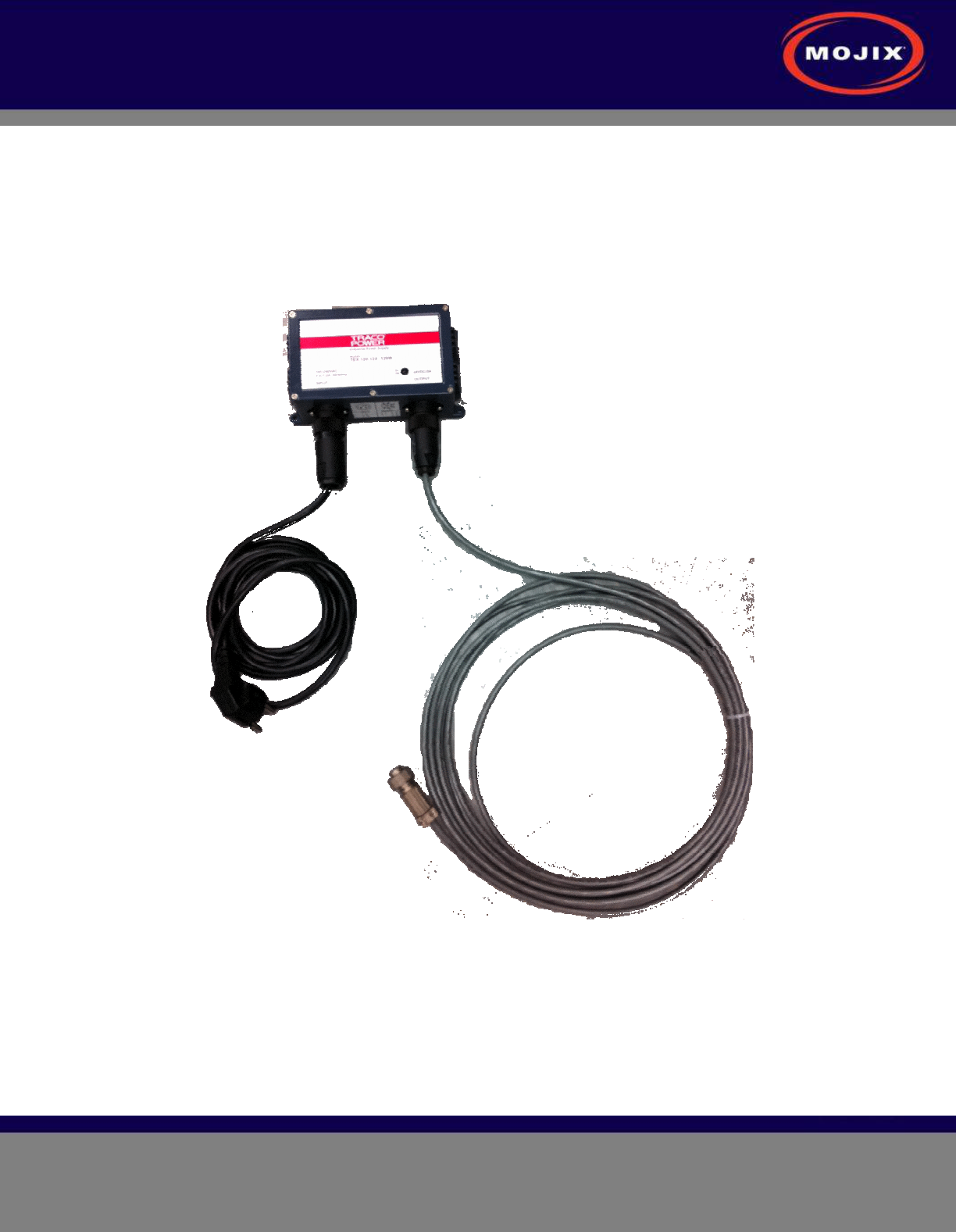
STAR POWER SUPPLY INSTALLATION
Recommended installation of the power supply is a wall mounted configuration within 20 feet from the
STAR Receiver.
Wall Mount Power Supply
Figure 8 shows the power supply with integrated mounting brackets.
Figure 8: STAR Power Supply
The wall mounted power supply requires the following hardware (not included with shipment).
• #6 Drywall (bugle head) or #6 wood screws if the unit is being fastened to a wooden surface
• For a solid wood mount, box nails are a suitable option, provided that the head diameter is more
than .28” and less than .30” in diameter and the shank of the nail is at least 2” long.
• For a metal surface mount that is at least .1875” thick, #6-32 pan head machine screws may be
used.

STAR 3000 Installation Manual
Mojix Incorporated
www.mojix.com
(877) 886-6549
Page
15
of
45
Confidential and Proprietary
• For drywall/plaster fastening, 1/8 Molly or Toggle bolts must be used.
The recommended mounting procedure is:
1. For drywall mounts, "Molly Bolts" are preferred. Alternatively, toggle bolts are a suitable option, as
they offer a pull-down force more than 4X the industry standard, and are highly recommended in
areas prone to seismic activity.
2. Alternatively for drywall mounts, Bugle-head #6 Drywall screws (coarse thread) are also acceptable, if
all 4 tie-down points are used, offering an industry standard of a pull-down strength of at least 4X the
weight of the unit.
3. If the wall thickness is at least 1/2" wood (plywood, for example), nails can also be used.
Cables must be properly dressed and supported. Both AC and DC cables should be routed with a service
loop and must be supported at least once within 18” of the power supply unit. Cables can be run in
conduit, providing (a) the conduit is not hanging on the cables, (b) the service loop exists, and (c) there is
at least one support/tie-down on the cables between conduit and power supply.
STAR 3000 Installation Manual
Mojix Incorporated
www.mojix.com
(877) 886-6549
Page
16
of
45
Confidential and Proprietary
ENODE INSTALLATION
eNode Cabling
Figure 9 shows the eNode and its interfaces, each of which is detailed in the following table.
eNode Connector Function Connector Type
RF Input connector SMA connector
RF Output connector SMA connector
Antenna – 1 output connector R-SMA connector
Antenna – 2 output connector R-SMA connector
Antenna – 3 output connector R-SMA connector
Antenna – 4 output connector R-SMA connector
External I/O connector HD-26
Table 1: eNode Connector Specification
4-TX antenna
ports
To and From–
other eNodes
HD-26
Connector
Figure 9: eNode Connector Interfaces
STAR 3000 Installation Manual
Mojix Incorporated
www.mojix.com
(877) 886-6549
Page
17
of
45
Confidential and Proprietary
EMUX INSTALLATION
eNodes frequently are deployed with eMuxes that can connect multiple eNodes to a STAR or to another
(upstream) eMux. The eMux amplifies and conditions RF signals from the STAR and provides DC power
to eNodes. This section describes the steps involved to install an eMux. eMuxes should be used either
when:
1. The insertion loss from long lengths of coaxial cables and eNodes is too high
2. The wired eNode system layout requires splitting the wiring to multiple wiring branches
Figure 10: Example Cabling Diagram for eNodes and eMuxes
About Insertion Loss
The STAR transmits a signal of +23 dBm. Insertion loss of terminated LMR240 coaxial cable at 915 MHz
is 7.5 dBm per 100 ft. Insertion loss of wired eNodes is 0.5 dBm. Input power level for an eMux must be
greater than -10 dBm. The input power level for an eNode must be greater than -5 dBm. In order to
increase the signal strength for longer cable runs or many eNodes strung together, an eMux must be
STAR 3000 Installation Manual
Mojix Incorporated
www.mojix.com
(877) 886-6549
Page
18
of
45
Confidential and Proprietary
used to amplify the signal. The maximum output level on an eMux for any of the 4 output ports is +20
dBm. The maximum gain of the eMux is 17 dB.
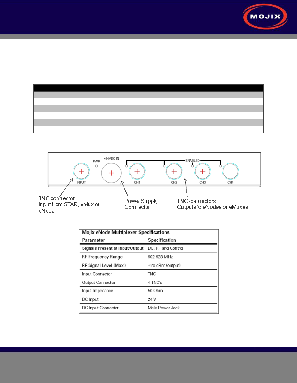
Figure 11 depicts the eMux and its interfaces, showing the RF connections as well as the power supply
connection. The connector specification is summarized in Table 2 below.
eMux Specifications
eMux Connector Function Connector Type
RF input connector TNC connector
RF output connector – 1 TNC connector
RF output connector – 2 TNC connector
RF output connector – 3 TNC connector
RF output connector – 4 TNC connector
Power Supply Connector External Power Supply
Table 2: eMux Connector Specification
Figure 11: eMux Connector Interfaces
Table 3: eMux Operating Specification
STAR 3000 Installation Manual
Mojix Incorporated
www.mojix.com
(877) 886-6549
Page
19
of
45
Confidential and Proprietary
MASTER CONTROLLER INSTALLATION
The Master Controller (MCON) is a Linux based appliance supplied by Mojix. The hardware is based on
the following specifications:
• Memory : 16 GB
• Hard Drives : 6 73 GB Drives in a RAID5 Configuration
• Power Supplies: 2 independent, hot-swappable, minimum 675 Watt AC supplies
• Processors: Two 2.8 GHz Intel Xeon Quad-Core
MCON Deployment Overview
The MCON connects to one or more STARs on a network through its network interface. The MCON
commands the STAR(s), collects tag read data, produces RTLS and door transition detection data,
monitors the health of the STAR network, and reports data to middleware applications.
MCON hardware must be installed in a temperature and environmentally controlled room.
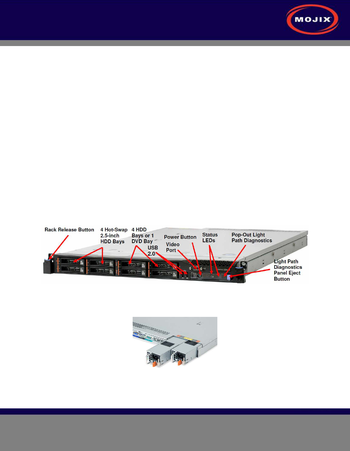
Redundancy Summary
The Mojix solution includes a robust redundancy capability within the hardware components of the Master
Controller (MCON), as well as for automatic failover redundancy of an entire MCON system to another.
Internally, the MCON features 6 hot-swap hard drives running in a RAID5 configuration. With this
configuration, a single drive can fail without disrupting any MCON functions. Replacement drives need
only be inserted in place of the failed drive and the system will automatically configure the new drive.
Figure 12: Front Panel of IBM M3 X3550
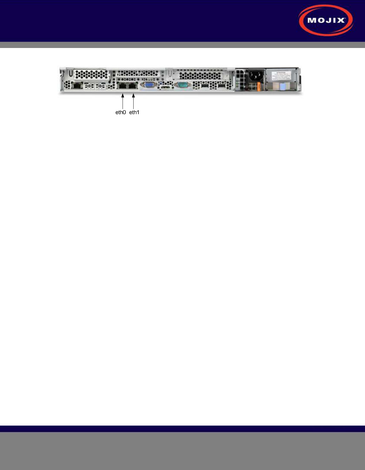
The system also features hot-swap power supplies. It is recommended that each supply use a separate
AC circuit to protect against a possible circuit failure.
Figure 13: Redundant Power Supplies of IBM M3 X3550
Once the MCON hardware is mounted and secured and prior to issuing power to the unit, connect a
network cable to the eth0 port as identified in Figure 14. The next step is to power on the unit.
STAR 3000 Installation Manual
Mojix Incorporated
www.mojix.com
(877) 886-6549
Page
20
of
45
Confidential and Proprietary
Figure 14: Identification of Network Interfaces

STAR 3000 Installation Manual
Mojix Incorporated
www.mojix.com
(877) 886-6549
Page
21
of
45
Confidential and Proprietary
SYSTEM NETWORK SETUP
The MCON has the flexibility to configure and manage the STAR unit through a Web enabled interface
called the Web Console.
CONNECTING TO THE MCON
The MCON by default uses DHCP for IP assignment. If a DHCP server is not found within 5 minutes from
power up, the MCON uses the following default IP address.
• Default Static IP: 169.254.1.1
• Default Netmask: 255.255.0.0
• Default Gateway: 169.254.1.1
It is recommended to connect the MCON using loopback/crossover cable directly to a windows PC for the
initial setup. This will ensure that the MCON defaults to the IP address above after 5 minutes. If the
MCON is instead connected to a LAN with DHCP server, it may acquire a different IP address, making it
difficult to locate on the network for first time setup.
CHANGING MCON NETWORK SETTINGS
The simplest way to change network settings of the MCON is to navigate a web browser to the MCON’s
IP address. Use the following credentials to authenticate the connection.
User: edison
Password: p4ssw0rd
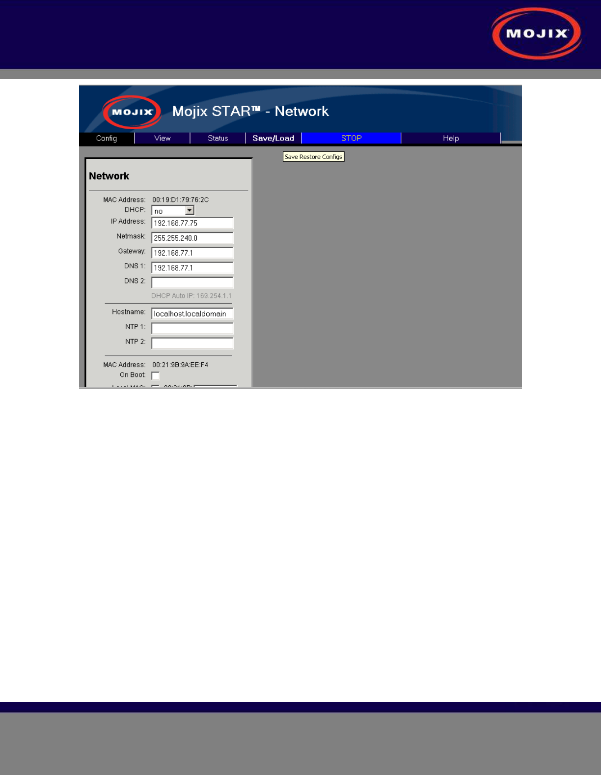
Once connected, use the Config menu to select Network. The Figure 15 shows the network configuration
screen. The user can choose between dhcp or a static IP address. Once changes are made, click on the
Save button. Changes occur within 30 seconds.
STAR 3000 Installation Manual
Mojix Incorporated
www.mojix.com
(877) 886-6549
Page
22
of
45
Confidential and Proprietary
Figure 15: MCON Network Configuration
CHANGING STAR NETWORK SETTINGS
The STAR 3000 uses DHCP for IP addressing by default. If a DHCP server is not detected within 1
minute from power up, then there are 4 temporary IP addresses assigned and remain active for 10
minutes. These addresses are as follows:
• Default Ethernet 1 Address: 169.254.1.10
• Default Ethernet 1 Netmask: 255.255.0.0)
• Default Ethernet 1 Secondary Address: 10.254.1.10
• Default Ethernet 1 Secondary Netmask: 255.0.0.0
• Default Ethernet 2 Address: 169.254.1.11
• Default Ethernet 2 Netmask: 255.255.0.0
• Default Ethernet 2 Secondary Address: 10.254.1.11
• Default Ethernet 2 Secondary Netmask: 255.0.0.0
Network settings are stored in the following file on the system: /mnt/boot/etc/rc.conf
In order to edit this file, follow this procedure:
1. Power on the STAR 3000 with an Ethernet cable connected to Ethernet 1.
STAR 3000 Installation Manual
Mojix Incorporated
www.mojix.com
(877) 886-6549
Page
23
of
45
Confidential and Proprietary
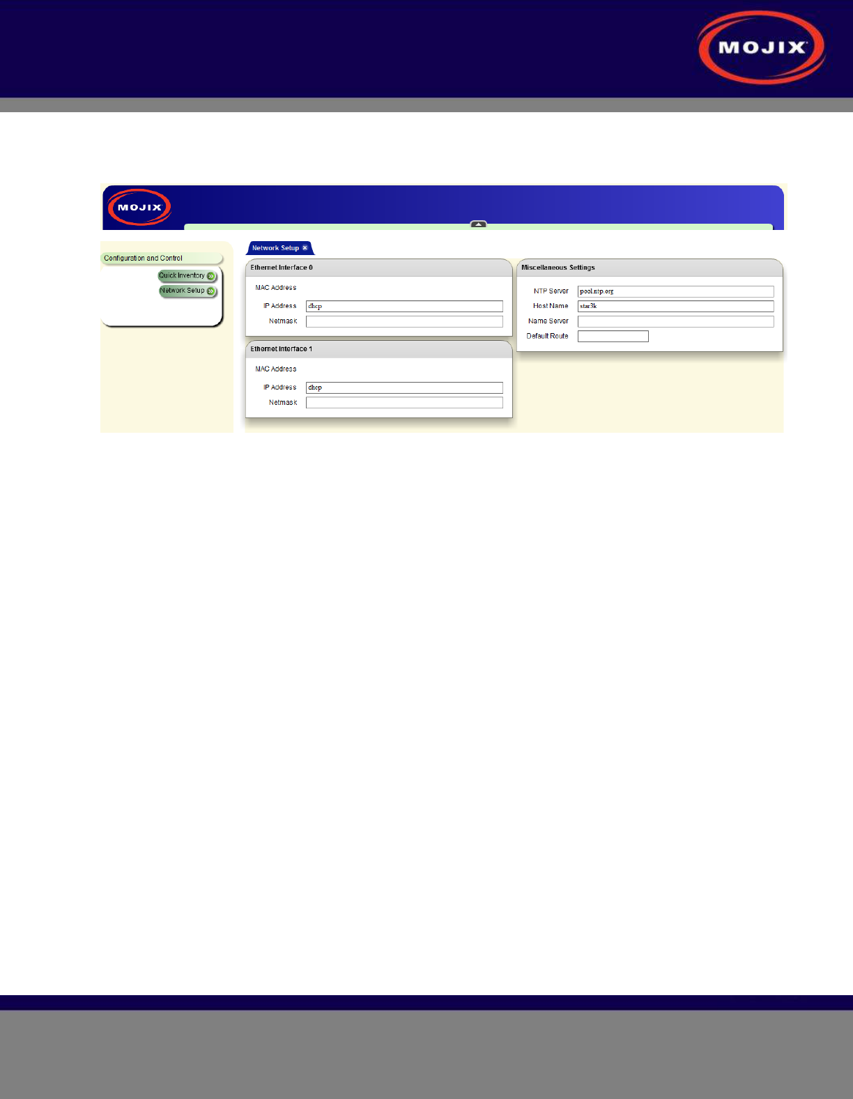
2. Method 1: Connect to the STAR by entering the default IP address listed above for Ethernet 1. Figure
16 shows the graphical interace presented to the user for network setup. Enter the desired network
addresses and then click on the Commit Changes button.
Figure 16: STAR Web UI Network Setup
3. Method 2: Log into the STAR using SSH using the following credentials:
• Username: root
• Password: root
• To edit the configuration file, the user must use the vi editor with the following command:
• vi /mnt/boot/etc/rc.conf (Note: this is an advanced method of modifying IP addresses and
assumes the user is familiar with the basics of the vi editor.)
• The file consists of lines of the format 'export VARNAME="string"
• The variables relevant to network settings for the Ethernet ports are as follows:
• Ethernet 1 Address: IPADDR0
• Ethernet 1 Netmask: NETMASK0
• Ethernet 1 Gateway: GATEWAY0
• Ethernet 2 Address: IPADDR1
• Ethernet 2 Netmask: NETMASK1
• Ethernet 2 Gateway: GATEWAY1
• To set the IP address to DHCP, enter “dhcp” instead of a qualified IP address. If DHCP is used,
then there is no need to assign a netmask or gateway.
• To use static IP addresses, the user must enter a netmask and gateway.
• Reboot the system for the changes to take place
• At the SSH command line, enter the this command: reboot

STAR 3000 Installation Manual
Mojix Incorporated
www.mojix.com
(877) 886-6549
Page
24
of
45
Confidential and Proprietary
MCON CONFIGURATION
Graphical User Interface
The Web Console allows the user to configure and run the system. IMPORTANT: the only supported
browser is Mozilla Firefox. To connect to the Web Console, enter the MCON IP address in the URL field
of the browser. Not all screens are described in this version of documentation. The following screen is
the landing page for the system.
Figure 17: Main Web Control Landing Page
From this interface, the user has access to various utilities for configuration and execution of the system.
Note that at any time it is possible to return to this screen by clicking on the “Mojix” logo in the upper left
corner of the screen. When presented with a Username and password, enter the default credentials as
follows:
Username: edison
Password: p4ssw0rd
CONFIG TAB
The Config tab allows for the configuration of various parts of the MCON. It includes the following
configuration windows:
• Hardware
• Network
• Email
• Redundancy
• ALE
Hardware Configuration
The Hardware selection opens the configuration screen for the Mojix hardware. This includes the
following configuration windows :
• STAR
• Zones
• Sensors
• eNodes
STAR 3000 Installation Manual
Mojix Incorporated
www.mojix.com
(877) 886-6549
Page
25
of
45
Confidential and Proprietary
• Advanced Configuration
For additional information about setting up zones and location information, see Appendix A.
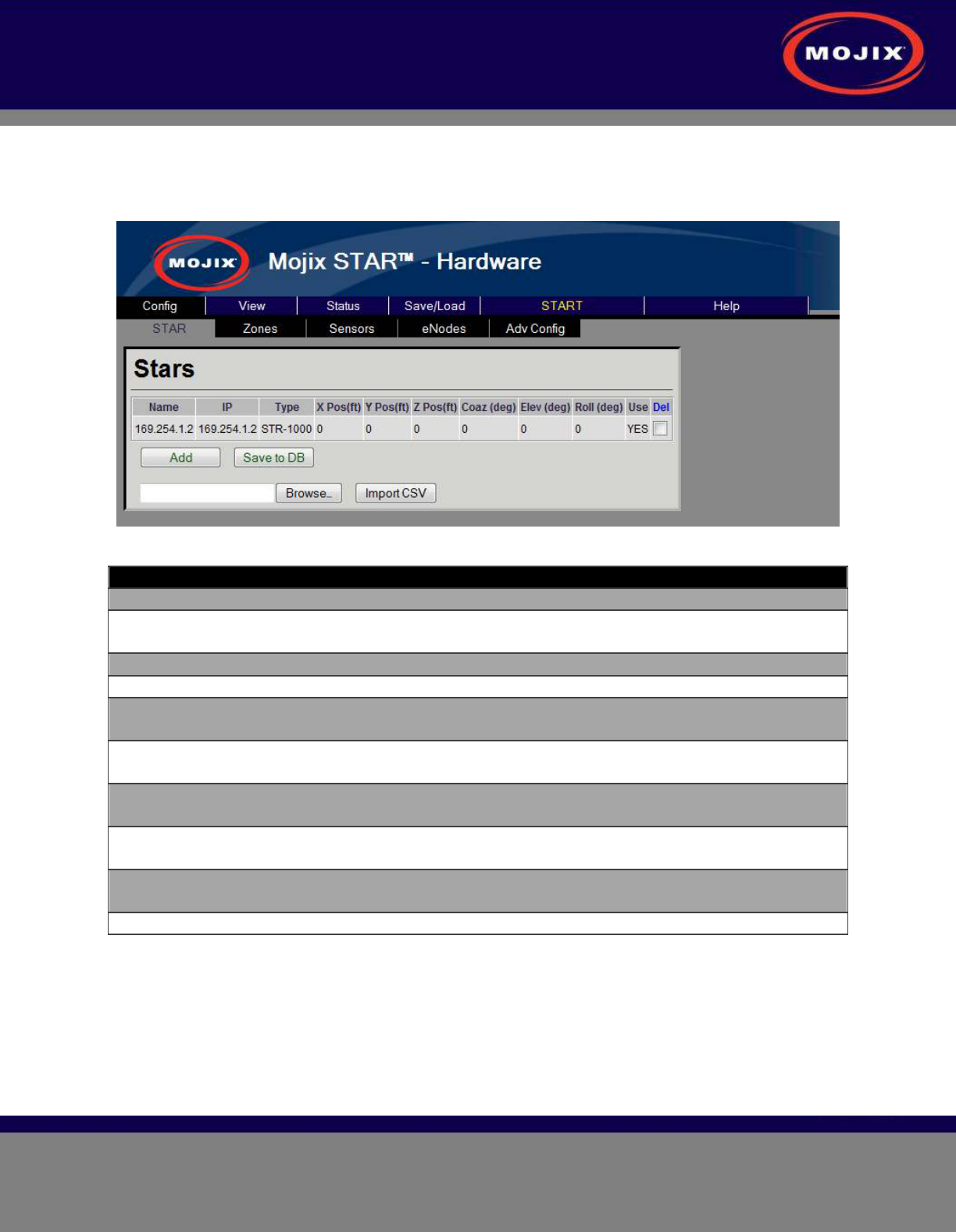
STAR Configuration
Figure 18: STAR Configuration page
Configuration Item Description
Name The name or IP of the STAR is entered in this field.
IP None editable. This displays the resolved IP address of the
entry in the Name field.
X Pos The X relative position of the STAR
Y Pos The Y relative position of the STAR
Z Pos The Z relative position of the STAR. In most conventions
this is the height of the STAR relative to the ground.
Coaz The coazimuth angle of the STAR receiver (angle rotation
relative to the X axis)
Elev The elevation angle of the STAR receiver (angle rotation
relative to the Y axis)
Roll The roll angle of the STAR receiver (angle rotation relative
to the Z axis)
Use If selected this indicates to the Mojix system that this STAR
is available for operation.
Del If selected this row will be deleted on “Save”
Table 4: STAR Configuration
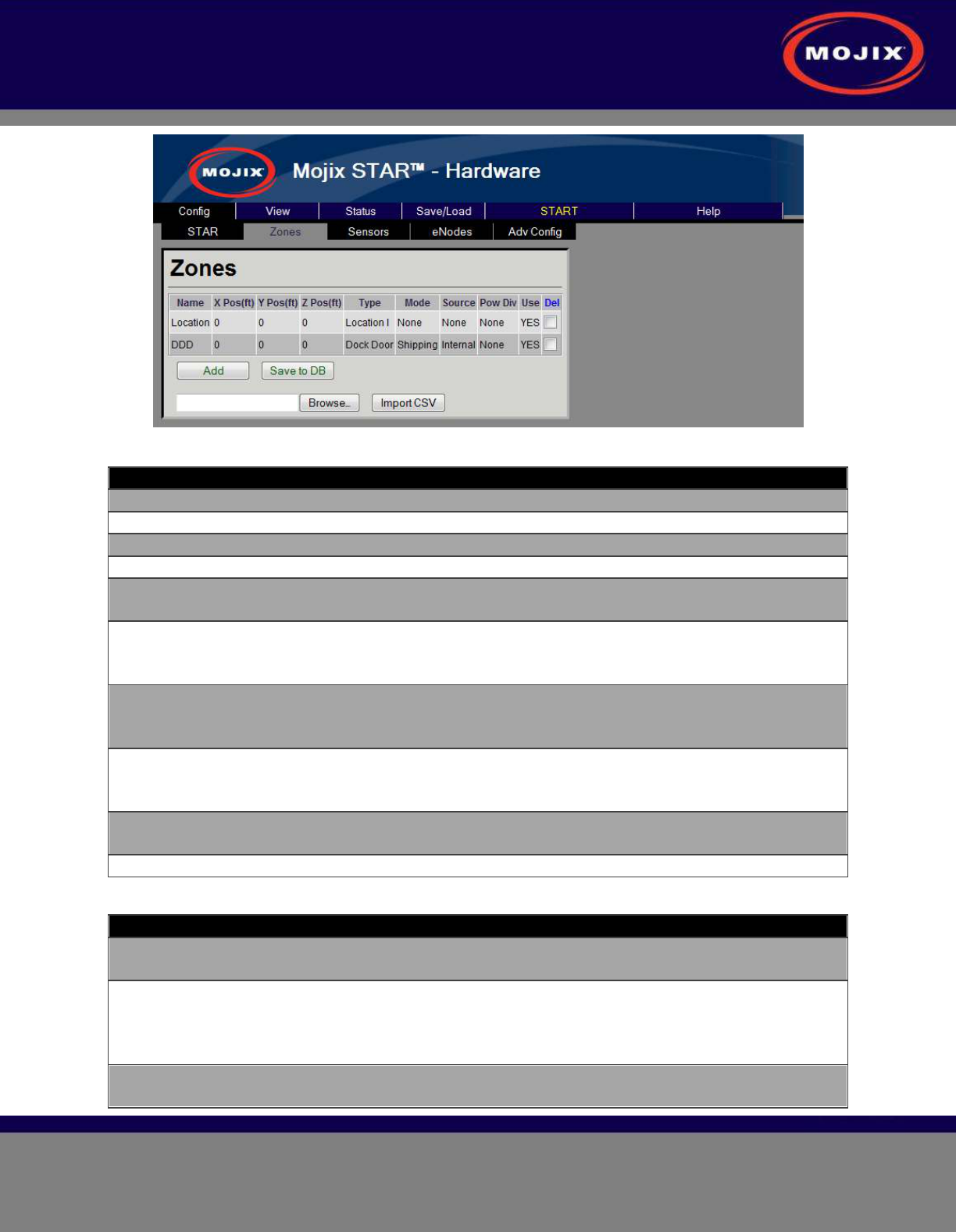
Zone Configuration
The Zone configuration page is used to configure areas of interest as either Dock Doors or Location zone
types.
STAR 3000 Installation Manual
Mojix Incorporated
www.mojix.com
(877) 886-6549
Page
26
of
45
Confidential and Proprietary
Figure 19: Zone Configuration page
Configuration Item Description
Name The name of the Zone (unique name are required)
X Pos The X coordinate relative position of the zone
Y Pos The Y relative position of the zone
Z Pos The Z relative position of the zone.
Type Configures the operation of the Zone, please refer to Zone
Type Descriptions in Table 6
Mode Configures the mode of operation for the Zone (only
applicable in DDD Zone types). Refer to Zone Mode
Descriptions in Table 7 for mode descriptions.
Source Configures the source of the sensor events that may trigger
the activation of the zone. Refer to Zone Source
Descriptions in Table 8 for source descriptions.
Power Div Configures the zone to use a power diversity profile
specified by the label that is defined in the Power Diversity
Configuration page.
Use If selected this indicates to the Mojix system that this Zone
is available for operation.
Del If selected this row will be deleted on “Save”
Table 5: Zone Configuration
Configuration Item Description
DDD Identifies this zone as a Dock Door zone. Objects moving
through this zone will be processed by the DDD application
Location I Identifies this zone as a Location zone. Objects moving
through this zone will be processed by the Location
application. This zone will be but into the background if
any sensor is tripped.
Location II Same as "Location I" but the group does not go into the
background ever (always on).

STAR 3000 Installation Manual
Mojix Incorporated
www.mojix.com
(877) 886-6549
Page
27
of
45
Confidential and Proprietary
Table 6: Zone Type Descriptions
Configuration Item Description
Shipping This indicates to the system that all events that are
triggered by this zone will be leaving the coverage area.
Receiving This indicates to the system that all events that are
triggered by this zone are product that will be entering the
coverage area.
Bidirectional This indicates to the system that events that are triggered
by this zone are product that will be entering or leaving the
coverage area.
None Used for Location zones
Table 7: Zone Mode Descriptions
Configuration Item Description
Internal This indicates to the Mojix system that sensor events that
trigger zone activation will be from internal Mojix sensors.
External This indication to the Mojix system that sensor events that
trigger zone activation will be received externally from the
Mojix system through the ALE logical reader interface.
None Used for Location zones
Table 8: Zone Source Descriptions
Power Diversity Configuration
The Power Diversity configuration page is used to configure a power profile that can be selected on the
Zone configuration page. The power profiles are used in conjunction with the Location application to
provide greater accuracy.
Figure 20: Power Diversity Configuration page
Configuration Item Description
STAR 3000 Installation Manual
Mojix Incorporated
www.mojix.com
(877) 886-6549
Page
28
of
45
Confidential and Proprietary
Name The name of the Zone (unique name are required)
Start delta from default (dB) The power profile starts from the power defined in the
eNode page plus this delta. All levels are measured in dB.
Step Size (dB) This indicated how much the power will be adjusted for
each step size.
Num of Steps The configured the number of steps to perform.
Del If selected this row will be deleted on “Save”
Table 9: Power Diversity Configuration
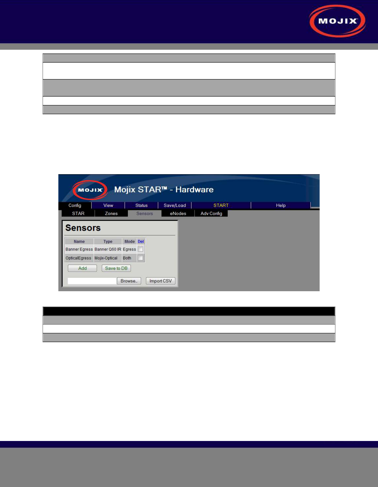
Sensor Configuration
The Sensor configuration page is used to configure sensors that will be used by the eNodes. Sensors
are physically attached to the eNodes and this configuration is done on the eNode page. The Mojix-
optical sensor is the only sensor that is not physically attached but still requires a virtual binding to an
eNode.
Figure 21: Sensor Configuration page
Configuration Item Description
Name The name of the Sensor (unique names are required)
Type Configures the type of Mojix supported sensors
Del If selected this row will be deleted on “Save”
Table 10: Sensor Configuration
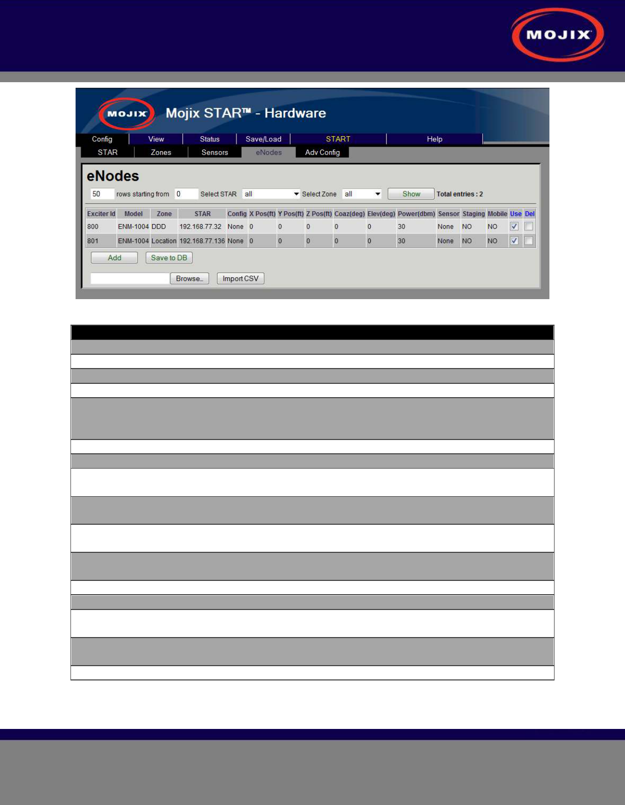
eNode Configuration
The eNode configuration page is used to configure every antenna on the Mojix system. Due to the
potential large size of deployment there is an easy sorting menu to assist in searching and finding the
necessary information. The interface supports filtering the information based upon the STAR and/or Zone
of interest. The Total entries indication is displayed showing the total number of antennas configured.
STAR 3000 Installation Manual
Mojix Incorporated
www.mojix.com
(877) 886-6549
Page
29
of
45
Confidential and Proprietary
Figure 22: eNode Configuration page
Configuration Item Description
Exciter Id The identification number of the transmitter
Model The model type of the eNode
Zone The Zone the exciter ID is associated to
STAR The STAR the exciter ID is connected to
Config A configuration template to aid in the configuration entry.
The antenna coordinates become editable only when
selecting None.
X Pos The X relative position of the antenna
Y Pos The Y relative position of the antenna
Z Pos The Z relative position of the antenna. In most conventions
this is the height of the antenna relative to the ground.
Coaz The coazimuth angle of the antenna (angle rotation relative
to the X axis)
Elev The elevation angle of the antenna (angle rotation relative
to the Y axis)
Power The roll angle of the antenna (angle rotation relative to the
Z axis)
Sensor The Sensor that is attached to the antenna
Staging Identifies the antenna as a “staging antenna”
Mobile Identifies the antenna as a mobile or roaming unit. This is
only applicable for the wireless eNode types.
Use If selected this indicates to the Mojix system that this STAR
is available for operation.
Del If selected this row will be deleted on “Save”
Table 11: eNode Configuration
Location Configuration
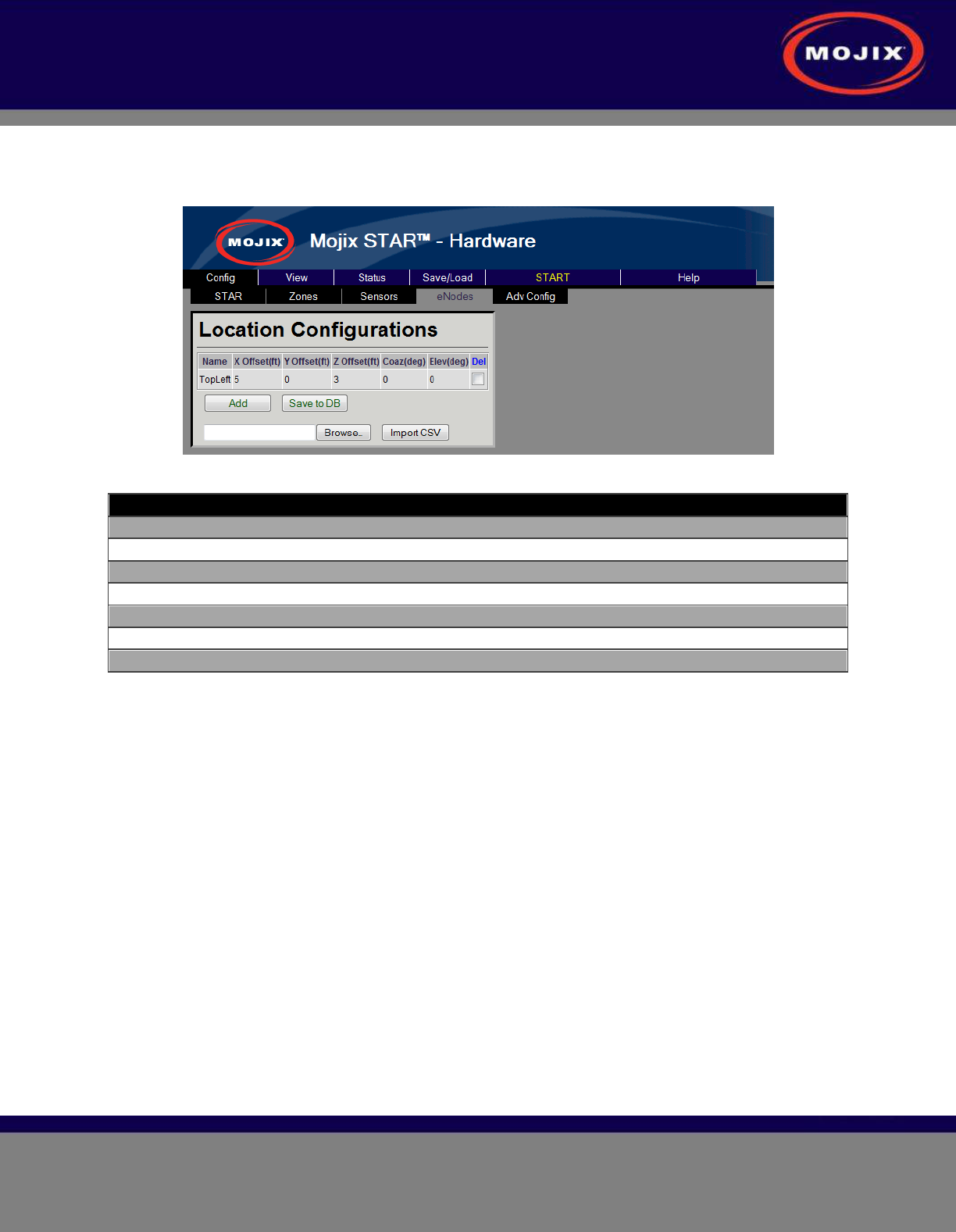
STAR 3000 Installation Manual
Mojix Incorporated
www.mojix.com
(877) 886-6549
Page
30
of
45
Confidential and Proprietary
The Location Configuration provides a mechanism to quickly configure the deployment by defining offsets
from the Zone location. When configuring an antenna the location will be the geometric sum of the Zone
center location and the defined location configuration.
Figure 23: Location Configuration page
Configuration Item Description
Name The name of the location template
X Offset The X offset position of the antenna
Y Offset The Y offset position of the antenna
Z Offset The Z offset position of the antenna
Coaz The coazimuth angle offset of the
Elev The elevation angle offset of the antenna
Del If selected this row will be deleted on “Save”
Table 12: Location Configuration
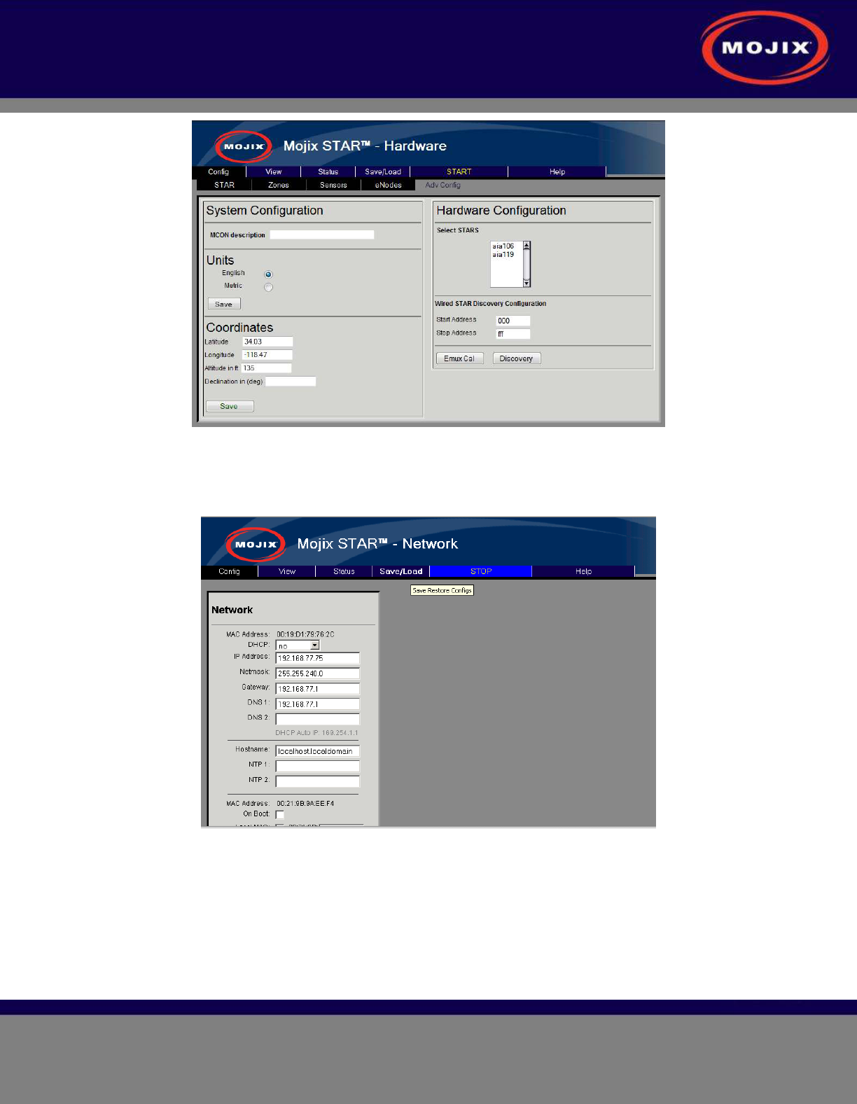
Advanced Configuration
The Advanced Configuration page allows the configuration of several advanced MCON features.
• System Configuration
• MCON Description: Provides ability to add a header to the banner. This additional text will
be displayed on every page
• Units : System units
• Coordinates : Absolute coordinates of the MCON
• Hardware Configuration
• Emux Cal: Performs an eMux calibration on the selected STARs.
• Discovery: Performs a discovery on the selected STARs in the address range specified
STAR 3000 Installation Manual
Mojix Incorporated
www.mojix.com
(877) 886-6549
Page
31
of
45
Confidential and Proprietary
Figure 24: Advanced Configuration page
Network Configuration
The Network selection opens the configuration screen for the MCON’s network settings.
Figure 25: Network Configuration page
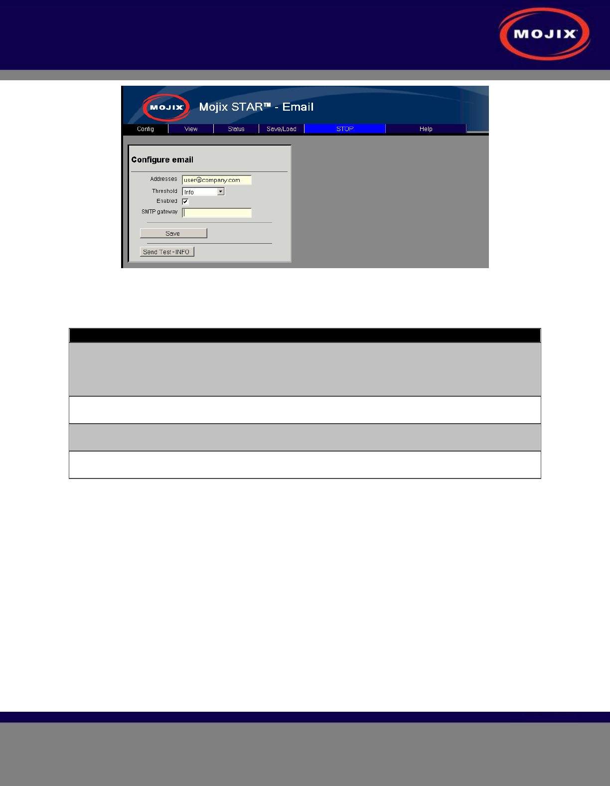
Email Configuration
The Email selection opens the configuration screen for the MCON’s email settings. Users can enter an
email address here where all MCON status report messages should be sent.
STAR 3000 Installation Manual
Mojix Incorporated
www.mojix.com
(877) 886-6549
Page
32
of
45
Confidential and Proprietary
Figure 26: Email Configuration page
Configuration Item Description
Addresses List of email addresses that will receive status messages.
The list can be separated by a space, comma, or semi-
colon.
Example : user1@company.com, user2@company.com
Threshold Sets the minimum email alert threshold that the system will
email.
Enabled Enable selection. When enabled the system is active and
sends mail to the configured addresses.
SMTP gateway Entry for the SMTP gateway. When not configured the
system will use the MCON as the gateway.
Table 13: Email Configuration
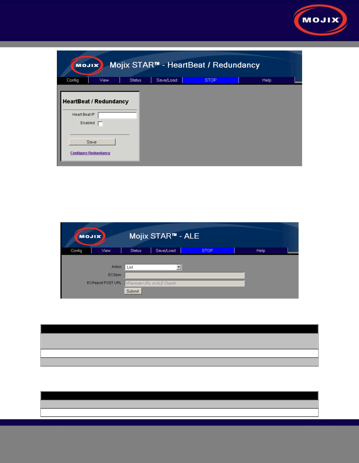
Redundancy Configuration
The Redundancy selection opens the configuration screen for the MCON’s ALE configuration.
Redundancy is the ability to detect that MCON elements are going to fail or have failed, and automatically
bring backup or redundant resources online. Refer to the Mojix Redundancy Configuration Application
Note for detailed information on configuration.
STAR 3000 Installation Manual
Mojix Incorporated
www.mojix.com
(877) 886-6549
Page
33
of
45
Confidential and Proprietary
Figure 27: Redundancy Configuration page
ALE Configuration
The ALE selection opens the configuration screen for the MCON’s ALE configuration. On this page you
can manage ECSpecs currently configured on the system.
Figure 28: ALE Configuration page
Configuration Item Description
Action Defines the specific operation that is desired. The support
operations defined below.
ECSpec Specifies the name of the ECSpec to create or modify
ECReport POST URL Specifies which URL the ALE reports will be sent to
Table 14: ALE Configuration
Action Description
List Lists available ECSpecs for subscription
Subscribe Subscribes <URL> to <ECSpec>
STAR 3000 Installation Manual
Mojix Incorporated
www.mojix.com
(877) 886-6549
Page
34
of
45
Confidential and Proprietary
Unsubscribe Unsubscribe <URL> to <ECSpec>
(Re)Define Door Spec Define <ECSpec> for configured zones with Dock Door
Type. If the zones are added or changed, a Redefine of
the <ECSpec> is required to pick up the new doors.
(Re)Define Loc Spec Define <ECSpec> for configured zones with Location Type.
If the zones are added or changed, a Redefine of the
<ECSpec> is required to pick up the new location zones.
(Re)Define HeartBeatSpec Defines a heartbeat <ECSPec>
Undefine Undefine <ECSpec>
Table 15: ALE Configuration Action Listing
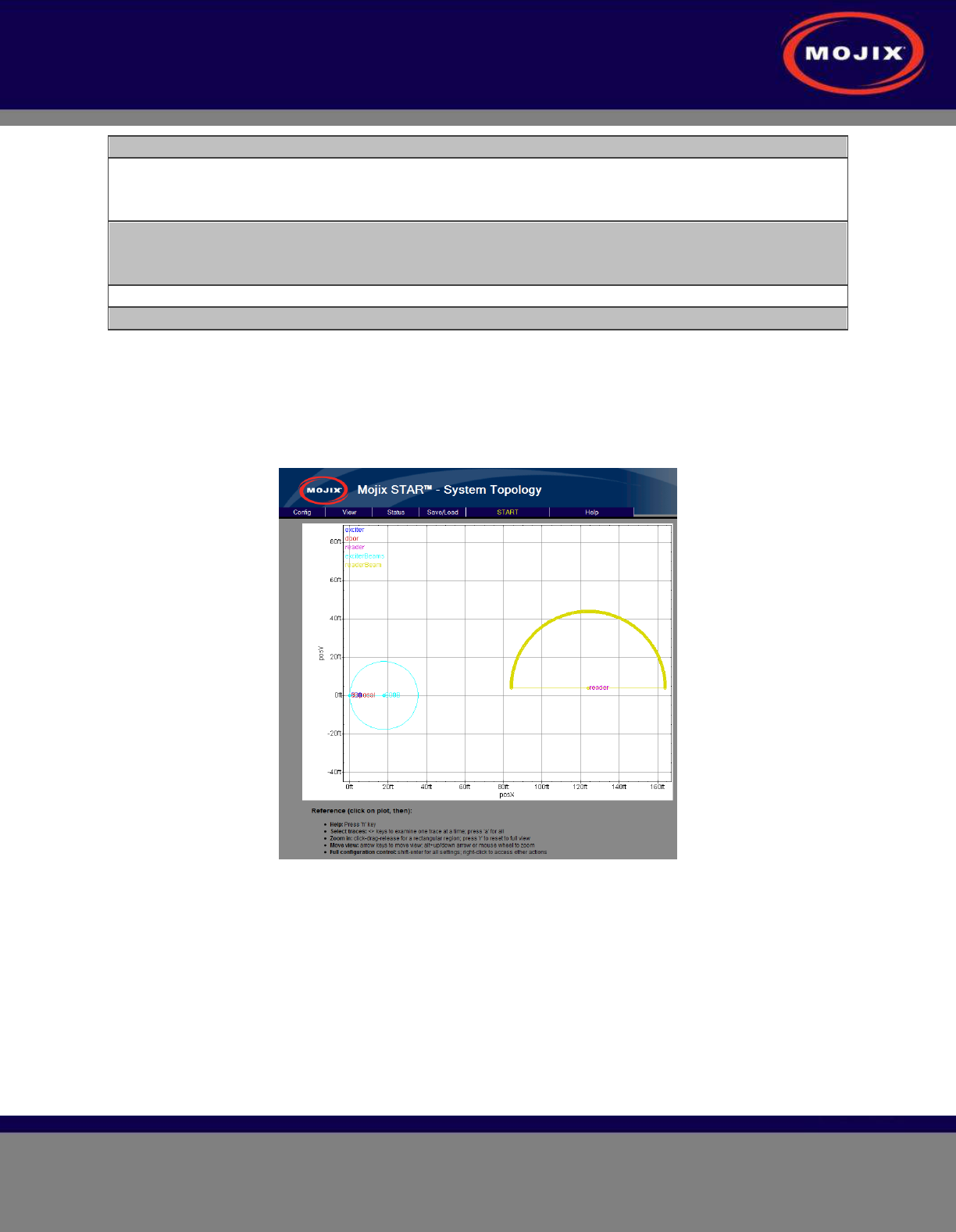
VIEW TAB
The Topology page is a 2-D graphical representation of the relative locations of the STAR and eNodes
configured so far. It is most useful as a check to see if the XY dimensions have been entered correctly.
The following figure shows the simple topology of a very basic setup.
Figure 29: View Topology Page
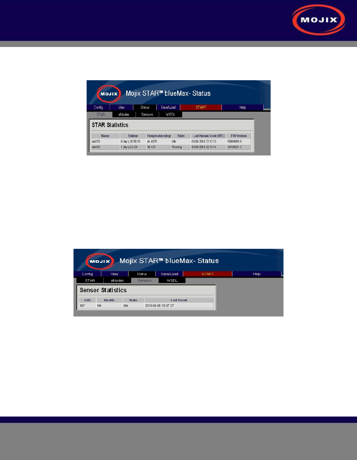
STATUS TAB
The Status tab provides an interface used to view hardware diagnostics. Pressing the STAR Status
button brings up the screen below with the following columns:
• Columns:
• Name: aiaName of the STAR.
• Uptime : Time for which the star has been running.
• Temperature : temperature in degree C as measured by the temperature sensor inside the
STAR .
STAR 3000 Installation Manual
Mojix Incorporated
www.mojix.com
(877) 886-6549
Page
35
of
45
Confidential and Proprietary
• State : Running/Idle
• Last Known Good : Time stamp indicating the LKG configuration wrt UTC.
• Firmware Version : Current BSP Version on the STAR.
Figure 30: STAR Status
It is possible to now use the lower toolbar to also see status on eNodes, Sensors and WSDL. For
example, below screen shows status on Sensors, with the following columns:
• Columns:
• txID : eNode ID to which sensor is connected.
• Health : health of the sensor.
• State : whether idle or tripped .
• Last Event : Last event of the sensor.
• Sensor Stats refreshed every 3 seconds.
Figure 31: Sensor Status
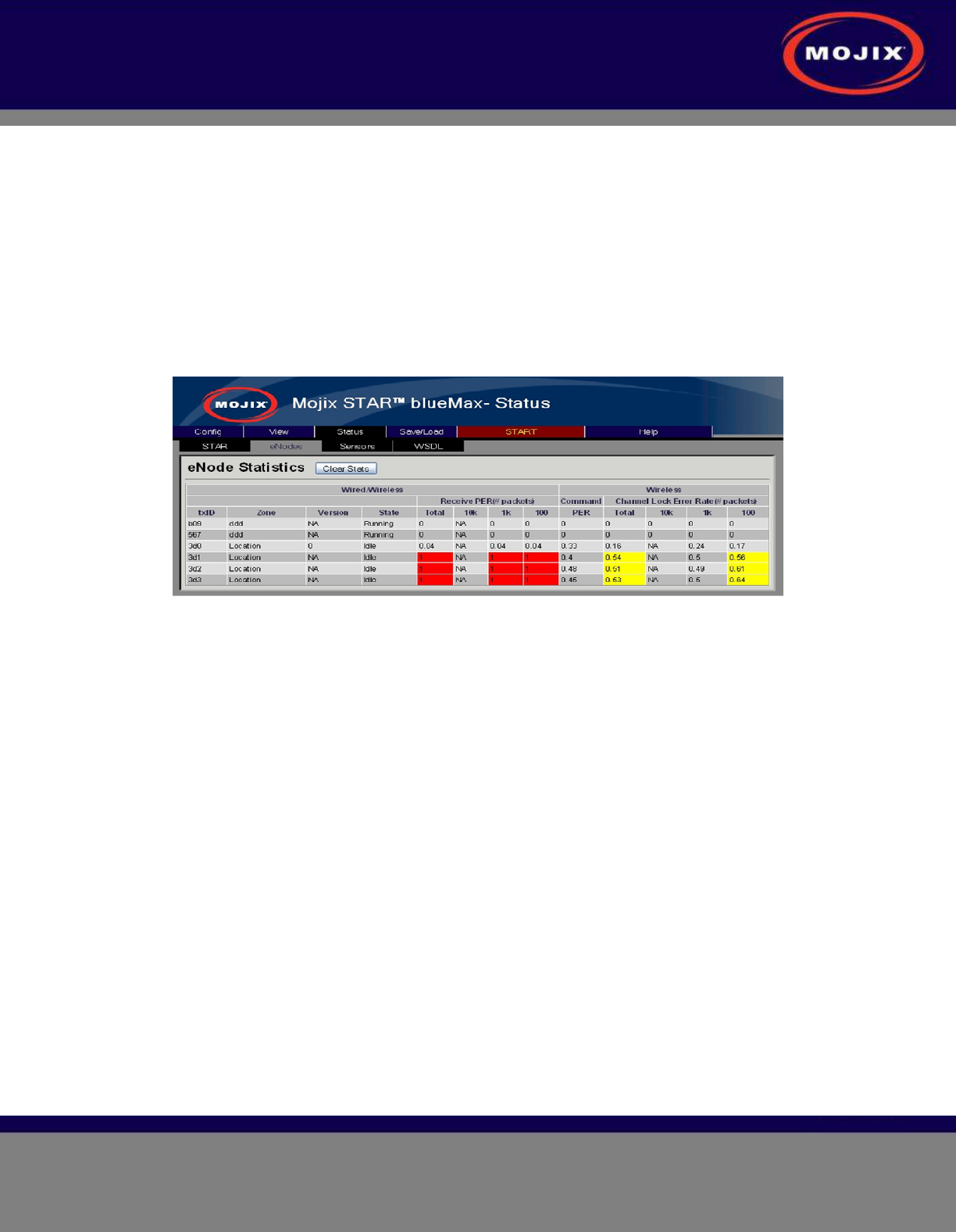
eNodes status is shown below, with the following columns:
eNodes Status
• PER are measured over different window lengths for both wireless and wired eNodes.
• Total : Overall packet error rate.
• 10K – packet error rate computed over the 10k most recent packets.
• 1k – PER over 1k most recent packets.
• 100 – PER over 100 most recent packets .
• Command PER and Channel Lock Error rate are applicable only for wireless eNodes.
STAR 3000 Installation Manual
Mojix Incorporated
www.mojix.com
(877) 886-6549
Page
36
of
45
Confidential and Proprietary
• Channel Lock Error rate is also measured over Total,10k,1k and 100 packets.
• Color coding used to indicate when error rates cross certain thresholds:
• Over 50% and less than 90% - yellow
• Over 90% -red
• Command PER is the PER for our fsk link .
• Channel Lock Error Rate is the error rate for our AFC loop.
• Clear Stats sends a trigger to database to reset it => deletes all database entries.
• Running / Idle state indicate whether the eNode is currently transmitting or not.
Figure 32: eNode Status
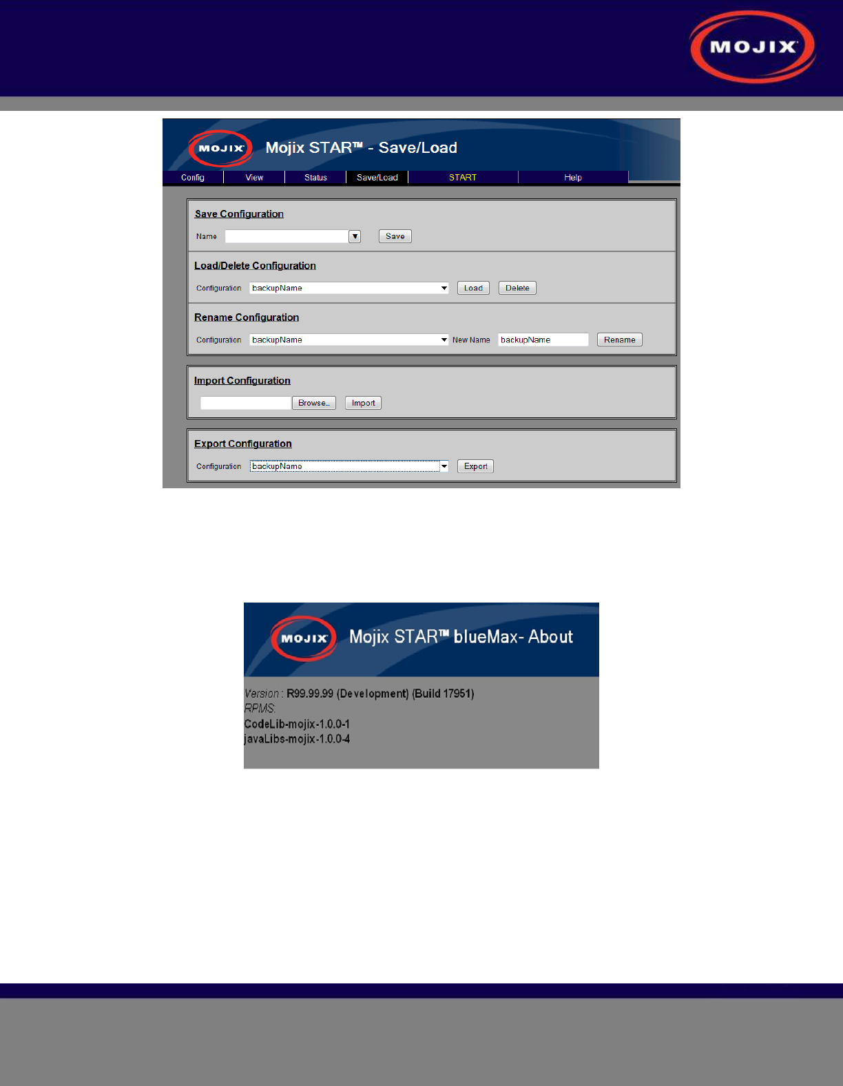
SAVE/LOAD TAB
The page allows the user to backup and restore save configurations.
• Save Configuration : Save the currently configured system
• Load/Delete Configuration : Loads the specified configuration overwriting the current settings
• Rename Configuration : Rename the selection to the New Name
• Import Configuration : Pushes a configuration saved on your local machine to the MCON. Note
: This action does not load the configuration. You will need to select the configuration and load it
for it to become active.
• Export Configuration : Takes a configuration off the MCON and allows the user to save the file
to their local computer.
STAR 3000 Installation Manual
Mojix Incorporated
www.mojix.com
(877) 886-6549
Page
37
of
45
Confidential and Proprietary
Figure 33: Save/Load Page
HELP TAB
About
This About shows the current version number of MCON software.
Figure 34: About Page
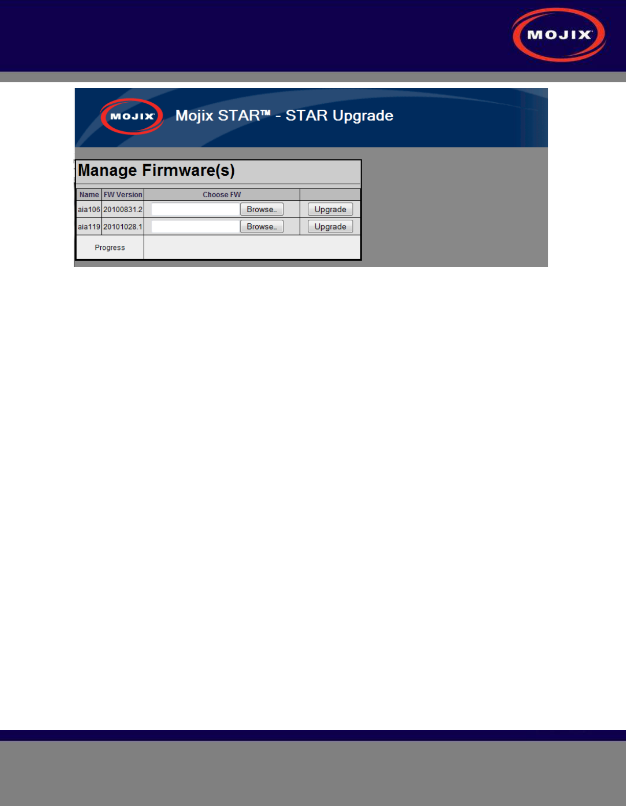
STAR Upgrade
This page provides the ability to upgrade the STAR with a firmware version supplied by Mojix.
STAR 3000 Installation Manual
Mojix Incorporated
www.mojix.com
(877) 886-6549
Page
38
of
45
Confidential and Proprietary
Figure 35: STAR Upgrade Page
STAR 3000 Installation Manual
Mojix Incorporated
www.mojix.com
(877) 886-6549
Page
39
of
45
Confidential and Proprietary
APPENDIX A: ENGINEERING INTERFACE - MOJO
Mojo provides users with an integrated interface for both configuration and execution of the system. The
functions of this interface are summarized as follows:
• STAR Parameter Configuration
• eNode Configuration
• Inventory Program Generation
• System Operation
To run Mojo, the user must connect to the MCON using VNC and bring up a terminal window by clicking
on the Terminal icon on the desktop. With the terminal window open, enter the following command to
launch Mojo:
$ Mojo<STAR ip>
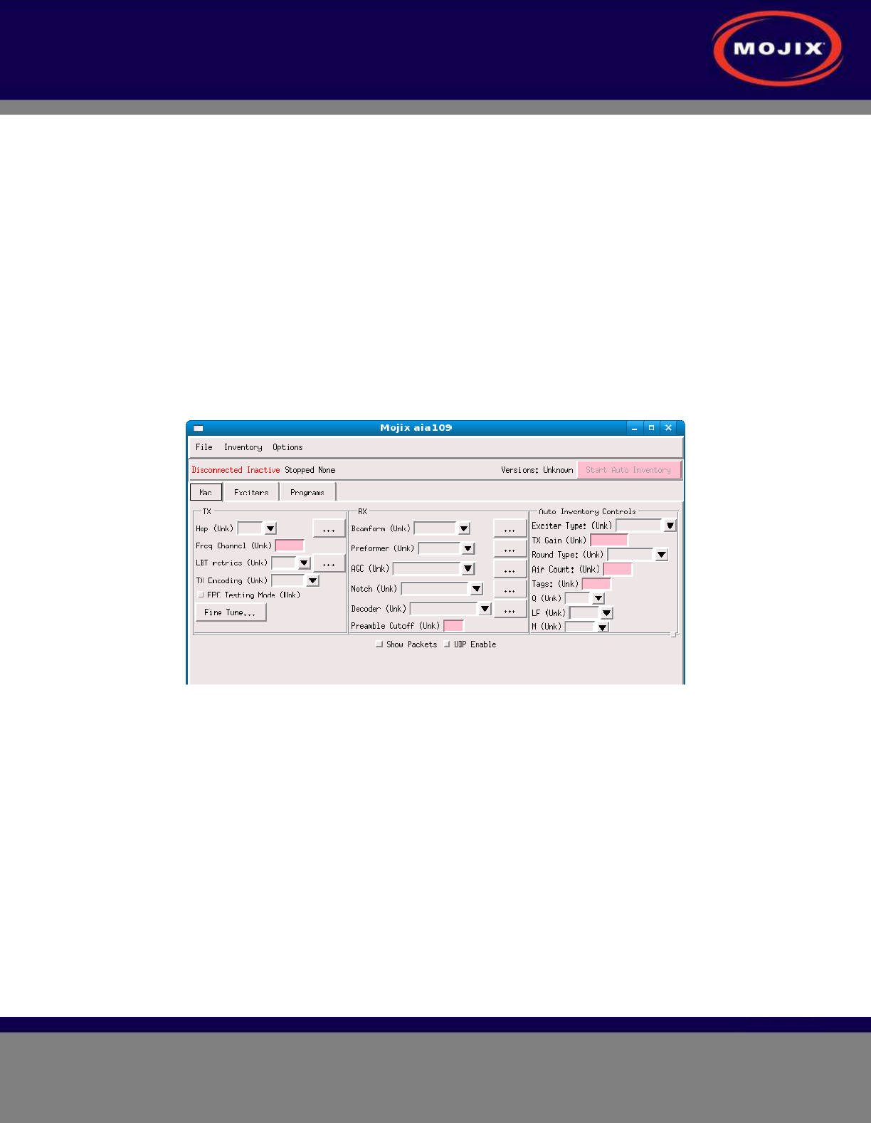
This will launch the Mojo application and the user will be presented with the following screen.
Figure 36: Mojo Main Screen
From here the user must click on the “File” menu and select “Connect”. This will establish a connection
between the MojoClient application and the STAR. At this point, the user can make real-time
configuration changes. The most basic configuration to begin reading tags would be to enter one or more
eNode addresses in the “Exciters” tab as shown in the following figure.
STAR 3000 Installation Manual
Mojix Incorporated
www.mojix.com
(877) 886-6549
Page
40
of
45
Confidential and Proprietary
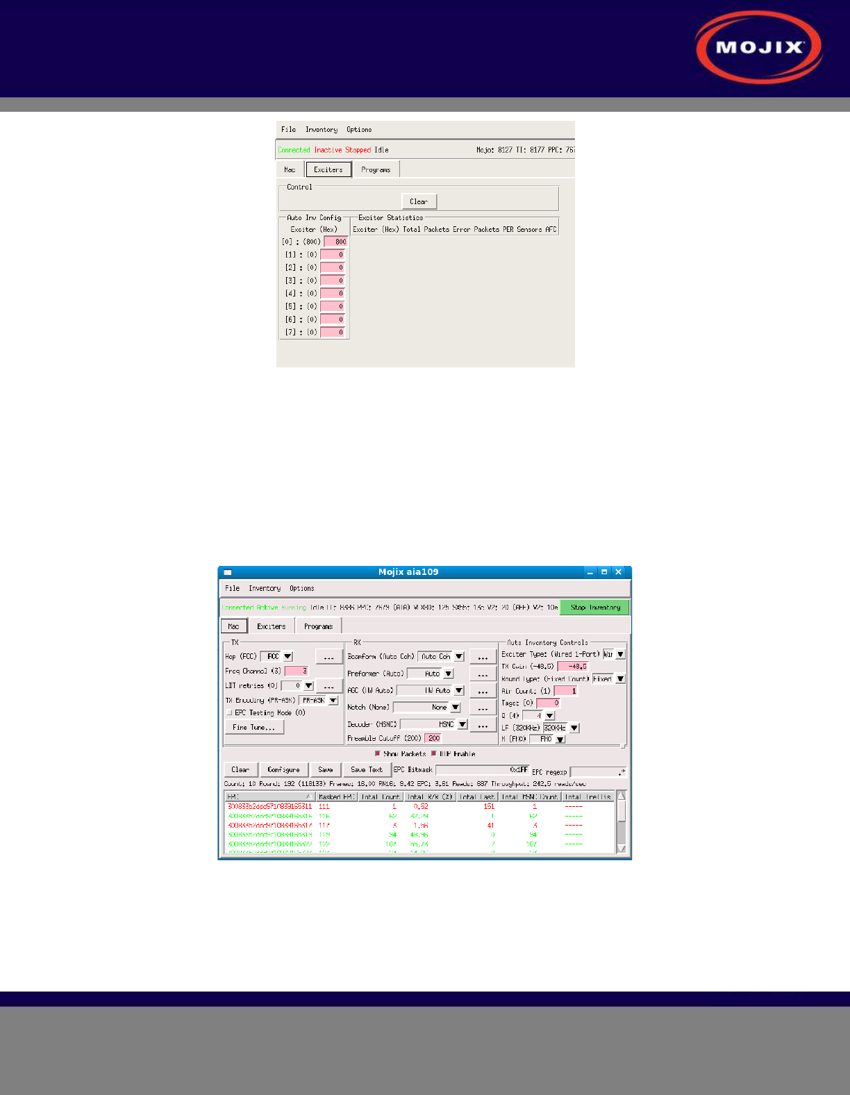
Figure 37: eNode Configuration (eNode Tab)
The address of an eNode is written on the eNode itself as the last three digits of the serial number. The
number is presented as three hexadecimal digits, for example, B89. The user must use the Enter key
when entering the eNode addresses in this window for the values to be accepted. Note, when the value is
accepted it will appear in parenthesis to the left of the text entry box.
Once the eNodes are entered, the user can return to the “Mac” tab and click on the “Start Auto Inventory”
Button in the top right corner. The Button will turn green when the system is running and the Button text
will change to “Stop Inventory”. This is how to start and stop tag reads. To view tag reads, the user must
select the “Show Packets” check box as shown in the following figure.
Figure 38: Tag Reads
Note that selecting the “Show Packets” box will redirect tag reads away from the MySQL database and to
the Mojo interface for display. Unselecting the box will return tag reads to the database. The EPC display
area at the bottom of the Mojo screen shows active tag reads.
STAR 3000 Installation Manual
Mojix Incorporated
www.mojix.com
(877) 886-6549
Page
41
of
45
Confidential and Proprietary
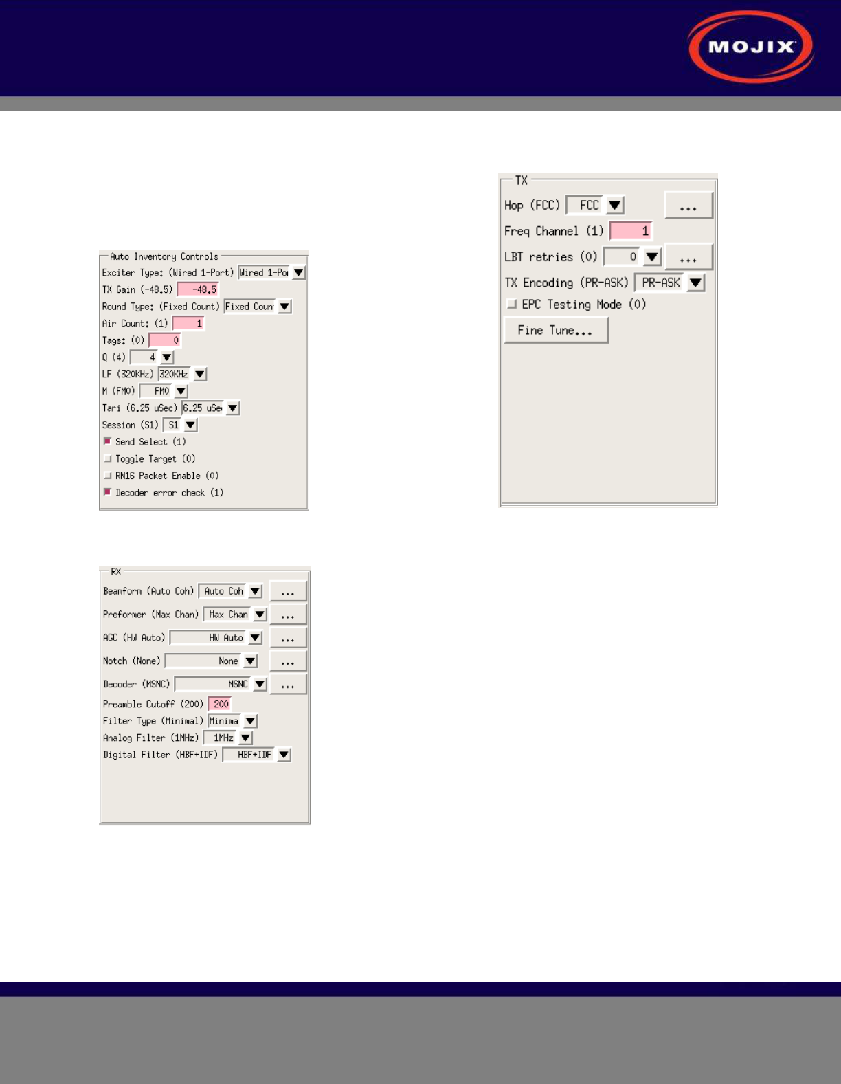
Figure 40: Auto Inventory Controls
Figure 41: Receive Parameters
Figure 39: Transmit Parameters
STAR 3000 Installation Manual
Mojix Incorporated
www.mojix.com
(877) 886-6549
Page
42
of
45
Confidential and Proprietary
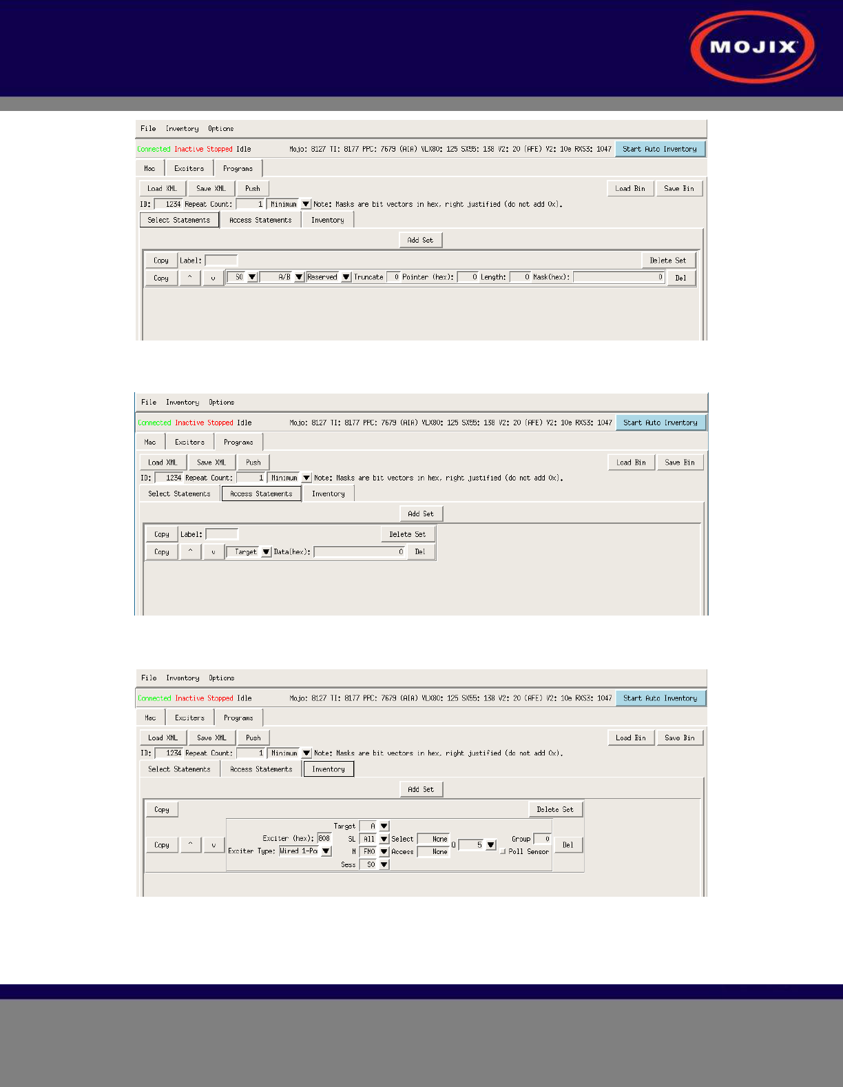
Figure 42: Select Statements
Figure 43: Access Statements
Figure 44: Inventory Programs

STAR 3000 Installation Manual
Mojix Incorporated
www.mojix.com
(877) 886-6549
Page
43
of
45
Confidential and Proprietary
APPENDIX B: FCC NOTICE, STAR 3000 AND ENODE
CAUTION: To comply with FCC RF exposure compliance requirements, a separation distance of
20 cm must be maintained between the antenna of this device and all persons.
WARNING: This equipment has been tested and found to comply with the limits for Class A digital device
pursuant to Part 15 of the FCC Rules. These limits are designed to provide reasonable protection against
harmful interference when the equipment is operated in a commercial environment. This equipment
generates, uses, and can radiate radio frequency energy and, if not installed and used in accordance with
the instruction's manual, may cause interference to radio communications. Operation of this equipment in
a residential area is likely to cause interference in which case the user will be required to correct the
interference at his own expense. However, there is no guarantee that interference will not occur in a
particular installation. If this equipment does cause harmful interference to radio or television reception,
which can be determined by turning the equipment off and on, the user is encouraged to try to correct the
interference by one or more of the following measures:
• Reorient or relocate the receiving antenna.
• Increase the separation between the equipment and receiver.
• Connect the equipment into an outlet on a circuit different from that to which the receiver is
connected.
• Consult the dealer or an experienced radio/TV technician for help.
In order to ensure compliance with FCC regulations, shielded and grounded cables must be used with
this equipment. Operation with non-approved equipment or unshielded cables is likely to result in
interference to radio and TV reception. The user is cautioned that changes and modifications made to the
equipment without the approval of manufacturer could void the user's authority to operate this equipment.

STAR 3000 Installation Manual
Mojix Incorporated
www.mojix.com
(877) 886-6549
Page
44
of
45
Confidential and Proprietary
APPENDIX C: FCC NOTICE, EMUX
WARNING: This equipment has been tested and found to comply with the limits for Class A
digital device pursuant to Part 15 of the FCC Rules. These limits are designed to provide
reasonable protection against harmful interference when the equipment is operated in a
commercial environment.
This equipment generates, uses, and can radiate radio frequency energy and, if not installed and
used in accordance with the instruction's manual, may cause interference to radio
communications. Operation of this equipment in a residential area is likely to cause interference
in which case the user will be required to correct the interference at his own expense. The user is
cautioned that changes and modifications made to the equipment without approval of the
manufacturer could void the user's authority to operate this equipment.

STAR System User Manual
Mojix Incorporated
www.mojix.com
(877) 886-6549
Page
45
of
45
Confidential and Proprietary
Mojix Incorporated
11075 Santa Monica Blvd., Suite 350
Los Angeles, CA 90025
Web: www.mojix.com
Tel: (877) 886-6549
E-mail: service@mojix.com
Need More Help? Our product support team is comprised of individuals highly experienced in RFID
deployments across a broad spectrum of application and use cases. If you are an existing customer of
Mojix, please login to the secure area and submit a service request if you have additional questions. If
you are unable to login, then please send us an email at: service@mojix.com.